Warnings
1、
2、
Please carefully read the manual of this product, connect
corresponding terminals strictly according to the power supply,
sensors and output/input of various parts indicated by the wiring
diagram, after inspection, re-tighten all bolts of the terminals, and
then energize them. Or, the wrong wiring may affect use and control,
in serious case, the temperature device or chip may be burnt out.
The product shall not be used in humid environment or in
occasions with corrosive gases and high-intensity magnetic fields, or
normal use of the product may be affected.
3、The product has been strictly inspected before factory,
warranty period of the product is one year, and our company is only
responsible for the sold product itself, not for any other joint
liabilities. If the damage is caused by the user's private disassembling
or improper use, our company will not provide warranty service.
Our company can produce series of all kinds of electric
temperature/humidity controllers, if you have any questions about our
products, please contact the dealers, our company will passionately
provide after-sales services for you, thanks!
Guangzhou Eliweli Autocontrol Tech. Co., Ltd.
http://www.eliweli.com
Wiring diagram
Parameters for Procedure
Failures
Reasons checked
Solutions
No display in connection state
Whether the power supply is disconnected;
whether there is failure in temperature control.
I n s p e c t t h e s u p p l y l i n e , a n d r e p l a c e t h e f u s e ;
Inspect whether end of the power supply has input or
contact the dealer for replacing the temperature control unit.
There is display, but the system
doesn't operate
Re-set the temperature control values needed;
inspect overload, and inspect reasons of overheating,
and then conduct trouble shooting.
Display that the temperature is
instable or there is malfunction
Route of the sensor is disturbed; the wiring is incorrect;
the route is bundled with other power supply line;
and the route may be damaged.
Separate the sensor from the power supply line,
or replace the shield line, and inspect whether
the wiring terminal is tightened.
The error between actual temperature and
the values measured with the controller is large
Installation position of various sensors are not correct;
The route is too long, therefore the resistance is large.
Contact on the route is bad; the sensor may be damaged.
Various se nsors must be corre ctly installed;
increase cross-section of the extension cord;
ensure sealing of the extension cord, waterproof and
moisture proof; and replace the sensors
The sensor is installed incorrectly; correct values can't be measured,
contact failures of the compressor.
Inspect whether the sensor can exactly measure
the temperature, replace contactor of the compressor.
The compressor works in over-frequency
The returning-difference temperature value is too low,
or the pressure protection setting is not correct.
Re-adj u s t an d incr e a se the return i n g- d i ffere n c e
temperature, and adjust setting of the pressure protector.
LL appears
Note: When the temperature sensor of storage-room is in failure,
the system enters failure operation mode.
Super-low-temperature warning or route of
the sensor is disconnected or short-circuited
Ins pect the data s et or ins pect whether the
connection between the sensor and feeder is correct.
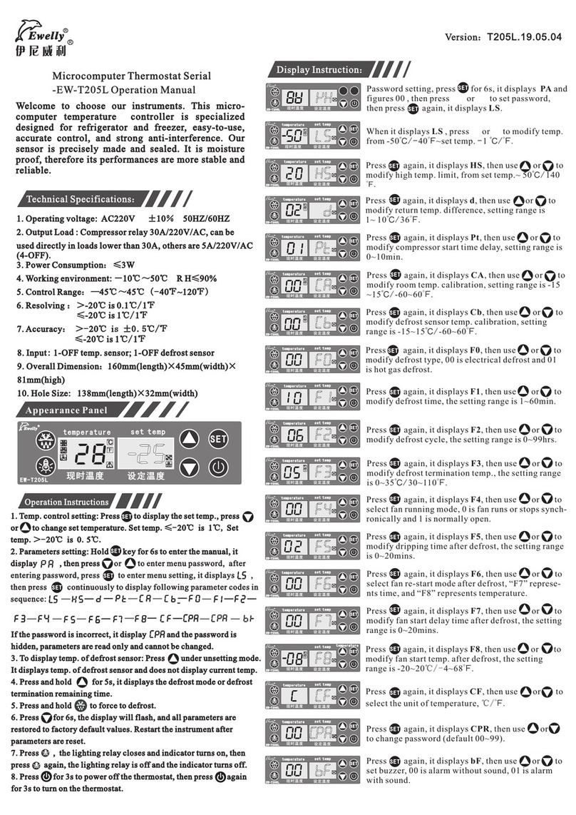
Operation mode of the fan after
defrosting (instructions )
Del a yed star t ing time
of the fan after defrosting
S t a r t i n g t e m p e r a t u r e
of the fan after defrosting
Minutes
℃
-
00=Operation of the parameter
v a l u e s b y p r e s s i n g F 7
01=Operation of the parameter
values by pressing F8
00~20 02
-20~20
-08
00
Instructions: If a password is set: The locking indication light is on, only correct CPA
is input ,other parameter values can be changed , or the set parameter values can only be viewed,
not modified, at the same time, the password menu is concealed, but the control temperatures
still can be changed.
When the password setting is 00, which means to cancel the password, at this time, the password
needs not to be input (the locking indication light is off).
When F6 is set as “00”, F7 is available, F8 is invalid; when the setting is “01”, F8 is available,
F7 is invalid;
Notes: The super-temperature treatment mode is as follows:
No warning during defrosting;
When the storage room's temperature (E2 is set as+10℃ ) is exceeded, HH warning is
output, the system enters failure operation mode, the compressor operates for 45min, and
ceases for 15 min;
When the storage room's temperature (the set temperature is -5℃ ) , LL warning is output,
at this time, all operations are stopped.
● ;
●
●
。
●Refrigeration: When current temperature≥ set temperature+ returning difference temperature, and the delay is set, when the “delay time” passes, the load relay acts.
The refrigeration stops: When current temperature≤ set temperature, the load relay is disconnected.
Function instructions
●
。
●
Entering defrosting mode: 1. When the instruments are defrosted (or started), the running period setting is operated, and then the system enters defrosting mode (relay of the fan
is disconnected, the indication light and relay act (the defrosting acts according to the sequence (note 2)).
2. Press the enforcing defrosting button for 6s, the system enters defrosting mode (note 1) (relay of the fan is disconnected, relay acts (the action sequence, see note 2).
Quit defrosting mode: 1. When the system enters defrosting mode, the set defrosting time is delayed, at this time, the defrosting light is off, the relay is disconnected (the action
sequence quitting defrosting mode, see note3), the system quits defrosting state and returns to normal control state.
2. When the defrosting sensor is up to quit temperature of defrosting, the defrosting indication light is off, and the relay is disconnected (the action sequence is as note 3),the
system quits defrosting state and returns to normal control state.
Code Function Setting range Factory setting Unit
Low-temperature setting
limit (notes)
High-temperature setting
limit (notes)
Delayed time
Temperature
correction
Returning difference
of temperature
-10.0~10.0
1~10
-49.9℃
20.0℃
00
1
2.0
℃
Minutes
Defrosting correction
Defrosting time
00
00~60 10
Defrosting period 00~99 Hours
06
Ending temperature
for defrosting
00~40
05
Starting mode of
the fan
0 0 = A l w a y s o p e r a t i o n
01=Synchronized operation
01
Input of the password 00~99 00
-15~15
-
Minutes
℃
℃
℃
℃
From -50.0℃ to the control
temperature of -1.0
Control temperature: +1.0
~ 50.0
Defrosting types 0
00=Defrosting with electric heating
01=Defrosting with hot gas
-
Water-dropping time
after defrosting
00~10 02 Minutes
-
0.1-15.0
℃
Note 1: When the “enforcing defrosting” button is pressed, if temperature of the defrosting sensor is ≥ ending temperature of defrosting, the system can't enter defrosting state, and
it will maintain current operation state.
Note 2: Action sequence of hot-gas defrosting relay: When the defrosting conditions are met, all relays are disconnected, the defrosting indication light is on, one minute later, the defrosting relay is closed; 30s
later, the compressor relay is closed.
Note 3: Action sequence of hot-gas defrosting relay in quitting defrosting: When the quitting conditions of defrosting is met, the defrosting light is off, relay of the compressor is disconnected, one minute later,
the defrosting relay is disconnected.
Setting of the
password
00-99
00
Treatment of common failures
Mode:EW-T207Z
34 5 6 7 8
12
Defrost
Storage
Temperature
NTC
sensor
220V/AC
30A
5A
9
Fan
Load
Defrost
5A
220V/AC
Machine does not stop when the temperature
reaches.
The temperature set is higher than current temperature;
Thermal protection inside the compressor is disconnected.
overload thermal protection is disconnected
because overrunning of the pressure;
