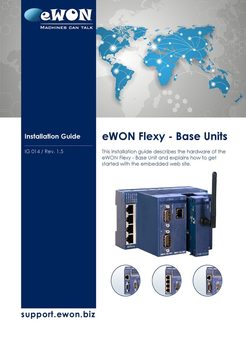
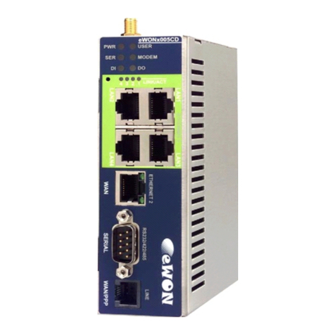
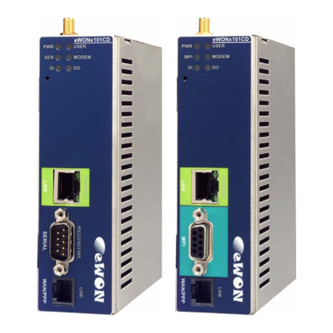
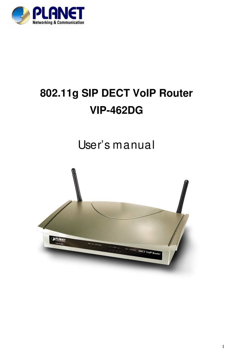
eWON 2005CD User manual

support.ewon.biz
eWON 2005CD
This installation guide describes the hardware of the
eWON 2005CD and explains how to get started with
it.
Installation Guide
IG 001 / Rev. 1.9

Table of Contents
1. Product description ............................................................................................................. 4
1.1. ntroduction ................................................................................................................................ 4
1.2. General specification of the hardware platform .......................................................................... 4
1.3. Functions of the eWON2005CD™ ............................................................................................. 5
1.3.1. General ............................................................................................................................ 5
1.3.2. Virtual Private Network .................................................................................................... 5
1.3.3. Remote Access Server functions ..................................................................................... 5
1.3.4. Ethernet to Serial Gateways ........................................................................................... 5
1.3.5. Programmable ndustrial Router functions ....................................................................... 5
1.4. Typical applications ................................................................................................................... 6
1.5. Part Numbers and internal options ............................................................................................ 6
2. eWON technical documentation ......................................................................................... 7
. Housing & markings ............................................................................................................ 8
3.1. Housing interfaces ..................................................................................................................... 8
3.2. Markings .................................................................................................................................... 9
3.3. Safety, Environmental & Regulatory nformation ..................................................................... 10
3.3.1. Scope ............................................................................................................................ 10
3.3.2. Applicable European Directives ..................................................................................... 10
3.3.3. Applicable Safety Standards .......................................................................................... 10
Battery .................................................................................................................................... 10
3.3.4. FCC Compliance ........................................................................................................... 10
3.3.5. Certifications .................................................................................................................. 11
3.4. Equipment information & versions ........................................................................................... 11
3.5. Mechanical Outline .................................................................................................................. 12
3.6. Mounting & environmental conditions ...................................................................................... 13
3.7. Preparing the installation ......................................................................................................... 13
3.8. Specification for external Power Supply selection ................................................................... 14
3.8.1. Auto-fuse ....................................................................................................................... 14
4. Front panel control LED's ................................................................................................. 15
5. Specifications of communication & I/Os Interfaces ....................................................... 16
5.1. Ethernet Ports ......................................................................................................................... 16
5.2. Embedded PSTN Modem (optional) ........................................................................................ 16
5.3. Embedded SDN Modem (optional) ......................................................................................... 16
5.4. Embedded GPRS-EDGE Quad-band Modem (optional) ......................................................... 17
5.5. Embedded GPRS-EDGE Quad-band Modem (optional) ......................................................... 17
5.6. Embedded UMTS Modem (optional) ....................................................................................... 18
5.7. Embedded HSUPA Tri-band Modem (optional) ........................................................................ 18
5.8. Embedded HSUPA Penta-band Modem EW2620B [Since S/N 1537-0108-xx included](optional)
18
5.9. S M-Card installation ............................................................................................................... 19
5.10. Configurable serial port ......................................................................................................... 20
5.11. MP port ................................................................................................................................. 21
5.12. Digital input ............................................................................................................................ 21
5.13. Digital output ......................................................................................................................... 22
6. IP parameters configuration ............................................................................................ 2
6.1. Resets ..................................................................................................................................... 24
Page 2 / 36 eWON 2005CD | G 001

Chapter 1
Endnotes
6.1.1. User Reset ..................................................................................................................... 24
6.1.2. Factory Reset ................................................................................................................ 24
Appendix A - Pin-outs & connections .................................................................................. 26
A.1 - Power Supply ......................................................................................................................... 26
A.2 - Ethernet ................................................................................................................................. 26
A.2.1 - Ethernet LAN ............................................................................................................... 26
A.2.2 - Ethernet WAN .............................................................................................................. 27
A.3 - Direct connection ................................................................................................................... 28
A.4 - Connection over Hub/Switch/Router ...................................................................................... 29
A.5 - RJ-45 Connector .................................................................................................................... 29
A.6 - nputs/Outputs ....................................................................................................................... 30
A.7 - Serial Port .............................................................................................................................. 31
A.8 - MP Port ................................................................................................................................. 32
A.9 - PSTN/ SDN Phone line connector ......................................................................................... 33
A.10 - Antenna ................................................................................................................................ 34
A.11 - Antenna for HSUPA EW2620B [Since S/N 1537-0108-xx included] ..................................... 35
Revision ................................................................................................................................. 6
Revision History ............................................................................................................................ 36
Page 3 / 36 eWON 2005CD | G 001

Chapter 1
Product description
1. Product description
1.1. Introduction
The eWON2005CD™ is the Compact Design evo ution of the eWON2005™.
The eWON2005CD™ is the Industrial LAN/Modem Router version of a comp ete range of
Ethernet/Internet gateways a so known as “Programmab e Industria Routers” (PIR). See our
web site http://www.ewon.biz to get further information about the eWON range. The eWON
is a termina that enab es access to technica data, whatever their format is. It is
configurab e by web pages. It is secure because it meets the toughest industria standards
and has restricted access features (required in open networks).
The eWON2005CD™ can optiona y embed a modem (PSTN, ISDN, GPRS-EDGE or HSUPA).
The eWON range supports the TCP/IP and PPP protoco s. This brings you a the benefits of an
universa y recognized standard network. It a so a ows you to use popu ar software too s ike
Internet Exp orer, FTP c ient, SNMP Manager, Mai Recipient … and so to reduce significant y
your costs (imp ementation and ownership).
1.2. General specification of the hardware platform
• Processor ARM c ocked @ 75Mhz, 16Mb SDRAM, 32Mb F ash
• Backed up rea time c ock (RTC) with 24 Hours autonomy
• Battery with 10 years ife expectancy (for RTC)
• Externa 12-24 VDC +/- 20%, consumption: 10W max
• 1 Ethernet port 10/100Mb BaseTx
• 1 Ethernet switch with 4 ports 10/100Mb BaseTx
• 1 Seria port configurab e in RS232/RS422/RS485 OR 1 MPI port (up to 12 Mbits/sec)
• 1 digita input (DI)
• 1 digita output (DO)
• DIN rai mounting comp iant with EN50022 ( atch)
• Environmenta conditions (operating):
Ambient T°: from -20°C to +70°C for eWON with GPRS-EDGE or HSUPA modem
Ambient T°: from 0°C to +50°C for eWON with PSTN or ISDN modem
Humidity: from 0 to 80% non-condensing
Page 4 / 36 eWON 2005CD | G 001

Chapter 1
Product description
1. . Functions of the eWON2005CD™
1. .1. General
•Ethernet Gateway to seria protoco s
•Web server – fu y customizab e web pages
•Programmab e by BASIC scripts and Java
•A arm management
•Report generation
1. .2. Virtual Private Network
A ow to bui d your own Virtua Private Network (VPN) thanks to OpenVPN techno ogy
1. . . Remote Access Server functions
•Remote Access Server (RAS) and TCP/IP Server
•PAP/CHAP Authentication
•Login/password
•Remote network access
•User access contro
•Security: NAT, IP fi tering
•Conventiona and internet ca back
1. .4. Ethernet to Serial Gateways
•MODBUS TCP to MODBUS RTU
•XIP to UNITELWAY
•Ethernet/IP™ to DF1
•FINS TCP to FINS Host ink
•ISOTCP to PPI (optiona y MPI)
•VCOM / ASCII
1. .5. Programmable Industrial Router functions
•Automatic routing of protoco s
•Programmab e routing from I/O and Tag names (BASIC)
Page 5 / 36 eWON 2005CD | G 001

Chapter 1
Product description
1.4. Typical applications
•A arm management
•Sending a arms by network, phone, Emai and/or SMS
•Remote measurements, oop back, contro and monitoring
•Predictive and operationa maintenance
•Diagnosis and machinery status contro
•Process and machinery activity ogs
•Commissioning support
•Remote programming
•Interface for App ication Service Providers (ASP)
1.5. Part Numbers and internal options
Part Number structure of the eWON product range:
EWaabzm
aa = Type of hardware platform 26 = eWON2005CD™
b = Power Supply 2 = Low vo tage 12-24DC
z = Serial Port type 0 = RS232 / RS422 / RS485
6 = MPI
m= Modem 1 = No modem (Ethernet on y)
3 = ISDN EU modem
4 = PSTN 56k modem
7 = GPRS-EDGE Quad-band
A = HSUPA Tri-band modem
B = UMTS G oba modem [Before S/N 1537-0108- *Not included]
B = HSUPA Penta-band modem [Since S/N 1537-0108-
*included]
Type/Description Part Number
eWON2005CD™/Ethernet only (No modem) EW26201
eWON2005CD™/ISDN (ISDN modem) EW26203
eWON2005CD™/PSTN 56 (PSTN 56 modem) EW26204
eWON2005CD™/GPRS-EDGE (GPRS-EDGE modem) EW26207
eWON2005CD™/HSUPA (HSUPA Tri-band modem) EW2620A
eWON2005CD™/UMTS/HSUPA (HSUPA Penta-band modem) EW2620B
eWON2005CD™-MPI/PSTN 56 (PSTN 56 modem) EW26264
Examp es of Part Numbers for the eWON2005CD™ p atform.
Page 6 / 36 eWON 2005CD | G 001

Chapter 2
eWON technical documentation
2. eWON technical documentation
The eWON technica documentation is structured in 4 different eve s:
Level Title Contents
1Installation Guide
Hardware
(present document)
Detai ed description of the hardware p atform, of its interfaces, avai ab e
options.
Hardware specifications, conformity to standards.
Insta ation recommendations and pin-out of the connectors.
Exists for each eWON type
2Reference Guides
Software
Exhaustive reference guides to use a advanced functions of the eWON:
•Genera Reference Guide (RG-001)
•Programming Guide (RG-002)
•Web reference guide (RG-003)
3Application User Guides Guides covering one app ication topic. For examp es:
•eWON Getting Started
•eWON MPI-Te eservice
•Unite way topo ogy Gateway XIP
•...
4Knowledge Base Small document about one technical topic.
For examples:
•How to do a PING function with Basic
•eWON seria number structure
•eWON modem type
•...
A those manua s are avai ab e for down oad in PDF format on the eWON website:
http://support.ewon.biz.
Page 7 / 36 eWON 2005CD | G 001

Chapter
Housing & markings
.2. Markings
The identification abe of the eWON is p aced at the eft hand side of the housing. The abe
is composed of the fo owing fie ds:
The eWON Seria Number (SN) is an important traceabi ity too both for the user and for the
manufacturer. Therefore, next to the product abe , each eWON has its seria number stored
in the f ash memory. This SN is a so used in order to scan the network for eWONs and to
assign its IP address, subnet mask and gateway.
For more detai s, See Equipment information & versions.
Page 9 / 36 eWON 2005CD | G 001

Chapter
Housing & markings
. . Safety, Environmental & Regulatory Information
. .1. Scope
The present heading addresses Safety, Environmenta & Regu atory Information for the
eWON2005CD.
The eWON2005CD range inc uding its optiona modems be ongs to c ass A Information
Techno ogy Equipment (ITE). In a domestic environment this product may cause radio
interference in which case the user may be required to take appropriate measures.
. .2. Applicable European Directives
The eWON2005CD range is in conformity with the fo owing directives:
•EMC Directive 2014/30/EU
•RoHS Directive 2002/95/EsC
When app icab e*, the product conform to the corresponding artic es:
•RE directive 2014/53/EU
* App ies to eWONs with embedded wire ess modem.
. . . Applicable Safety Standards
The eWON2005CD range inc uding optiona modems is in conformity with the fo owing
safety standards:
•IEC/EN 60950-1
•UL 60950-1
•CSA-C22.2 No 60950-1-07
Battery
- CAUTION -
Risk of e plosion if battery is replaced by an incorrect type. Dispose of used battery according
to the instructions. Do not disassemble, crush or puncture battery. Do not attempt to open or
service battery. Do not dispose of batteries in a fire or with household waste.
. .4. FCC Compliance
The eWON2005CD range inc uding optiona modems comp ies with Part 15 of the FCC
Ru es. Operating is subject to the fo owing two conditions:
1. This device may not cause harmfu interference
2. This device must accept any interference received*
(*inc uding interference that may cause undesired operation)
Page 10 / 36 eWON 2005CD | G 001

Chapter
Housing & markings
The te ecommunication modu es used into the eWON routers meets regu atory
requirements.
They have been granted modu ar approva for mobi e app ications. Integrators may use
eWON with te ecommunication modu es in their host app ication that can be categorized
as mobi e devices without additiona FCC or R&TTE certification approva s if the fo owing
conditions are met (otherwise, additiona FCC approva s must be obtained):
•At east 20 cm (7.88”) separation distance between the antenna and the user’s body must be
maintained at a times.
•The eWON and its antenna must not be co ocated or operating in conjunction with any other
transmitter or antenna.
•To comp y with regu ations imiting both maximum RF output power and human exposure to
RF radiation, the maximum antenna gain, inc uding cab e oss, are given in the § 8.8.2
Antenna Specification
•No modifications can be made by the user that can be of inf uence on the EMC behavior of
the device.
. .5. Certifications
P ease check our http://support.ewon.biz page to get the current versions of:
•Dec aration of Conformity (DoC)
•Other officia documents inc uding certificates
.4. Equipment information & versions
The eWON hardware and software revisions can be checked with a web browser on the
eWON server.
Once ogged onto the eWON, c icking on the eWON ogo shows these revisions.
eWON info page detai s
Page 11 / 36 eWON 2005CD | G 001

Chapter
Housing & markings
.5. Mechanical Outline
The eWON must be fastened on a 35mm DIN rai comp iant with EN50022.
To put the unit in p ace, insert the upper s ider into the upper part of the rai , with the
eWON™ ti ed around 20°. Then push and rotate the eWON™ downward to put the unit
right.
The eWON2005CD™ is now safe y fastened.
(*) For HSUPA modem with part number EW2620A on y,
the SIM card drawer is ocated on eWON top side.
See Embedded HSUPA Modem
Page 12 / 36 eWON 2005CD | G 001

Chapter
Housing & markings
.6. Mounting & environmental conditions
The eWON unit has an IP31 protection grade.
It is therefore not suited for outdoor mounting.
The design of the unit is such that it has to be integrated in an enc osed e ectrica cabinet,
protected from excessive heat, humidity and dust. The eWON2005CD™ is comp ying to the
CE-marking requirements regarding e ectromagnetic compatibi ity (EMC) within an
industria environment.
The norma mounting position is wa mounted on Omega-type DIN-rai (EN 50022).
The unit is suited to work in any other position.
The equipment wi operate within specified to erances on y if the fo owing environmenta
conditions are respected:
Environment Conditions
Ambient temperature range -20°C to +70°C for eWON with GPRS-EDGE-HSUPA modem
0°C to +50°C for eWON with PSTN or ISDN modem
Ambient humidity 0-80% non-condensing
.7. Preparing the installation
The recommended free space in the cabinet for the eWON shou d be at east:
80-mm wide x 200-mm high x 160-mm deep (terminal block excluded).
A piece of rigid DIN-rai profi e (f at 35mm wide) of suitab e ength shou d be firm y fastened,
horizonta y, in the midd e of the area.
Grounding the eWON is necessary to e iminate unwanted transients ( ightning protection)
and to conform to the EMC requirements. Therefore, a ground screw is avai ab e at the top
of the unit. Connect this screw direct y to a ow impedance ground.
Page 13 / 36 eWON 2005CD | G 001

Chapter
Housing & markings
.8. Specification for external Power Supply selection
The eWON2005CD™ has to be supp ied by an externa vo tage source ranging from 12 to 24
VDC.
The power supp ied must be a C ass 2 or Leve 3, SELV-comp iant (Safety Extra Low Vo tage)
and imited in current to a max of 850mA.
The safety vo tage power supp y is not part of the de ivery.
The data given be ow is intended to a ow correct se ection of the externa power supp y:
Specification Value
Secondary PS voltage from 12 to 24 VDC +/-20% (SELV-comp iant)
Max secondary PS current 850 mA max.
eWON current protection 2A by auto fuse
eWON voltage protection 30V by transi
eWON EMI filter Common mode fi ter1
Power absorbed 10 Watts
Input Protection Protected against po arity inversion
Equipment Supp ied by C ass 2 or Leve 3 Power Supp y.
.8.1. Auto-fuse
An auto fuse p aced just after the power input protects the eWON devices against short
circuits. This component returns by itse f to its norma state when the short circuit has
disappeared and after the component has been coo ing down.
Wou d this fuse happen to operate, p ease check the device for presence of oose meta
parts inside ike y to generate a short circuit.
If the prob em recurs even after such a verification, then return the device to the vendor for
further investigation.
1Proper y ground the unit with the earth screw at the top of the unit. This is mandatory to
ensure the security and the e ectromagnetic compatibi ity (EMC) of the device.
Page 14 / 36 eWON 2005CD | G 001

Chapter 4
Front panel control LED's
4. Front panel control LED's
Front pane LED's description
Page 15 / 36 eWON 2005CD | G 001

Chapter 5
Specifications of communication & /Os nterfaces
5. Specifications of communication & I/Os Interfaces
5.1. Ethernet Ports
The eWON2005CDTM has 2 Ethernet interfaces:
•a LAN (Local Area Network) with an integrated 4 ports switch
•a WAN (Wide Area Network) with one port
Specification Value
Applicable standard 10/100BaseTX
Isolation 1,5 kV
Pin-out RJ45 connector See RJ45 connector
P ease refer to the appendix (Direct connection and Connection over Hub/Switch/Router) for
information on the different Ethernet connection modes (straight and crossed cab es).
5.2. Embedded PSTN Modem (optional)
Specification PSTN 56k
Max baud rate (V92) 56.000 bps
Pin-out phone line connector See PSTN/ISDN Phone Line
Leased Line mode No
5. . Embedded ISDN Modem (optional)
Specification PSTN 56k
ISDN specification ISDN BRI S0.I.430
Type 1B+D
Max baud rate 64 Kb
Certification - - -
Page 16 / 36 eWON 2005CD | G 001

Chapter 5
Specifications of communication & /Os nterfaces
5.4. Embedded GPRS-EDGE Quad-band Modem (optional)
Specification GPRS-EDGE
Bands Quad band EDGE 850/900/1800/1900 MHz
E-GPRS Class C ass 10
Max baud rate 115 kbps (theoretica )
Compliant to standards R&TTE, CE, FCC
Certificate number - - -
Antenna connector2Type SMA-F
5.5. Embedded GPRS-EDGE Quad-band Modem (optional)
Specification GPRS QB
Bands Quad band EGSM 850/900/1800/1900 MHz
Class GPRS C ass 10
Max baud rate 40 kbps (theoretica )
Compliant to standards R&TTE, CE, FCC
Certificate number - - -
Antenna connector3Type SMA-F
2 Tightening torque for SMA antenna connector: MAX 0.5N.m (manual tightening should be used as
a reference) See Antenna.
3 Tightening torque for SMA antenna connector: MAX 0.5N.m (manual tightening should be used as
a reference) See Antenna.
Page 17 / 36 eWON 2005CD | G 001

Chapter 5
Specifications of communication & /Os nterfaces
5.6. Embedded UMTS Modem (optional)
Specification UMTS Global
Bands Quad band EGSM (850/900/1800/1900 MHz)
Tri band UMTS/HSDPA (850/1900/2100 MHz)
Class GPRS Mu ti-s ot C ass 12
EDGE Mu ti-s ot c ass 12
Max baud rate 230 kbps (theoretica )
Compliant to standards R&TTE, CE, FCC
Certificate number - - -
Antenna connector (*) Type SMA-F
(*) Tightening torque for SMA antenna connector: MAX 0.5N.m (manual tightening should be used as
a reference) See Antenna.
5.7. Embedded HSUPA Tri-band Modem (optional)
Specification HSUPA
Bands Quad band EGSM (850/900/1800/1900 MHz)
Tri band UMTS/HSUPA (850/1900/2100 MHz)
Class GPRS Mu ti-s ot C ass 12
EDGE Mu ti-s ot c ass 12
Max baud rate 921 kbps (theoretica )
Compliant to standards R&TTE, CE, FCC
Certificate number - - -
Antenna connector (*) Type SMA-F
(*) Tightening torque for SMA antenna connector: MAX 0.5N.m (manual tightening should be used as
a reference) See Antenna.
5.8. Embedded HSUPA Penta-band Modem EW2620B [Since S/N 1537-0108-xx included](optional)
Specification HSUPA
Bands Quad band EGSM (850/900/1800/1900 MHz)
Penta band HSUPA (850/900/1700/1900/2100 MHz)
Class GPRS Mu ti-s ot C ass 33
EDGE Mu ti-s ot c ass 33
Max baud rate 921 kbps (theoretica )
Compliant to standards R&TTE, CE, FCC
Certificate number - - -
Antenna connector (*) Type SMA-F
(*) Tightening torque for SMA antenna connector: MAX 0.5N.m (manual tightening should be used as
a reference) See Antenna.
Page 18 / 36 eWON 2005CD | G 001

Chapter 5
Specifications of communication & /Os nterfaces
5.9. SIM-Card installation
Sim card insta ation is common to:
•GPRS-EDGE Modem
•GPRS quad band Modem
•UMTS Modem
•UMTS/HSUPA Modem with part number EW2620B
For HSUPA modem with part number EW26206B only,
the SIM-card drawer is ocated on the top of the eWON.
Page 19 / 36 eWON 2005CD | G 001

Chapter 5
Specifications of communication & /Os nterfaces
5.10. Configurable serial port
Specification Value
Physical modes (configurable) RS232/RS485/RS422
Isolation Not iso ated
Pin-out connector See Serial Port
The configuration of the physica seria mode is done by a set of 4 dip switches
ocated on eft side of the unit.
The settings of the switches
are shown in the tab e be ow
(note: switch 1 is the right one)
Position Mode
RS232
RS422, RS485
WITHOUT po arization and termination resistor
RS422, RS485
WITH po arization and termination resistor
- Note -
The 3 switch configurations shown here above are the sole configurations giving satisfactory results.
That switch 3 & 4 need to have the same position (both ON or both OFF). When they are ON, it
connects the internal polarization (typ 680 Ohms) and termination (typ 120 Ohms) resistors. This
configuration applies only to RS485/RS422 lines conforming to good practices.
- WARNING -
The switch 2 is reserved and must stay OFF.
Page 20 / 36 eWON 2005CD | G 001
Table of contents
Other eWON Network Router manuals

