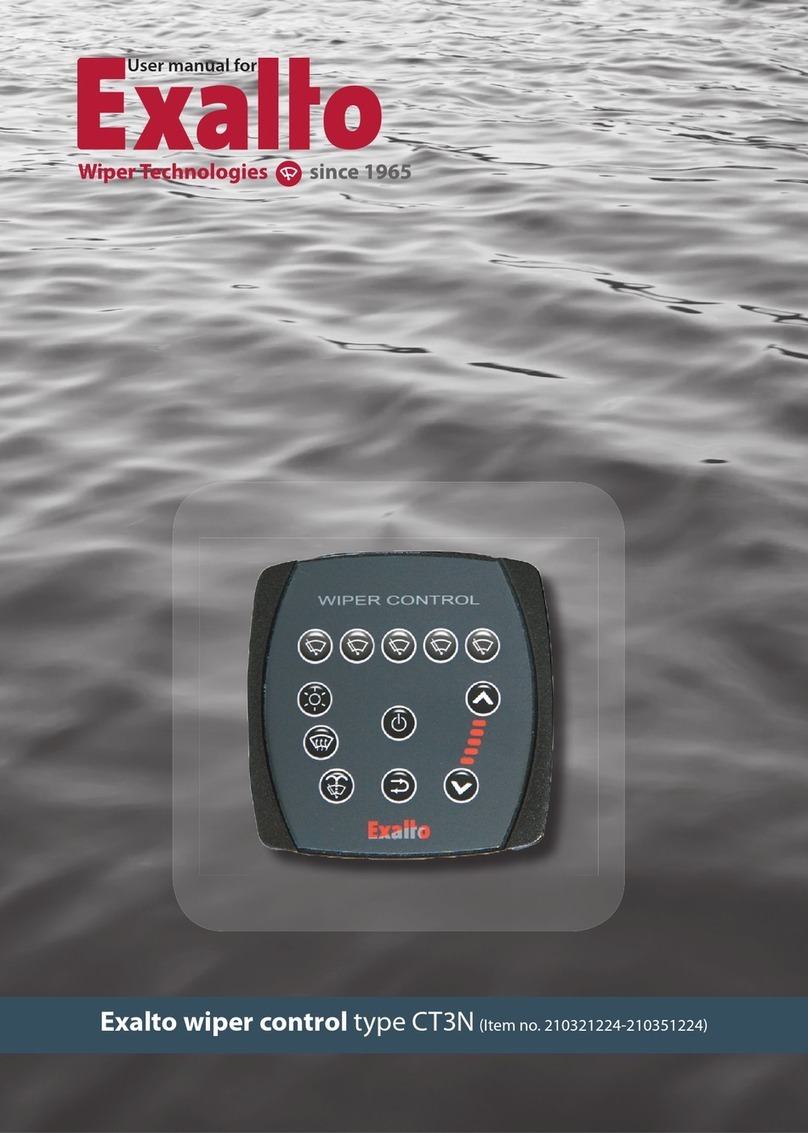
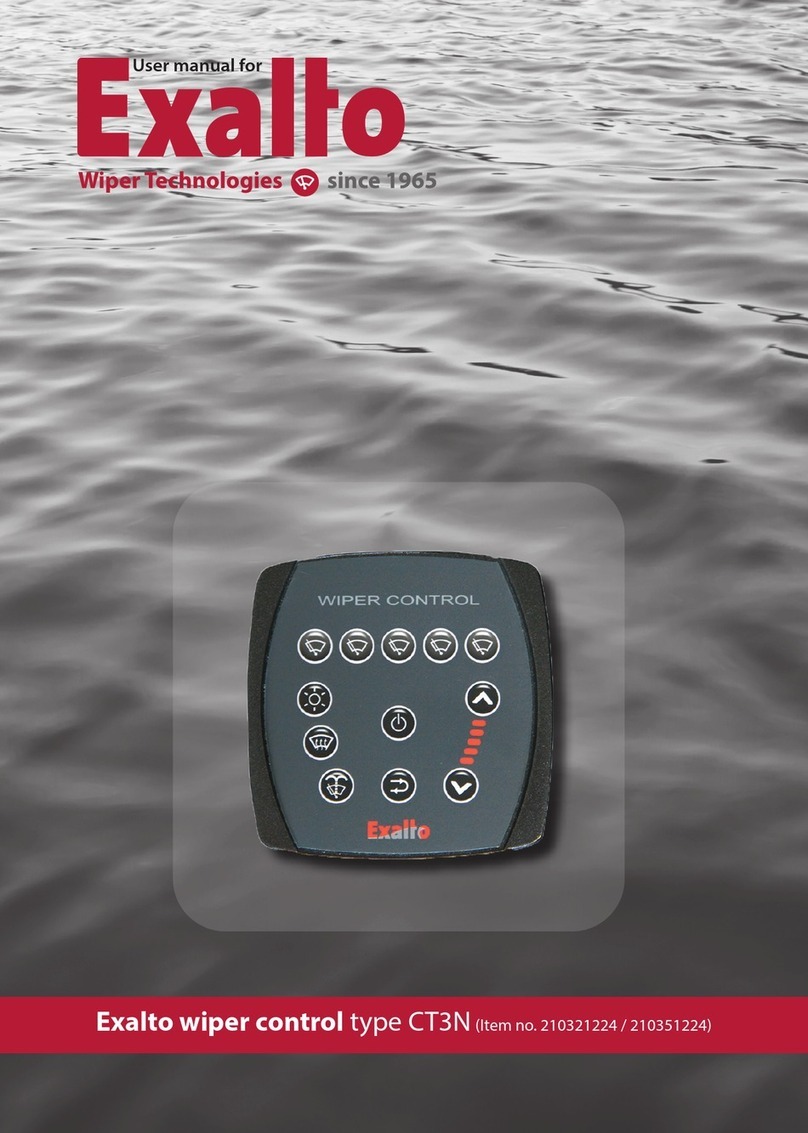
Exalto 214303 User manual

ITEM NO. 214303
WIPER SYSTEMS
Exalto wiper Controller
for three HD/MD wipers

MANUAL WIPER SYSTEMS
2
Contents
1. General
1.1 functions
1.2 general description
1.3 power supply
1.4 technical specifi cations
1.5 declaration of confi rmity
2. Installation
2.1 dimensions
2.2 installation
3. Electric connections
3.1 general lay out
3.2 wiring diagram
4. Operation
4.1 functions of the push buttons
4.2 on/o switching
4.3 increase speed - decrease speed - intermittent mode selection
4.4 signal mode
4.5 wipe/wash program
5. Failure
5.1 continuous fl ashing signal
5.2 reset function
6. Available models

MANUAL WIPER SYSTEMS
• 3
Exalto type 214303
1. General
1.1 Functions
Brief explanation of buttons and LED’s Please see section 4 for complete operating instructions.
Pos. Function
1 Main ON/OFF switch/wipe-wash program.
2 Increase speed
3 Decrease speed
4-6 Buttons allow activation and deactivation of each assigned wiper motor
1.2 General description
The 214303 is a micro-controller based intelligent switch for operating three Exalto HD/MD wiper
motors. It provides all the functions for a proper windscreen cleaning. It consists of a two control
switches with 45 cm (17”) connection cable and one control box.
This wiper control o ers:
• two continuous speeds
• three intermittent speeds
• activating / deactivating each wiper one by one;
• synchronosation in each selected mode;
• self parking due to dynamic brake
• individual wiper motor selection
Visual indications for ON, continuous and intermittent modes.
14
25
36

MANUAL WIPER SYSTEMS
4
1.3 Power supply
This wiper control is available to operate under a power supply of 12 or 24V DC. Check the power
supply of the unit supplied, before connecting it to the ship’s electric system.
1.4 Technical specifications
Model 214303
Wiper motor HD/MD motor series
Voltage 10V to 30V DC
Internal fuse 12 Amps PTC for each motor
Stand-by current less than 20 mA
Protection polarity inversion
Motor - output current single or double speed - 12 Amps max for each motor.
Input 3 parking switch (open in park position)
dimmer (see relay box connections paragraph)
Output
3 low speed - LOW
3 high speed - HIGH
1 wash pump (positive pole)
Functions
3 intermittent speed setting
2 continuous speeds (low and high speed)
wash/wipe program
switches leds brightness regulation (if present)
Connections
relay box primary switch
3 four poles connector
2 male 9,5 mm fast-on
1 eight poles tel. connector
1 four poles minifit connector
1 eight poles tel. connection
1 ten poles tel. connector
secondary switch
1 ten poles tel. connection
Case Grey ABS Black ABS
Working temperature -25 °C / +55 °C
Storage temperature -30 °C / +80 °C

MANUAL WIPER SYSTEMS
• 5
Exalto type 214303
1.5 Declaration of conformity
This wiper control is in conformity at requisition of electromagnetic compatibility and of security with
directives, 2014/30/EU 9EMC) and 2011/65/EC (RoHS)
Harmonize norms apply:
• CEI EN 60945 ed 2003 + IEC 2018-04: MARITIME NAVIGATION EQUIPMENT AND SYSTEMS
• EN 50581 ed 2012: RoHS
Supplementary information:
• The European directive 2014/35/EU (Low Voltage) is not applicable to this product as this device
is powered by voltage values below 50Vac or 75Vdc.
• The cabling systems that will be installed on the product, should be conform their own safety
requirements. The system complied with the requirements of IMO A.813 Decision about protec-
tion against interference on maritime radio communications.

MANUAL WIPER SYSTEMS
6
2. Installation
2.1 Dimensions
All dimensions in mm. Dimensions relaybox in mm.

MANUAL WIPER SYSTEMS
• 7
Exalto type 214303
2.2 Installation
The touch pad is to be fi tted at a location that is within suitable reach to allow for ease of operation.
Make sure that su cient room is available for the cables and the connectors. The required mounting
hole for the touch pad is 36.5 x 21 mm (2 times). There should be at least 100 mm space available
under the front of the touch pad for the connection cable and plug.
Important
Protect the power supply line(s) by a thermal/magnetic circuit breaker. Thermal/magnetic circuit
breaker and cables diameter must be sized according to the motor consumption and the regula-
tions. Please make sure you insert the connector (linked to the wiper motor) before connecting the
power supply!

MANUAL WIPER SYSTEMS
8
3. Electric connections
3.1 General switch plug lay out
3.2 Wiring diagram
Colour coding for wiper motor.
Function Polarity Motorcode Switch code Cable
High speed + 53b H White
Low speed + 53 L Yellow
Negative - 31 Black
Stop - self park 31b P Blue
Positive + 53a B Red
Park
Slow
Fast
– M
(Recommended)
M
5A
Wash
+
–
–
W
ash
Fast
Slow
Park
– M
+ –
Power
Supply

MANUAL WIPER SYSTEMS
• 9
Exalto type 214303
Colour code and connection of wiring coming from the 214303 controller:
• Green is to be connected to the Positive (53a) of the motor wire.
• Blue is to be connected to the Negative (31) and Stop/Self Park
(31b) of the motor wire.
• Yellow is to be connected to the Low Speed (53) of the motor
wire.
• White is to be connected to the High Speed (53b) of the motor
wire.
• Brown is to be connected to a pump or solenoid.
Always refer to the User Manual as supplied with the Exalto Wiper
before connecting the Exalto wiper to the wiper switch.
Connections to relay box.

MANUAL WIPER SYSTEMS
10
4. Operation
4.1 Functions of the push buons
All push buttons have a double function as described in the chart (see paragraph 4.4).
4.2 ON/OFF switching
By pressing and releasing button 1 or 2, the wiper can be switched ON or OFF. By pressing button 1 a
fast blinking LED will indicate the new wiper selection as in following chart:
Mode LED ( = on) Signal
Both wipers ON Fast blinking
Right wiper only Fast blinking
Left wiper only Fast blinking
Both wipers OFF LED’s OFF
4.3 Increase speed - decrease speed - intermient mode selection
The wiper motor starts in SLOW speed mode (the only possible continous mode if one speed-motor
is used). By pressing button 2, the motor will power to FAST SPEED.
By pressing button 3, you can step down through the speed modes:
- SLOW SPEED - 2 SEC. INTERMITTENT - 4 SEC. INTERMITTENT - 8 SEC. INTERMITTENT.
By pressing button 2 you can step up through the speed modes.
4.4 Signals mode
The three LED’s shows the controller operation setting. By pressing any button, the mode will
change. The LEDS will fl ash as many times as the delay times (in seconds) between the wiper
strokes (if 4 seconds is the delay times between the wiper strokes, the LED will fl ash 4 times) or the
LED’s will have a light fl ash (slowly when SLOW speed is selected and quickly when FAST speed is
selected).
Mode LED ( = on) Signal
FAST speed Fast slight blink
SLOW speed Slow slight blink
2 sec. delay 2 slow blink
4 sec. delay 4 slow blink
8 sec. delay 8 slow blink
OFF LED’s OFF
Wipe/wash
Failure Asymm. Continuous flashing signal

MANUAL WIPER SYSTEMS
• 11
Exalto type 214303
4.5 Wipe/wash program
This wiper control has a built-in ‘smart’ wipe/wash program. The program is as shown below. By
keeping button 1 pressed for more than one second, the Wipe/wash program will be activated. After
the Wipe/wash program has ended, the wiper will return to the wipe setting that was previously
used.
5. Failure
5.1 Continuous flashing signal
A continuous fl ashing signal indicates that the 210342 does not receive one or both parking switch
signals or it is not possible to reach synchronism. This may occur if:
• one or both parking switches are damaged or disconnected;
• one or two wiper motors do not run (damaged or disconnected);
• one or two wiper motors do not run in fast or slow speed;
• wiper motors run at too much di erent speeds and it is not possible to reach synchronism;
• 10-pin connector has been inserted after power supply and control works as with one speed
motor.
5.2 Reset function
With any failure it is important you fi rst perform a reset process to the control system:
• turn power o to the wiper controller
• remove the 10-pin connector from the back of the console
• inspect that all terminals are located correctly and in position
• make sure the motor is connected correctly to the console
• wait 30 seconds
• reconnect the 10-pin connector to the back of the console
• turn power on
• test operation of the wiper controller
• if problems continues, check notes on section 5.1
6. Available models
• 214303 Wiper controller for 3 wiper, max 12mA;
3 seconds 4 seconds 3 seconds
Spray Spray
Wipe Wipe

MANUAL WIPER SYSTEMS
12
exaltowipers.com
Exalto Wiper Technologies
Nijverheidsstraat 12
3371 XE Hardinxveld-Giessendam
The Netherlands
+31 (0)184 615 800
wipers@exalto.com
exaltowipers.com
Exalto WiperTechnologies
Nijverheidsstraat 12
3371 XEHardinxveld-Giessendam
The Netherlands
+31 (0)184 615 800
wipers@exalto.com
Version 01-2022
Table of contents
Other Exalto Controllers manuals