Exalto CT3N User manual

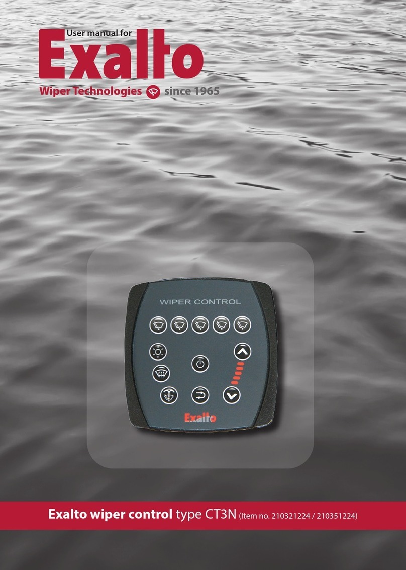
Exalto wiper control type CT3N (Item no. 210321224-210351224)
User manual for

- Exalto Wiper Technologies type CT3N
2

Exalto Wiper Technologies type CT3N - 3
Contents
1. General
1.1 Features
1.2 Standard supply
1.3 System configuration
2. Buttons functions and signalings
3. Operating mode
4. Wash program
5. Single wipe function
6. Heating function (optional)
7. Backlight brightness and colors
8. Power supply
9. Failures and signallings
9.1 Reset function
9.2 Motor fault
9.3 Communication error
10. Installation
11. System wiring
12. Ordering information
13. Technical information
Declaration of conformity

- Exalto Wiper Technologies type CT3N
4
1. General
CT3N is an electronic wiper control system for up to five motors. CT3Nn is composed
by one control panel and one relay box. The control panel and the relay box are con-
nected by an CAT5 cable (CAN Bus cable).
1.1 Features
• Double voltage supply: 12V - 24V
• Activates/deactivates each wiper one by one
• Synchronization in every mode
• Three (four with one speed motors) intermittent settings
• Dynamic brake
• Wipe/wash program
• Single wipe function
• Heater activation (additional relay box required)
• Selection of backlighting color and brightness
• Fault and error signaling
1.2 Standard supply
• 1 x Control panel
• 1 x Relay box
• 1 x 5 meter cable or CAN Bus connection
• 1 x 4-poles female connector for Relay box to motors connection
(1 for each motor)
• 1 x female 6,3mm fast-on terminal for washing pump connection
• 2 x (or 4 if more than 3 wipers) female 9,5mm fast-on terminal for power supply
connection
1.3 System conguration
Model No. of wipers Control panel Relay box Art. code
CT3N2 2 210321224.P 210321224.R 210321224
CT3N3 3 210331224.P 210331224.R 210331224
CT3N4 4 210341224.P 210341224.R 210341224
CT3N5 5 210351224.P 210351224.R 210351224
If user need two stations, wire up the adding panel (optional) via CAN BUS to the
relay box.

Exalto Wiper Technologies type CT3N - 5
2. Buttons functions and signallings
1. Single wiper ON/OFF button
2. General ON/OFF button
3. Backlighting color and brightness button
4. Heaters button (additional relay box required)
5. Wash button
6. Single wipe button
7. Decrease speed / increase intermittent delay
8. Increase speed / decrease intermittent delay
9. Selected mode led bar
3. Operating mode
The operating mode available depends on the number of the motor’s speeds.
If using two-speed motors:
Speed bar Waiting time Mode
All Leds OFF - Stand-by
1 x Led ON 8 seconds Intermittent
2 x Led ON 4 seconds Intermittent
3 x Led ON 2 seconds Intermittent
4 x Led ON - Continuous (slow)
5 x Led ON - Continuous (fast)
1
2
3
4
5
6
8
7
9

- Exalto Wiper Technologies type CT3N
6
If using one speed motors:
Speed bar Waiting time Mode
All Leds OFF - Stand-by
1 x Led ON 8 seconds Intermittent
2 x Led ON 6 seconds Intermittent
3 x Led ON 4 seconds Intermittent
4 x Led ON 2 seconds Intermittent
5 x Led ON - Continuous
4. Wash program
By pressing the wash button, washing program will start.
|3 sec. | 3 sec. | 4 sec. |
|=== Spray === Spray ===|
|===== Wipe ===== Wipe ===|
Keep pressed button 5 to increase wash timing and spray + wipe time. After wash
cycle, wipers will return to operate in the previous selected mode.
5. Single wipe function
The single wipe function is allowed only when all the wipers are off. Push the button
6 to perform the single wipe. Keep pushed to perform more than one wipe.
6. Heating function (additional relay box required)
The control panel can activate/deactivate the heaters, only if a relay box (additional)
is installed. The button 4 actives the heaters when pushed. To deactivate push the
button again. When the heaters are active, the button is lighted up.
7. Backlight brightness and colors
The button 3 performs the brightness adjustment and the color selection. Pushing
it momentary the brightness level will change. Four brightness levels are available.
Keeping it pushed the backlighting color will change.

Exalto Wiper Technologies type CT3N - 7
8. Power supply
The Exalto wiper control will operate correcttly if powered from 10V to 30V. Insert the
motor connectors before appllying power source. When powered the control will
execute a lamp test and then will go into standby mode.
9. Failures and signallings
9.1 Reset function
With any failure we recommend first that you perform a reset process to the control
system:
• turn power off at distribution panel
• remove the positive and negative feed to the relay box
• make sure all motors are connected correctly tot the relay box
• please leave for 30 seconds
• reconnect positive and negative feeds to relay box
• turn power on at distribution panel
• the system will execute a lamp test
If problems continues check notes on section 8.1 or 8.2.
9.2 Motor fault
The flashing of a wiper button indicates that CT3N detects an error on a wiper.
This may happen if:
• the parking switch is unconnected or damaged
• the motor doesn’t run (internal self-resetting fuse in protection, motor unconnect-
ed or damaged)
• the motor doesn’t run in FAST or in SLOW speed
• the motor can’t be synchronized
• the motor connectors have been inserted after supplying power.
9.3 Communication error
A shifting effect of the mode bar led indicates that control panel can’t communicate
with the relay box; this may happen if the flat cable is damaged or improperly con-
nected or if there is a problem with the CAN Bus terminations.

- Exalto Wiper Technologies type CT3N
8
10. Installation
1. Drill the support with a 90mm diameter circular hole
2. Set the panel on the hole and insert the threaded bar on the hole of the cap sit on
the back of the support
3. Fix the panel to the support by the supplied bolts and connect it to the relay box
by the 8-pole cable

Exalto Wiper Technologies type CT3N - 9
CONTROL
210331224
-- +
-
-
+
WIPER 1
WIPER 2
PUMP
WASH
POWER
SUPPLY
CAN BUS CABLE
CAVOT8XX05
L = 5 mt.
-M
RELAY BOX
SRM3P
F-M SP
+
-- W.
P.
FSP
WIPER 3
P
S
-M F
1 3
2
PUMPS / HEATERS OUTPUT
-M F SP
Positive 53a
Slow 53
Fast 53b
Negative 31
Stop 31b
Additional relay
box for heated
window operation
WIPER 1
WIPER 2
POWER
SUPPLY
PUMP
WASH
CAN BUS CABLE
CAVOT8XX05
L = 5 mt.
1 2
CONTROL
210321224
W.
P.
+
--
RELAY BOX
SRM2P
-M P
S
FF-M P
S
-- +
-
-+
PUMPS / HEATERS OUTPUT
-M F SP
Positive 53a
Slow 53
Fast 53b
Negative 31
Stop 31b
Additional relay
box for heated
window operation
11. System wiring
Two wipers
Three wipers

- Exalto Wiper Technologies type CT3N
10
Four wipers
Five wipers
WIPER 1
WIPER 2
WIPER 3 WIPER 4
WIPER 5
SUPPLY
POWER
CAN BUS CABLE
CAVOT8XX05
L = 5 mt.
+--
+
--
W.
P.
RELAY BOX
SRM5P
-M SPFF P
S
-MP
S
F-M
-M
S
P F -MFP S
PUMP
WASH
CONTROL
210351224
24
135
-- +
Additional relay
box for heated
window operation
-- +
PUMPS / HEATERS OUTPUT
-M F SP
Positive 53a
Slow 53
Fast 53b
Negative 31
Stop 31b
WIPER 3
WIPER 2
WIPER 1
WIPER 4
WASH
PUMP
SUPPLY
POWER
CAN BUS CABLE
CAVOT8XX05
L = 5 mt.
W.
P.
-- +P
S
F-M
F -M +--
PS
RELAY BOX
SRM4P
-M SPF-M SPF CONTROL
210341224
2 3
14
-- +
Additional relay
box for heated
window operation
-- +
PUMPS / HEATERS OUTPUT
-M F SP
Positive 53a
Slow 53
Fast 53b
Negative 31
Stop 31b

Exalto Wiper Technologies type CT3N - 11
12. Ordering information
Wiper control system
(control panel + relay box + cable)
Control panel Relay box Cable No. of wipers
210321224 210321224.P 210321224.R
CAVOT8EX05
2
210331224 210331224.P 210331224.R 3
210341224 210341224.P 210341224.R 4
210351224 210351224.P 210351224.R 5
13. Technical information
EXALTO CT3NX WIPER CONTROL SYSTEM
Voltage supply 10V to 30V DC
Internal fuses 12A self-resetting fuse for each motor
Stand-by current Less than 70 mA at 10V and less than 40 mA at 30V
Protections Polarity inversion
Motors- output currents Single or double speed – each motor 12 Amps max.
Inputs From 2 to 5 parking switches (open in park position)
Outputs
From 2 to 5 SLOW speed Imax = 12A
From 2 to 5 HIGH speed (if using two speed motors) Imax = 12A
1 wash pump (positive pole) SLOW Imax = 1A
Functions
3 or 4 intermittent settings
1 or 2 continuous speeds (slow and high speed)
Wash / wipe program
Connections
Relay box SRM2/3P Relay box SRM4/5P Control panel CP4PX
• 2 or 3 connectors with 4
poles
• no. 2 - male 9,5 mm
fast-on
• no. 1 – male 6,3 mm
fast-on
• no. 2 connectors (jack)
with 8 poles (CAN
BUS network)
• 4 or 5 connectors with 4
poles
• no. 4 - male 9,5 mm
fast-on
• no. 1 – male 6,3 mm
fast-on
• no. 2 connectors (jack)
with 8 poles (CAN
BUS network)
• 1 connector with 8
poles (CAN BUS
network)
Case Grey ABS
Plastic case
Frontal panel Protection
IP65
Dimensions (mm) L: 191 - H: 40 - D: 109 L:100 - H:105 - D: 72
Working temperature -25 °C / +50 °C
Storage temperature -30 °C / +80 °C

Declaration Of Conformity
MANUFACTURER’S DECLARATION
Exalto Wiper Technologies B.V.
Nijverheidsstraat 12
3371 XE Hardinxveld-Giessendam
The Netherlands
Phone: +31 (0)184 615 800
Fax: +31 (0)184 618 200
hereby declares that
all the normal precautions and the technical information contained in this manual
have to be used for a proper installation and use of the products:
• EXALTO WIPER TECHNOLOGIES B.V. is not responsible of any damage caused by
improper use of the products
• warranty will not cover any damage caused by improper use of the products
• the information contained herein is subject to change without notice
• EXALTO shall not be liable for technical or editorial errors or omissions contained
herein
• the wiper control product of series CT3N is in conformity at requisition of electro-
magnetic compatibility and of security with directives 73/23/EEC, 89/336/EEC,
92/31/EEC and 93/68/EEC and 93/97/EEC and EN 60945 directives
www.exaltowipers.com
Version 10-2019
Other manuals for CT3N
1
This manual suits for next models
1
Table of contents
Other Exalto Controllers manuals
Popular Controllers manuals by other brands

Edirol
Edirol PCR-M30 owner's manual

Emec
Emec DIN Digital CL operating manual

Johnson Controls
Johnson Controls S1-33103010000 installation manual

PIETRO FIORENTINI
PIETRO FIORENTINI ASX 176 TRANSLATION OF ORIGINAL INSTRUCTIONS

nekos
nekos SKYRO 850 instruction manual

Honeywell
Honeywell CENTRA LINE MERLIN NX Series Installation & commissioning instructions