Spectris Particle Measuring Systems LiQuilaz II E User manual

LiQuilaz® II E and S
Liquid Particle Counters
P/N 1000023550
OPERATIONS MANUAL
Without measurement there is no control

HEADQUARTERS
5475 Airport Blvd
Boulder, Colorado 80301 USA
T: +1 303 443 7100, +1 800 238 1801
Instrument Service & Support
E: +1 800 557 6363
Customer Response Center
T: +1 877 475 3317
E: Info@pmeasuring.com
GLOBAL OFFICES
AUSTRIA
T: +43 1 71 728 285
E: pmsaustria@pmeasuring.com
BENELUX
T: +32 10 23 71 56
E: [email protected]om
BRAZIL
T: +55 11 5188 8227
E: pmsbrazil@pmeasuring.com
CHINA
T: +86 21 6113 3600
E: [email protected]om
FRANCE
T: +33 (0)1 60 10 32 96
E: pmsfranc[email protected]om
GERMANY
T: +49 6151 6671 632
E: pmsgermany@pmeasuring.com
ITALY
T: +39 06 9053 0130
E: [email protected]om
JAPAN
T: +81 3 5298 8175
E: pmsjapan@pmeasuring.com
KOREA
T: +82 31 286 5790
E: pmskore[email protected]om
MEXICO
T: +52 55 2271 5106
E: pmsmexico@pmeasuring.com
NORDIC
T: +45 707 028 55
E: pmsnordic@pmeasuring.com
PUERTO RICO
T: +1 787 718 9096
E: pmspuertoric[email protected]
SINGAPORE
T: +65 6496 0330
E: pmssingapore@pmeasuring.com
SWITZERLAND
T: +41 71 987 01 01
E: pmsswitzerland@pmeasuring.com
TAIWAN
T: +886-3-5525300 Ext: 301
E: pmst[email protected]om
LiQuilaz® II E and S
Liquid Particle Counters
Operations Manual
P/N 1000023550 Rev C

ii LiQuilaz II E and S Operations Manual
LiQuilaz®II E and S Series Particle Counters Operations Manual
P/N 1000023550 Rev C
© 2019 by Particle Measuring Systems, Inc.
All rights reserved.
LiQuilaz®is a registered trademark of Particle Measuring Systems, Inc.
Flaretek®is a registered trademark of Entegris, Inc.
Teflon®is a registered trademark of E.I. du Pont de Nemours and Company.
All trademarks appearing in this manual are the property of their respective owners.
DO NOT REPRODUCE OR DISTRIBUTE CONFIDENTIAL DOCUMENT
This confidential document contains proprietary information, which is protected by
copyright. All rights are reserved. No part of this document may be reproduced,
distributed, or transmitted in any form without the prior written consent of Particle
Measuring Systems. The information contained in this document is subject to change
without notice.
Quality Statement
The Quality Policy of Particle Measuring Systems is to strive to meet or exceed the
needs and expectations of our customers, and to align the activities of all employees
with the common focus of customer satisfaction through continuous improvement in
the quality of our products and services.
Environmental Information
This equipment must be properly disposed of at end-of-life by means of an
authorized waste management system. Contact our Customer Response Center at
(877) 475-3317 or (303) 443-7100 (International Telephone +1 3034437100) for
dismantling and disposal information.

LiQuilaz II E and S Operations Manual iii
Manual Conventions
CAUTION
t
NOTE: A note in the text is used to highlight an item that is of operational
importance to the user.
It is important that you observe cautions and warnings while performing the
procedures described in this manual. Caution and warning labels are located on and
inside the instrument to alert you to potentially hazardous conditions. Please
familiarize yourself with this information.
WARNING
A warning in the text is used to notify the user of the potential for bodily injury or
death.
A caution in the text is used to highlight an item that if not done, or incorrectly done,
could damage the instrument and/or any materials or devices affected by the
instrument.
– — NOTICE — –
A notice in the text is an instructional communication regarding requirements or
policies issued by Particle Measuring Systems.

iv LiQuilaz II E and S Operations Manual
CE – Declaration of Conformity
- Declaration of Conformity
Application of Council Directive(s): 2004/108/EC, 2006/95/EC, RoHS 2011/65/EU
Standard(s) to which Conformity is Declared: EMC EN 61326-1: 2013
Safety EN 61010-1: 2010, 3rd Ed.
EN 60825-1: 2014
Manufacturer’s Name: Particle Measuring Systems, Inc.
Manufacturer’s Address: 5475 Airport Boulevard, Boulder, CO 80301 USA
Manufacturer’s Telephone / FAX: +01 3034437100 / +01 3034496870
Distributor’s Name: Particle Measuring Systems, S.R.L.
Distributor’s Address Via di Grotte Portella 34
00044 Frascati (Roma) ITALY
Distributor’s Telephone/FAX: +39 06 90530130/ +39 06 9051315
Type of Equipment: Particle Counter
Model No: LiQuilaz II
I, the undersigned, hereby declare that the equipment specified above conforms to the above Directive(s) and
Standard(s).
Signature: Signature:
Full Name: Scott MacLaughlin Full Name: Giovanni Scialo
Position: Director of Engineering Position: Vice President Life Sciences
Place: Boulder Date: September 20, 2019 Place: Rome Date: September 20, 2019
CAUTION
All I/O cables and accessories must meet current factory specifications in order for this unit to
remain in compliance with CE marking requirements. Consult the factory for details.
If the equipment is used in a manner not specified by the manufacturer, the protection provided by
the equipment may be impaired.

LiQuilaz II E and S Operations Manual v
Table of Contents
Quality Statement - - - - - - - - - - - - - - - - - - - - - - - - - - - - - - - - - - - - - - - - - - ii
Environmental Information - - - - - - - - - - - - - - - - - - - - - - - - - - - - - - - - - - ii
Manual Conventions - - - - - - - - - - - - - - - - - - - - - - - - - - - - - - - - - - - - - - - - iii
CE – Declaration of Conformity - - - - - - - - - - - - - - - - - - - - - - - - - - - - - - - - iv
Chapter 1: Getting Started - - - - - - - - - - - - - - - - - - - - - - - - - - - - - - - - - - - - - - - - - - - 1-1
LiQuilaz II E Model Specifications - - - - - - - - - - - - - - - - - - - - - - - - - - - - - - 1-2
LiQuilaz II S Model Specifications - - - - - - - - - - - - - - - - - - - - - - - - - - - - - - 1-3
LiQuilaz II Common Specifications - - - - - - - - - - - - - - - - - - - - - - - - - - - - - 1-3
Chapter 2: Unpacking and Connection- - - - - - - - - - - - - - - - - - - - - - - - - - - - - - - - - - 2-1
Unpacking - - - - - - - - - - - - - - - - - - - - - - - - - - - - - - - - - - - - - - - - - - - - - - - - 2-1
Shipkit Accessories - - - - - - - - - - - - - - - - - - - - - - - - - - - - - - - - - - - - - - 2-2
Optional Accessories - - - - - - - - - - - - - - - - - - - - - - - - - - - - - - - - - - - - - 2-4
Identifying Components and Connections - - - - - - - - - - - - - - - - - - - - - - - 2-6
Liquid Connections - - - - - - - - - - - - - - - - - - - - - - - - - - - - - - - - - - - - - - 2-6
Indicator Lights - - - - - - - - - - - - - - - - - - - - - - - - - - - - - - - - - - - - - - - - - 2-6
Communications Connectors - - - - - - - - - - - - - - - - - - - - - - - - - - - - - - 2-7
Installation Requirements - - - - - - - - - - - - - - - - - - - - - - - - - - - - - - - - - - - - 2-8
AC Fuse- - - - - - - - - - - - - - - - - - - - - - - - - - - - - - - - - - - - - - - - - - - - - - - - 2-8
Online Version Installation- - - - - - - - - - - - - - - - - - - - - - - - - - - - - - - - - - - - 2-9
Installation Requirements - - - - - - - - - - - - - - - - - - - - - - - - - - - - - - - - - 2-9
Required Items That Are Not Provided - - - - - - - - - - - - - - - - - - - - 2-9
Communication Options - - - - - - - - - - - - - - - - - - - - - - - - - - - - - - - - - - - - - 2-11
Facility Net - - - - - - - - - - - - - - - - - - - - - - - - - - - - - - - - - - - - - - - - - - - - - 2-11
SamplerSight or SamplerSight Pharma- - - - - - - - - - - - - - - - - - - - - - - 2-11
Modbus TCP - - - - - - - - - - - - - - - - - - - - - - - - - - - - - - - - - - - - - - - - - - - - 2-11
RS-232 - - - - - - - - - - - - - - - - - - - - - - - - - - - - - - - - - - - - - - - - - - - - - - - - 2-11
Chapter 3: Maintenance - - - - - - - - - - - - - - - - - - - - - - - - - - - - - - - - - - - - - - - - - - - - - 3-1
Capillary Cleaning - - - - - - - - - - - - - - - - - - - - - - - - - - - - - - - - - - - - - - - - - - 3-1
Required materials: - - - - - - - - - - - - - - - - - - - - - - - - - - - - - - - - - - - 3-2
Cleaning Solution- - - - - - - - - - - - - - - - - - - - - - - - - - - - - - - - - - - - - - - - 3-2
Capillary Cleaning (Online Version, E and S Series)- - - - - - - - - - - - - - 3-3
Applying Additional Capillary Cleaning Techniques (for S Series only) - 3-5
Calibration - - - - - - - - - - - - - - - - - - - - - - - - - - - - - - - - - - - - - - - - - - - - - - - - 3-10
Fuses - - - - - - - - - - - - - - - - - - - - - - - - - - - - - - - - - - - - - - - - - - - - - - - - - - - - 3-10
Required items: - - - - - - - - - - - - - - - - - - - - - - - - - - - - - - - - - - - - - - 3-10

vi LiQuilaz II E and S Operations Manual
Chapter 4: Operation - - - - - - - - - - - - - - - - - - - - - - - - - - - - - - - - - - - - - - - - - - - - - - - 4-1
User Interface (Controls, Data Display, Data Collection) - - - - - - - - - - - - 4-1
Capillary Protection- - - - - - - - - - - - - - - - - - - - - - - - - - - - - - - - - - - - - - - - - 4-2
Status LED - - - - - - - - - - - - - - - - - - - - - - - - - - - - - - - - - - - - - - - - - - - - - - - - 4-2
Activity LED - - - - - - - - - - - - - - - - - - - - - - - - - - - - - - - - - - - - - - - - - - - - - - - 4-2
Appendix A: International Precautions - - - - - - - - - - - - - - - - - - - - - - - - - - - - - - - - - A-1
WARNING - - - - - - - - - - - - - - - - - - - - - - - - - - - - - - - - - - - - - - - - - - - - - - - - - A-1
AVERTISSEMENT - - - - - - - - - - - - - - - - - - - - - - - - - - - - - - - - - - - - - - - - - - - A-1
WARNUNG - - - - - - - - - - - - - - - - - - - - - - - - - - - - - - - - - - - - - - - - - - - - - - - - A-1
ATTENZIONE - - - - - - - - - - - - - - - - - - - - - - - - - - - - - - - - - - - - - - - - - - - - - - A-1
ADVERTENCIA - - - - - - - - - - - - - - - - - - - - - - - - - - - - - - - - - - - - - - - - - - - - - A-1
Hazard Symbols- - - - - - - - - - - - - - - - - - - - - - - - - - - - - - - - - - - - - - - - - - - - A-2
Symboles de risque - - - - - - - - - - - - - - - - - - - - - - - - - - - - - - - - - - - - - - - - - A-2
Warnschilder - - - - - - - - - - - - - - - - - - - - - - - - - - - - - - - - - - - - - - - - - - - - - - A-2
Simboli di pericolo- - - - - - - - - - - - - - - - - - - - - - - - - - - - - - - - - - - - - - - - - - A-3
Simbolos de peligro- - - - - - - - - - - - - - - - - - - - - - - - - - - - - - - - - - - - - - - - - A-3
Appendix B: RS-485 Communication Protocol - - - - - - - - - - - - - - - - - - - - - - - - - - - B-1
Operation Commands - - - - - - - - - - - - - - - - - - - - - - - - - - - - - - - - - - - - - - - B-1
Instrument Initialization - - - - - - - - - - - - - - - - - - - - - - - - - - - - - - - - - - B-1
Sample Initialization - - - - - - - - - - - - - - - - - - - - - - - - - - - - - - - - - - - - - B-2
Data Processing - - - - - - - - - - - - - - - - - - - - - - - - - - - - - - - - - - - - - - - - - B-2
Slow Polling - - - - - - - - - - - - - - - - - - - - - - - - - - - - - - - - - - - - - - - - - B-2
Fast Polling - - - - - - - - - - - - - - - - - - - - - - - - - - - - - - - - - - - - - - - - - B-3
Slow Protocol- - - - - - - - - - - - - - - - - - - - - - - - - - - - - - - - - - - - - - - - - - - - - - B-3
First Logical Step - - - - - - - - - - - - - - - - - - - - - - - - - - - - - - - - - - - - - B-3
Second Logical Step - - - - - - - - - - - - - - - - - - - - - - - - - - - - - - - - - - B-4
Third Logical Step - - - - - - - - - - - - - - - - - - - - - - - - - - - - - - - - - - - - B-4
Slow Protocol Commands- - - - - - - - - - - - - - - - - - - - - - - - - - - - - - - - - - - - B-5
Detailed Description of Slow Protocol Commands and Responses - - - - B-6
Fast Protocol - - - - - - - - - - - - - - - - - - - - - - - - - - - - - - - - - - - - - - - - - - - - - - B-10
Formatting Data- - - - - - - - - - - - - - - - - - - - - - - - - - - - - - - - - - - - - - - - - - - - B-11
Appendix C: Modbus TCP Protocol- - - - - - - - - - - - - - - - - - - - - - - - - - - - - - - - - - - - - C-1
Modbus Overview - - - - - - - - - - - - - - - - - - - - - - - - - - - - - - - - - - - - - - - - - - C-1
Input Registers- - - - - - - - - - - - - - - - - - - - - - - - - - - - - - - - - - - - - - - - - - - - - C-2
Configuration Section - - - - - - - - - - - - - - - - - - - - - - - - - - - - - - - - - - - - C-2
Data Section- - - - - - - - - - - - - - - - - - - - - - - - - - - - - - - - - - - - - - - - - - - - C-6
Holding Registers- - - - - - - - - - - - - - - - - - - - - - - - - - - - - - - - - - - - - - - - - - - C-10
Coils - - - - - - - - - - - - - - - - - - - - - - - - - - - - - - - - - - - - - - - - - - - - - - - - - - - - - C-13
Data Packet Processing - - - - - - - - - - - - - - - - - - - - - - - - - - - - - - - - - - - - - - C-15
Processing of 32-bit Register Value - - - - - - - - - - - - - - - - - - - - - - - - - - - - - C-16
Associated Values for Specific Registry Entries- - - - - - - - - - - - - - - - - - - - C-17
Modbus Processing Example- - - - - - - - - - - - - - - - - - - - - - - - - - - - - - - - - - C-18

LiQuilaz II E and S Operations Manual vii
Appendix D: Ethernet Communications Overview - - - - - - - - - - - - - - - - - - - - - - - - D-1
IT Department - - - - - - - - - - - - - - - - - - - - - - - - - - - - - - - - - - - - - - - - - - - - - D-1
Ethernet Addressing Basics - - - - - - - - - - - - - - - - - - - - - - - - - - - - - - - - - - - D-1
IP Address- - - - - - - - - - - - - - - - - - - - - - - - - - - - - - - - - - - - - - - - - - - - - - D-2
Network Mask- - - - - - - - - - - - - - - - - - - - - - - - - - - - - - - - - - - - - - - - - - - D-2
Gateway Address - - - - - - - - - - - - - - - - - - - - - - - - - - - - - - - - - - - - - - - - D-3
Multicast Address- - - - - - - - - - - - - - - - - - - - - - - - - - - - - - - - - - - - - - - - D-3
MAC Address - - - - - - - - - - - - - - - - - - - - - - - - - - - - - - - - - - - - - - - - - - - - - - D-3
Static IP Addresses versus DHCP Addresses - - - - - - - - - - - - - - - - - - - - - - D-4
Troubleshooting Ethernet Connectivity - - - - - - - - - - - - - - - - - - - - - - - - - D-4
Instrument to Laptop Ethernet Setup - - - - - - - - - - - - - - - - - - - - - - - - - - - D-7
Method 1: Modifying the IP Settings on a PC - - - - - - - - - - - - - - - - - - - D-7
Method 2: Modifying the Settings on an Instrument - - - - - - - - - - - - - D-10
Appendix E: Configuring for Ethernet - - - - - - - - - - - - - - - - - - - - - - - - - - - - - - - - - - E-1
Configuration Basics - - - - - - - - - - - - - - - - - - - - - - - - - - - - - - - - - - - - - - - - E-1
When to Configure the Sensor - - - - - - - - - - - - - - - - - - - - - - - - - - - - - - E-1
Required Hardware and Software - - - - - - - - - - - - - - - - - - - - - - - - - - - E-1
RS-232 Cable - - - - - - - - - - - - - - - - - - - - - - - - - - - - - - - - - - - - - - - - E-2
Setting Configuration Addresses for Ethernet- - - - - - - - - - - - - - - - - - E-3
Configuration Commands - - - - - - - - - - - - - - - - - - - - - - - - - - - - - - - - - E-4
Viewing Configuration Settings - - - - - - - - - - - - - - - - - - - - - - - - - - - - - E-6
Connecting the Ethernet Cable - - - - - - - - - - - - - - - - - - - - - - - - - - - - - E-6
Appendix F: Serial Communications Overview - - - - - - - - - - - - - - - - - - - - - - - - - - - F-1
Adapters and Cables - - - - - - - - - - - - - - - - - - - - - - - - - - - - - - - - - - - - - - - - F-2
USB Serial Port Adapter - - - - - - - - - - - - - - - - - - - - - - - - - - - - - - - - - - - F-2
USB driver for Windows - - - - - - - - - - - - - - - - - - - - - - - - - - - - - - - - F-2
Serial Cable - - - - - - - - - - - - - - - - - - - - - - - - - - - - - - - - - - - - - - - - - - - - F-3
RJ-12 Cable and Adapter - - - - - - - - - - - - - - - - - - - - - - - - - - - - - - - - - - F-3
Connector Signals - - - - - - - - - - - - - - - - - - - - - - - - - - - - - - - - - - - - - - - - - - F-4
Communication Software Options - - - - - - - - - - - - - - - - - - - - - - - - - - - - - F-5
HyperTerminal - - - - - - - - - - - - - - - - - - - - - - - - - - - - - - - - - - - - - - - - - - F-5
PuTTY - - - - - - - - - - - - - - - - - - - - - - - - - - - - - - - - - - - - - - - - - - - - - - - - - F-6
Tera Term- - - - - - - - - - - - - - - - - - - - - - - - - - - - - - - - - - - - - - - - - - - - - - F-7
Communications Configuration - - - - - - - - - - - - - - - - - - - - - - - - - - - - - - - F-8
ENODE Specific Settings - - - - - - - - - - - - - - - - - - - - - - - - - - - - - - - - - - F-8
Troubleshooting Serial Communications - - - - - - - - - - - - - - - - - - - - - - - - F-9
No Communications - - - - - - - - - - - - - - - - - - - - - - - - - - - - - - - - - - - - - F-9
Dropped Characters or Strange Characters- - - - - - - - - - - - - - - - - - - - F-9
Unexpected Characters - - - - - - - - - - - - - - - - - - - - - - - - - - - - - - - - - - - F-9
Appendix G: Serial Setup Command List - - - - - - - - - - - - - - - - - - - - - - - - - - - - - - - - G-1
Serial Setup Command List - - - - - - - - - - - - - - - - - - - - - - - - - - - - - - - - - - - G-1
Appendix H: 㦘㹡㒥㦘⹂䤓䓸德✛⏒侯 - - - - - - - - - - - - - - - - - - - - - - - - - - - - - - - - - - H-1

viii LiQuilaz II E and S Operations Manual
This page is intentionally left blank.

LiQuilaz II E and S Operations Manual ix
List of Figures
Chapter 1: Getting Started - - - - - - - - - - - - - - - - - - - - - - - - - - - - - - - - - - - - - - - - - - - - - - - - - 1-1
Figure 1-1 LiQuilaz II Liquid Particle Counter for online applications - - - - - - - - - - - - - - - 1-2
Chapter 2: Unpacking and Connection - - - - - - - - - - - - - - - - - - - - - - - - - - - - - - - - - - - - - - - 2-1
Figure 2-1 Ethernet cable - - - - - - - - - - - - - - - - - - - - - - - - - - - - - - - - - - - - - - - - - - - - - - - - - 2-2
Figure 2-2 USB to RS-232 adaptor- - - - - - - - - - - - - - - - - - - - - - - - - - - - - - - - - - - - - - - - - - - 2-2
Figure 2-3 RS-232 (DB-9 to RJ-12) cable - - - - - - - - - - - - - - - - - - - - - - - - - - - - - - - - - - - - - - 2-2
Figure 2-4 Example power cord (US) - - - - - - - - - - - - - - - - - - - - - - - - - - - - - - - - - - - - - - - - 2-3
Figure 2-5 Pre-cut floss - - - - - - - - - - - - - - - - - - - - - - - - - - - - - - - - - - - - - - - - - - - - - - - - - - - 2-3
Figure 2-6 Capillary Cleaning Kit for sensors with no adaptor - - - - - - - - - - - - - - - - - - - - - 2-3
Figure 2-7 Capillary Cleaning Kit for sensors with adaptor - - - - - - - - - - - - - - - - - - - - - - - 2-4
Figure 2-8 USB to RS-485 converter with 10 ft cable - - - - - - - - - - - - - - - - - - - - - - - - - - - - 2-4
Figure 2-9 Cable Network OUT to Network IN (10 ft) - - - - - - - - - - - - - - - - - - - - - - - - - - - - 2-4
Figure 2-10 Liquid Installation Kit- - - - - - - - - - - - - - - - - - - - - - - - - - - - - - - - - - - - - - - - - - - 2-5
Figure 2-11 LiQuilaz II Liquid Particle Counter (Online version) - - - - - - - - - - - - - - - - - - - 2-6
Figure 2-12 LiQuilaz II Liquid Particle Counter (rear panel)- - - - - - - - - - - - - - - - - - - - - - - 2-7
Figure 2-13 Flared tubing - - - - - - - - - - - - - - - - - - - - - - - - - - - - - - - - - - - - - - - - - - - - - - - - - 2-9
Figure 2-14 LiQuilaz II tube connections - - - - - - - - - - - - - - - - - - - - - - - - - - - - - - - - - - - - - 2-10
Chapter 3: Maintenance - - - - - - - - - - - - - - - - - - - - - - - - - - - - - - - - - - - - - - - - - - - - - - - - - - - 3-1
Figure 3-1 LiQuilaz II fittings - - - - - - - - - - - - - - - - - - - - - - - - - - - - - - - - - - - - - - - - - - - - - - - 3-3
Figure 3-2 Capillary Cleaning Kit syringes - - - - - - - - - - - - - - - - - - - - - - - - - - - - - - - - - - - - 3-3
Figure 3-3 Pumping cleaning solution through the capillary- - - - - - - - - - - - - - - - - - - - - - 3-4
Figure 3-4 Screws near the tubing - DO NOT REMOVE - - - - - - - - - - - - - - - - - - - - - - - - - - - 3-5
Figure 3-5 Locking pin removal- - - - - - - - - - - - - - - - - - - - - - - - - - - - - - - - - - - - - - - - - - - - - 3-6
Figure 3-6 3-prong wrench placement - - - - - - - - - - - - - - - - - - - - - - - - - - - - - - - - - - - - - - - 3-6
Figure 3-7 Tubing removed from capillary mount - - - - - - - - - - - - - - - - - - - - - - - - - - - - - - 3-7
Figure 3-8 Locking pin removal from bottom capillary mount - - - - - - - - - - - - - - - - - - - - 3-7
Figure 3-9 Superfloss cleaning action- - - - - - - - - - - - - - - - - - - - - - - - - - - - - - - - - - - - - - - - 3-8
Figure 3-10 Hole alignment for locking pin insertion- - - - - - - - - - - - - - - - - - - - - - - - - - - - 3-9
Chapter 4: Operation - - - - - - - - - - - - - - - - - - - - - - - - - - - - - - - - - - - - - - - - - - - - - - - - - - - - - 4-1
Figure 4-1 Activity and Status LEDs - - - - - - - - - - - - - - - - - - - - - - - - - - - - - - - - - - - - - - - - - 4-2
Appendix A: International Precautions - - - - - - - - - - - - - - - - - - - - - - - - - - - - - - - - - - - - - - - A-1
Appendix B: RS-485 Communication Protocol - - - - - - - - - - - - - - - - - - - - - - - - - - - - - - - - - B-1

x LiQuilaz II E and S Operations Manual
Appendix C: Modbus TCP Protocol - - - - - - - - - - - - - - - - - - - - - - - - - - - - - - - - - - - - - - - - - - - C-1
Figure C-1 Modbus flowchart for LiQuilaz II sensor- - - - - - - - - - - - - - - - - - - - - - - - - - - - - - C-18
Appendix D: Ethernet Communications Overview - - - - - - - - - - - - - - - - - - - - - - - - - - - - - - D-1
Figure D-1 Ethernet port connectivity LED - - - - - - - - - - - - - - - - - - - - - - - - - - - - - - - - - - - - D-4
Figure D-2 Example for PING test - - - - - - - - - - - - - - - - - - - - - - - - - - - - - - - - - - - - - - - - - - - D-5
Figure D-3 Example for ipconfig command - - - - - - - - - - - - - - - - - - - - - - - - - - - - - - - - - - - D-6
Figure D-4 Local Area Connection Properties window - - - - - - - - - - - - - - - - - - - - - - - - - - D-8
Figure D-5 Internet Protocol (TCP/IP) Properties window - - - - - - - - - - - - - - - - - - - - - - - D-9
Appendix E: Configuring for Ethernet - - - - - - - - - - - - - - - - - - - - - - - - - - - - - - - - - - - - - - - - E-1
Appendix F: Serial Communications Overview - - - - - - - - - - - - - - - - - - - - - - - - - - - - - - - - - F-1
Figure F-1 USB serial adaptor - - - - - - - - - - - - - - - - - - - - - - - - - - - - - - - - - - - - - - - - - - - - - - F-2
Figure F-2 Serial cable with DE-9 male and female connectors - - - - - - - - - - - - - - - - - - - - F-3
Figure F-3 RJ-12 adaptor and cable- - - - - - - - - - - - - - - - - - - - - - - - - - - - - - - - - - - - - - - - - - F-3
Figure F-4 HyperTerminal window- - - - - - - - - - - - - - - - - - - - - - - - - - - - - - - - - - - - - - - - - - F-5
Figure F-5 PuTTY Configuration window - - - - - - - - - - - - - - - - - - - - - - - - - - - - - - - - - - - - - F-6
Figure F-6 PuTTY Main window - - - - - - - - - - - - - - - - - - - - - - - - - - - - - - - - - - - - - - - - - - - - - F-6
Figure F-7 Tera Term Setup window- - - - - - - - - - - - - - - - - - - - - - - - - - - - - - - - - - - - - - - - - F-7
Figure F-8 Tera Term Main window (colors reversed)- - - - - - - - - - - - - - - - - - - - - - - - - - - - F-7
Appendix G: Serial Setup Command List - - - - - - - - - - - - - - - - - - - - - - - - - - - - - - - - - - - - - - G-1
Appendix H: 㦘㹡㒥㦘⹂䤓䓸德✛⏒侯- - - - - - - - - - - - - - - - - - - - - - - - - - - - - - - - - - - - - - - - H-1

LiQuilaz II E and S Operations Manual Page 1-1
Chapter 1
Getting Started
The LiQuilaz® II E and S Series Liquid Particle Counters are sensors designed to
measure particles in liquids. A sensor contains a liquid handling and optical system as
well as electronics that measure the size of the particles sampled and transmit data to
the data display system.
The sensor requires AC power, connections to bring the liquid to the sensor, and a
connection to a data display system. Particle Measuring Systems supplies several
software packages that support the LiQuilaz II, including Facility Net, Pharmaceutical
Net, SamplerSight, or SamplerSight-Pharma software.
The LiQuilaz II E Series Liquid Particle Counter has the following variations:
LiQuilaz II E20P
A 20 mL per minute version that is intended for use with the SLS-2000 sampler.
LiQuilaz II E20
A 70 mL per minute version that is intended for an online installation.
LiQuilaz II E15P
A 20 mL per minute version that is intended for use with the SLS-2000 sampler or
online installation.
The LiQuilaz II S Series Liquid Particle Counter has the following variations:
LiQuilaz II S05
A 80 mL per minute version with 0.5 µm sensitivity.
LiQuilaz II S03
A 80 mL per minute version with 0.3 µm sensitivity.
LiQuilaz II S02
A 50 mL per minute version with 0.2 µm sensitivity.
NOTE: All S units are also available in a 20 mL per minute flowrate version.

Page 1-2 LiQuilaz II E and S Operations Manual
Chapter 1 Getting Started
Figure 1-1 LiQuilaz II Liquid Particle Counter for online applications
LiQuilaz II E Model Specifications
Table 1-1 Specifications for LiQuilaz II E Liquid Particle Counters
E20P E20 E15P
Size range 2 – 125 µm 2 – 125 µm 1.5 – 125 µm
Flow ratea
a. When the LiQuilaz II E20 Liquid Particle Counter is used with a SLS Family, the optimum flow rate is
20 mL/min. Operating at a greater flow rate may cause cavitation, depending upon the sample
viscosity and dissolved gases in the sample.
20 mL/min ±10% 70 mL/min. ±10% 20 mL/min ±10%
Size channels User-adjustable from 1 to 15
Resolution Less than 10% at 10 µm
Wetted surfaces Fused silica, black quartz, Kalrez®, and Kel-F®
Liquid connections 3 mm flare or 1/4-inch Flaretek®
Pressure range 0 – 100 psi
Sample temperature 50 – 122 °F (10 – 50°C)
Maximum concentrationb
b. Greater than 90% accuracy (less than 10% coincidence loss) at maximum recommended
concentration
10,000 particles/mL
Dimensions (l, w, h) 12.75 x 4.25 x 4.5 in (32.4 x 10.8 x 11.4 cm)
Weight 6.1 lb (2.8 kg)
Communication modes 5-wire, RS-485, DB-9 connectors, PMS serial communications protocol,
10/100BaseT Ethernet, PMS Ethernet Protocol, Modbus TCP

Chapter 1 Getting Started
LiQuilaz II E and S Operations Manual Page 1-3
LiQuilaz II S Model Specifications
Table 1-2 Specifications for LiQuilaz II S Liquid Particle Counters
S02 S03 S05
Size range 0.2 – 2.0 µm 0.3 – 3.0 µm 0.5 – 20.0 µm
Flow ratea
a. The S02, S03 and S05 can be ordered with a 20 mL/min flow rate.
50 mL/min. ±10% 80 mL/min. ±10% 80 mL/min. ±10%
-- 20 mL/min. ±10% available for all S-series models --
Size channels User-adjustable from 1 to 15
Volume sampled 100%
Maximum concentrationb
b. Greater than 90% accuracy (less than 10% coincidence loss) at maximum recommended
concentration
10,000 per ml
Sample temperaturec
c. 100 C max. for sulfuric acid (H2SO4)
LiQuilaz II Common Specifications
32 – 302 °F (0 – 150 C)
Zero count level 25 counts per liter 15 counts per liter 15 counts per liter
Pressure range 0 - 100 psi
Wetted surface materials Sapphire, Teflon®, Kalrez 4079, and Kel-F®
Dimensions (l, w, h) 12.75 4.25 4.5 in (32.4 10.8 11.4 cm)
Weight 6.1 lb (2.8 kg)
Communication modes 5-wire, RS-485, DB-9 connectors, PMS serial communications protocol,
10/100BaseT Ethernet, PMS Ethernet Protocol, Modbus TCP
Calibration fluid DI water
Calibration Materials used are traceable to USA NIST and/or Japanese Institute of
Standards (JIS).
Table 1-3 Common specifications of the LiQuilaz II E and S series
Utility Requirements
Electrical rating 100 - 240V, 50/60 Hz, 0.75 A
Voltage fluctuation AC input voltage fluctuation shall not exceed ±10%
Fuses 250 V~, 5 x 20 mm, T, 0.75 A (P/N 1000013202)
Laser classification Class I, complies with US 21 CFR 1040.10 and EN 60825-1.
Internally an enclosed Class 3B laser is used per EN 60825-1.
Installation Requirements
Indoor use only.
Pollution degree 2
Over-voltage Category II
Ordinary protection (Not protected against harmful ingress of moisture)
Class I Equipment (Electrical earth ground from the mains power source to
the product input is required for safety.)
Environment Temperature: 50 – 95 °F (10 – 35) °C
Humidity: non-condensing
Maximum Altitude 6,562 ft (2000 m)

Page 1-4 LiQuilaz II E and S Operations Manual
Chapter 1 Getting Started
This page is intentionally left blank.

LiQuilaz II E and S Operations Manual Page 2-1
Chapter 2
Unpacking and Connection
If the shipping container shows signs of damage such as crushing, depressions, water
damage, etc. be sure to notify the shipper and Particle Measuring Systems before
continuing. Notify Particle Measuring Systems at 1-877-475-3317, or
[email protected]om. Follow any instructions you receive on how to proceed.
If the shipping container appears to be in good condition, continue to carefully unpack
and inspect each item. Store the shipping container and its packing materials for use
when returning the instrument for calibration or repair. This is important because an
inadequate shipping container could void your warranty.
If anything is missing, contact Particle Measuring Systems Customer Response Center
at 1-877-475-3317, or support@pmeasuring.com.
If all of the materials are included and undamaged, store the packing materials. It is
important to keep these materials because warranties may not apply if return
shipping containers are inadequate.
Unpacking
>> To unpack your shipment
1. Open the container.
2. Carefully remove the instrument and inspect it for damage.
3. If the instrument has been damaged in shipment, notify the shipper and Particle
Measuring Systems. Repackage the instrument in the original packing materials.
4. If the instrument is not damaged, store the packing materials.

Page 2-2 LiQuilaz II E and S Operations Manual
Chapter 2 Unpacking and Connection
Shipkit Accessories
The following accessories are included with the instrument:
1. Ethernet cable, P/N 1000011477
Figure 2-1 Ethernet cable
2. USB to RS-232 adaptor, P/N 1000023262
Figure 2-2 USB to RS-232 adaptor
3. RS-232 to RJ-12 cable, P/N PMS-CD1995
Figure 2-3 RS-232 (DB-9 to RJ-12) cable

Chapter 2 Unpacking and Connection
LiQuilaz II E and S Operations Manual Page 2-3
4. Appropriate power cord (dependent on country)
Figure 2-4 Example power cord (US)
5. Capillary Cleaning Floss (S models only), P/N 1000009363
Figure 2-5 Pre-cut floss
6. Capillary Cleaning Kit (one of the following included as appropriate for the model
ordered)
a. Capillary Cleaning Kit for sensors with no adaptor or 3 mm on-line adaptor
(S and E), P/N CK400
Figure 2-6 Capillary Cleaning Kit for sensors with no adaptor

Page 2-4 LiQuilaz II E and S Operations Manual
Chapter 2 Unpacking and Connection
b. Capillary Cleaning Kit for sensors with Flaretek online adaptor, P/N CK200-1
Figure 2-7 Capillary Cleaning Kit for sensors with adaptor
7. LiQuilaz II Operations Manual (this document), P/N 1000023550
Optional Accessories
The following accessories are optional purchases:
1. USB to opto-isolated RS-485 LiQuilaz adaptor, P/N 1000021389
Figure 2-8 USB to RS-485 converter with 10 ft cable
2. Cable Network OUT to Network IN (10 ft), P/N PMS-CD1050-00
Figure 2-9 Cable Network OUT to Network IN (10 ft)

Chapter 2 Unpacking and Connection
LiQuilaz II E and S Operations Manual Page 2-5
3. Liquid Installation Kit (P/N 90351040), which includes:
a. (1) 25 feet of 1/4-inch PFA tubing
b. (1) Flaretek flaring tool
c. (5) PVDF 1/4-inch flare nuts
d. (1) Male flare connector
a
bd
c
Figure 2-10 Liquid Installation Kit
This manual suits for next models
1
Table of contents
Other Spectris Accessories manuals
Spectris
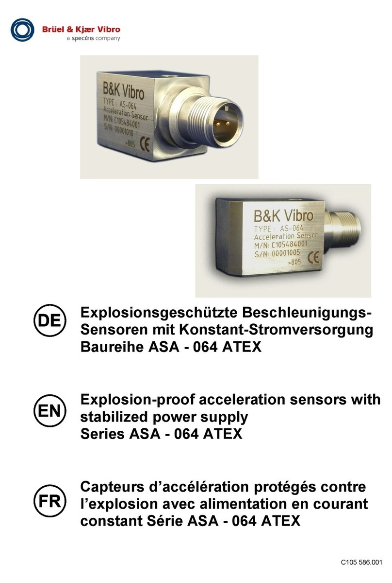
Spectris Bruel & Kjaer Vibro ASA-064 Series User manual
Spectris
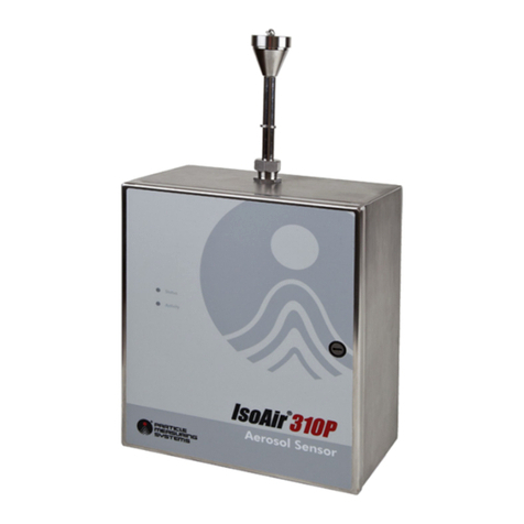
Spectris Particle Measuring Systems IsoAir 310P User manual

Spectris
Spectris Bruel & Kjaer Vibro 8315 User manual

Spectris
Spectris Bruel & Kjaer Vibro AS-477 User manual

Spectris
Spectris Bruel & Kjaer Vibro AS-668 User manual

Spectris
Spectris Bruel & Kjaer Vibro AS-247 User manual
Spectris
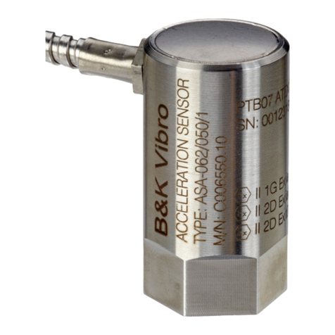
Spectris Bruel & Kjaer Vibro ASA-062 ATEX Series User manual
Spectris
Spectris Bruel & Kjaer Vibro ASA-068/200/0 User manual

Spectris
Spectris Bruel & Kjaer Vibro AS-667 User manual
Spectris
Spectris Particle Measuring Systems Airnet II 4-CH User manual
