exemys EGW1-MB-HT User manual

Rev. 3

Rev. 3
INDEX
INDEX _________________________________________________________________________ 2
1 INTRODUCTION _____________________________________________________________ 3
1.1 Purpose of the manual __________________________________________________________ 3
1.2 Product Overview ______________________________________________________________ 3
1.3 Orderin Codes ________________________________________________________________ 3
1.4 Technical Specifications _________________________________________________________ 4
2 INSTALLATION ______________________________________________________________ 5
2.1 Connectin the power supply ____________________________________________________ 5
2.2 Serial Port Wirin s _____________________________________________________________ 5
2.3. HART Ports ___________________________________________________________________ 6
2.4. LEDS Indicators ________________________________________________________________ 9
3 CONFIGURATION ___________________________________________________________ 10
3.1 Network Confi uration _________________________________________________________ 10
3.2 Confi uration web pa e ________________________________________________________ 11
3.3 Modbus Confi uration _________________________________________________________ 12
3.4 HART Confi uration ___________________________________________________________ 13
3.5. Administrator Settin s _________________________________________________________ 13
3.6. WEB Monitorin ______________________________________________________________ 14
4 MODBUS REGISTERS _________________________________________________________ 16
5 MONITORING, MANUAL SENDING, HART OVER TCP _______________________________ 18
5.1 Data Monitorin ______________________________________________________________ 18
5.2 Manual sendin of HART commands ______________________________________________ 18
5.3 Transparent Mode (HART over TCP) ______________________________________________ 19
A COMMAND CONSOLE _________________________________________________________ 20
B IP ADDRESS USING ARP PROTOCOL ______________________________________________ 22
C FACTORY SETTINGS ___________________________________________________________ 24
D DIN RAIL MOUNTING _________________________________________________________ 25
E EGW1-MB-HT with PACTware© in transparent mode _______________________________ 26

Rev. 3
1INTRODUCTION
1.1 Purpose of the manual
This manual provides the instructions for easy and quick installing and operating of the EGW1-MB-
HT. The manual starts with a general description of the product, following the instructions for the
correct hardware installation. Configuration and operation of the device is detailed below.
1.2 Product Overview
E W1-MB-HT module is a device used to connect any instrument with HART communication to one
or more Modbus Masters, Modbus TCP or Modbus Serial (RTU / ASCII).
Device has 3 independent Modbus ports. One Ethernet for Modbus TCP, one RS232 and the other
RS485 opto-isolated for Modbus RTU / ASCII
1.3 Orderin Codes
Orderin Code Description
E W1-110-3-IA3-MB-HT
(3) HART ports / (1) RS232 port / (1) RS485 opto
-
isolated port
(1) Ethernet port 10/100 Mbps

Rev. 3
1.4 Technical Specifications
Technical Specification
Network Protocols
Modbus TCP, TCP / IP, DNS, HTTP, DHCP, ICMP, ARP, SNMP
Network Port
Ethernet 10 / 100 Mbps, RJ45 Connector
Serial Protocol
Modbus RTU, Modbus ASCII
Serial Port
(1) RS232 port / (1) RS485 opto-isolated port
Pluggable Terminal Block connection
Supported devices
Any HART Device
Device Mana ement
HTTP Server, password protected
RS-232 Serial Console
Firmware Update
From Web Page
Led Indicators
Status, Data / Link
Measurements
100mm x 22,5mm x 112mm (Height x Width x Length)
Power Supply
10 to 30 VDC
Consumption
12VDC 80mA/ 24VDC50mA
Temperatures
Operation Temperature: -15°C to 65 °C
Storage Temperature: -40°C to 75 °C
Warranty
1 Year
Technical Support Included

Rev. 3
2INSTALLATION
2.1 Connectin the power supply
E W1-MB-HT allows a power supply from +10 to 30 VDC. Positive power supply must be connected
to terminal N° 1 and negative power supply to terminal No. 2 as shown in the following figure:
2.2 Serial Port Wirin s
E W1-MB-HT has two serial ports; one of them is RS232 (Port A), used as a Modbus slave and as a
configuration port through the serial (Appendix A), and other one RS485 (Port B) used as Modbus
Slave.
2.2.1. RS232 port wirin (Port A)
To connect the device RS232 serial port to PC serial port or any other serial device to set and
monitor, it must be connected as can be shown in the following figure. You should consider E W1-
MB-HT is a DTE device, that means it must cross wire with those of the PC.
2.2.2. RS485 port wirin (Port B)
To connect the device RS485 opto-isolated serial port to any serial device, it must be connected as
can be shown in the following figure. The operation of this port is independent of the RS232. An
isolated ND terminal is available in the terminal if an RS485 cable with mesh wire is used.

Rev. 3
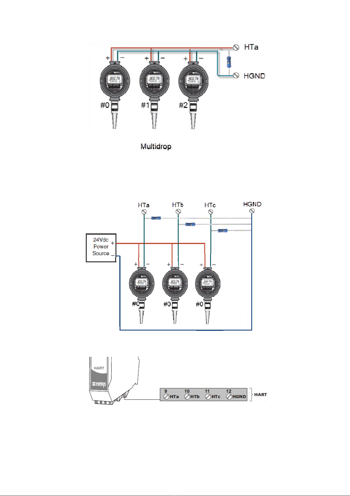
2.3. HART Ports
E W1-MB-HT has three HART ports: HTa, HTb and HTc. All the three ports share
the H ND terminal to close the loop.
One or more HART instruments can be connected to each port. To connect two or
more instruments, they must be configured in MULTIDROP mode and denote a different HART
address to each one.
Each loop must be closed with an external resistance of 250 ohms. The resistance must dissipate a
power equivalent to the square of the maximum current of each instrument multiplied by the value
of the resistance.
= ( ) 250 ℎ
Example, for 3 instruments generating up to 4 mA in Multidrop mode:
= (3 4) 250 ℎ = 36
Connection diagram for3 transmitters in Multidrop mode to the HTa port
Three 250 ohm 250 mW resistors of are provided to the user together with the device

Rev. 3
2.2.1 One passive transmitter to HTa port wiring diagram
2.2.2 One active transmitter to HTa port wiring diagram
2.2.3 Three passive transmitters to HTa port in Multidrop mode wiring diagram
Rev. 3
2.2.4 Three active transmitters to HTa port in Multidrop mode wiring diagram
2.2.5 Three passive transmitters to in NO Multidrop mode to ports HTa, HTb and HTc wiring
diagram

Rev. 3
2.4. LEDS Indicators
E W1-MB-HT has three LEDs, two of them on the Ethernet connector, the yellow one shows the
connection to the network, while the green one indicates the status of the Modbus TCP
connection.
The Power LED indicates device is on.
Green
Yello
w
Description
- Continuously on Looking for a DHCP server.
-
1/2
second on and
1/2
second
off. Waiting for configuration ping and / or waiting serial console.
-
90% of a second off and the
remaining time on.
Device has an IP address and a connection
bearer link. This is the
normal operating state
-
10% of a second off and the
remaining time on.
It has no IP address and cannot find the DHCP server. It will
search the DHCP server for in 60 seconds.
- Flashing very fast
Lack of Ethernet link
(Cable disconnected).
On
-
Modbus TCP connection set.
Flashing off
-
Transmission or reception of data
.
Flashing alternatively with
Yellow LED
Flashing alternately with the
reen LED Critical Failure. Contact technical support

Rev. 3
3CONFIGURATION
3.1 Network Confi uration
E W1-MB-HT configuration is done through a configuration web page connecting the device to
the Ethernet network on which it is going to work.
To access to the configuration web page, you must connect E W1-MB-HT to ethernet network
and install Exemys Device Locator software.
Download the Exemys Device Locator:
http://www.exemys.com/beta/software/edl_setup.exe
Once the device is connected, this will search for a DHCP server to obtain an IP address
automatically. We will search for it using the Exemys Device Locator software, which allows us
searching, identifying and configuring the basic network parameters. The rest of the configuration
is done from the configuration web page of the device.
In case you do not have a DHCP server, the Exemys Device Locator will find the device with
IP address 0.0.0.0, as shown in the figure below.
If you do not have a DHCP server, give it an IP address using the Exemys Device Locator
button or using the methods explained in Appendix B.
The Exemys Device Locator buttons are:
Query Network: Searches for all connected EXEMYS devices on the same network.
Properties ...: Configuring Network Parameters (IP Address, Network Mask, ateway)
Confi ure...: Direct access to the configuration web page.

Rev. 3
3.2 Confi uration web pa e
Once the E W1-MB-HT has a valid IP address, you can access the web page to configure the other
parameters (If your web browser is configured to search for a proxy server, disable this option)
Type the E W1-MB-HT IP address in the address field of your browser or from the Exemys Device
Locator, press the Configure button.
If you configured a password, the computer will ask for it when entering the web page.
In this case, you must enter "admin" as the user and then the password that was set.
If you want to change it, you can do it from the Administrator menu
Rev. 3
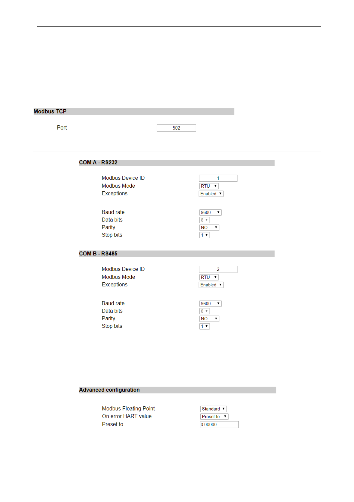
3.3 Modbus Confi uration
E W1-MB-HT has an internal Modbus slave containing the values of all HART devices configured.
This slave can be accessed by multiple means of communication: Ethernet (Modbus TCP), RS232
and RS485 (Modbus RTU or ASCII)
Modbus TCP
The only possible configuration is to define the connection port of the Modbus TCP slave. The TCP
slave responds to all IDs and responds to exceptions
Serial Ports RS232/RS485
Advance Confi uration
It is possible to determine some specific parameters of the Modbus map so that it adapts to our
needs.
Among the different configurations we have, the order of the floating-point values, if they are
placed in one direction or another.

Rev. 3
Another characteristic is to define the behavior in case of failure, if the connected device has a
malfunction, we can determine in the values of the Modbus map a behavior that is defined in 3
options: Keep the last value read, show NaN or a predefined value that is useful.
3.4 HART Confi uration
Basic Configuration
We can define the number of retries on the HART ports.
Table of device
It is the table that tells us which devices we have connected and which short address they have.
Each port has its table. It is important not to repeat addresses in the same port.
3.5. Administrator Settin s
In the Administrator menu you can find device administration tools.

Rev. 3
Password
The web page and the configuration by Exemys Device Locator can be protected with a password.
This password can also be set from the Exemys Console (see Appendix A).
It only admits alphanumeric characters. The user to enter when asked is "admin".
To delete the password, only an empty password must be saved.
Restart
If necessary, the device can be restarted. In this way all your connections will be closed and all
your tasks will start again as if the device had just been energized.
Restore factory settings
The user can return the device to its original factory settings. This option can be executed from the
web page or from the Exemys Console (see Appendix A).
Firmware Update
The device's firmware can be updated in case new versions with improvements arise.
By pressing the Update button, the web page will request you select the update file.
Then press the Download button and through informative messages you can follow the update
process.
The device will restart and be ready to operate again after the download.
3.6. WEB Monitorin
It allows to show the status of the HART variables; this is possible by blocks of 4 sensors according
to port and sensors.
Colors indicate the status, gray inactive, red is active but in failure (communication problems) and
white indicates that the sensor is responding correctly.

Rev. 3
Rev. 3
4MODBUS REGISTERS
The values read from HART devices are available in HOLDIN RE ISTER and INPUT RE ISTER area.
For each HART device, 20 registers are reserved.
Registers of the HART PORT A first device
The registers of HART PORT A second device can be found from the register 40021/30021
The registers of HART PORT B firstdevice can be found from the register 40321/30321
The registers of HART PORT C firstdevice can be found from the register 40641/30641
tatus Registers of each HART device in each port
HART
Address
HART A
HART B
HART C
1 40001 40321 40641
2 40021 40341 40661
3 40041 40361 40681
4 40061 40381 40701
5 40081 40401 40721
6 40101 40421 40741
7 40121 40441 40761
8 40141 40461 40781
9 40161 40481 40801
10 40181 40501 40821
11 40201 40521 40841
12 40221 40541 40861
13 40241 40561 40881
14 40261 40581 40901
15 40281 40601 40921
16 40301 40621 40941
Holdin
Re ister
Input
Re ister Value Format
40001 30001 Estado
0: f
ail or disabler disabled
1: HART OK
40002 30002 reserved -
40003 – 40004 30003 – 30004 Current [mA] Float
40005 – 40006 30005 – 30006 1st variable Float
40007 – 40008 30007 – 30008 2nd variable Float
40009 – 40010 30009 – 30010 3rd variable Float
40011 – 40012 30011 – 30012 4th variable Float
40013 – 40020 30013 – 30020 reserved -

Rev. 3
Value to add to the tatus Register address of each device
Example:
To read the 2nd variable of the device number 8 connected to the HART Port C
40781+7=40788
Add
Val
ue
Format
+0
Status
*
0 / 1
+3
C
u
rrent [mA]
F
lo
at
+5
1st variable
Flo
at
+7
2nd variable
Flo
at
+9
3rd variable
Flo
at
+11
4th variable
Flo
at

Rev. 3
5MONITORING, MANUAL SENDING, HART OVER TCP
5.1 Data Monitorin
E W1-MB-HT allows to monitor the communication between the device and the HART
transmitters connected to its ports.
For this you must set a TCP connection to port 999 with some TCP client terminal software (for
example Putty or HyperTerminal)
Once the connection is established, you will see the data sent by the device through its three ports
(A>, B>, C>) and the responses of the transmitters (<) expressed in hexadecimal. In the event that
a HART transmitter does not respond, the text "Timeout" will be displayed.
A> FF FF FF FF FF FF FF 02 00 00 00 02
<-Timeout
C> FF FF FF FF FF 82 62 E6 D7 18 49 03 00 83
<- FF FF FF FF FF 86 22 E6 D7 18 49 03 15 00 41 40 63 33 34 2D 00 00 00 00 20 41 95 33 30 29 C1 20 00 00 A5
5.2 Manual sendin of HART commands
This function allows to send HART frames manually. This allows to make adjustments in the
configuration of the HART transmitters once they are already installed in the field.
For this you must establish a TCP connection to port 998 with some TCP client terminal software
(for example Putty or HyperTerminal)
When connecting to port 998, the user must select the HART port to which it wishes to send the
manual command by pressing the letters A, B or C.
Select HART port A, B or C
Then the user must write the frame to be sent in hexadecimal text and press ENTER (ASCII 13)
upon completion. It is not necessary to write the 0xFF codes of the preamble or add the CRC at the
end because it is calculated automatically.
The frame sent will be sandwiched between regular read queries.
Example 1: Send the command 00 (read unique identifier) to a HART transmitter with short
address 00 on the HART port C.
Select HART port A, B or C
Port C
02 00 00 00 ->
<- FF FF FF FF FF 06 00 00 0E 00 41 FE 62 E6 05 05 01 01 08 00 D7 18 49 BD
Example 2: Send command 15 (read output information) to a HART transmitter with long address
62E6-D71849 on the HART port A.

Rev. 3
Select HART port A, B or C
Port A
82 62 E6 D7 18 49 0F 00 ->
<- FF FF FF FF FF 86 22 E6 D7 18 49 0F 13 00 41 01 00 2D3F 80 00 003F 00 00 0100
0000 00FB 62 AD
5.3 Transparent Mode (HART over TCP)
This function allows the E W1-MB-HT to be used as a HART converter over TCP to HART. This
allows the configuration software of each transmitter to be used remotely, arriving at the location
through a TCP connection. Probably it is necessary to use a virtual COM port software (such as
Serial IP) to get from the software to E W1-MB-HT.
•Each device HART port has an assigned TCP port assigned to the transparent mode. Port
HART A: 10001, Port HART B: 10002, Port HART C: 10003
•The device will stop sending its own HART queries, while the connection to this port lasts
•The communication in transparent mode cannot be monitored on port 999
•No additional byte type is added to the frame
Please refer to Appendix E to see how to do it using PACTware.

Rev. 3
A. COMMAND CONSOLE
EGW1-MB-HT can be set through a command console connecting the device to a serial port on the
PC.
To access the command console, you must connect the EGW1-MB-HT to a RS232 port on a PC and
you must install an Exemys serial terminal program, called Exemys Console.
Download the Exemys Console:
http://www.exemys.com/console
Once the serial terminal program is installed, connect the EGW1-MB-HT to a RS232 port on the PC
and execute the Exemys Console.
1. Click on Connection -> Serial Port, it will open a window with name of all COM Serial port.
Select with double click the port where device is connected. Verify Baud rate in the serial por
is 9600.
2. Turn on the EGW1-MB-HT and in the first 7 seconds type CF and press ENTER or press the
CF button. EGW1-MB-HT will display a welcome message on the configuration command
console.
Other manuals for EGW1-MB-HT
2
Table of contents


