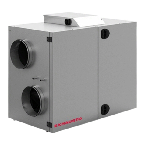
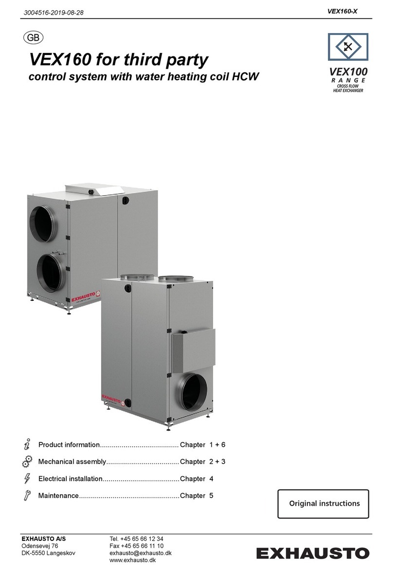
Exhausto VEX150CF H User manual

VEX150CF for third party
control system with water heating coil HCW
Product information............................................................... Chapter 1 + 6
Mechanical assembly............................................................ Chapter 2 + 3
Electrical installation.............................................................. Chapter 4
Maintenance.......................................................................... Chapter 5
Original instructions
3005724-2023-03-30
EXHAUSTO A/S
Odensevej 76
DK-5550 Langeskov
Tel. +45 65 66 12 34
Fax +45 65 66 11 10
www.exhausto.dk

1. Product information
1.1. Designations used in these instructions..............................................................................................6
1.1.1. Designations used in these instructions..........................................................................................6
1.2. Application.............................................................................................................................................. 6
1.3. Location requirements........................................................................................................................... 6
1.3.1. Space requirements........................................................................................................................7
1.3.2. Requirements for underlying surface.............................................................................................. 7
1.3.3. Condensation outlet........................................................................................................................ 8
1.3.4. Requirements for duct system........................................................................................................ 8
1.4. Description.............................................................................................................................................. 9
1.4.1. Horizontal VEX - design..................................................................................................................9
1.4.2. Vertical VEX - design.....................................................................................................................11
1.4.3. Parts of the VEX unit.....................................................................................................................12
1.5. Principal dimensions, Horizontal VEX................................................................................................12
1.6. Principal dimensions, Vertical VEX.....................................................................................................14
2. Handling
2.1. Unpacking............................................................................................................................................. 17
2.2. Transport............................................................................................................................................... 17
2.2.1. Transport of Horizontal air handling units..................................................................................... 17
2.2.2. Transport of Vertical air handling units..........................................................................................18
2.2.3. Passage through openings........................................................................................................... 19
2.2.4. Internal transport with reduced weight.......................................................................................... 20
3. Mechanical assembly
3.1. Installation of Horizontal and Vertical VEX........................................................................................ 24
3.1.1. Installation directly on floor........................................................................................................... 24
3.1.2. Installation on mounting base....................................................................................................... 24
3.2. Condensation outlet............................................................................................................................. 24
3.2.1. Establishment of condensation outlet........................................................................................... 24
3.3. Water heating coil.................................................................................................................................26
3.3.1. Principles for connecting the water heating coil............................................................................26
3.3.2. Bleeding of coils............................................................................................................................27
3.3.3. MVM valve.................................................................................................................................... 28
4. Electrical installation
4.1. Electrical installation............................................................................................................................29
5. Maintenance, hygiene and servicing
5.1. Maintenance.......................................................................................................................................... 30
5.1.1. Overview of maintenance intervals............................................................................................... 30
5.2. Hygiene (VEX100VDI only)...................................................................................................................30
5.3. Servicing and cleaning.........................................................................................................................31
5.3.1. Filter replacement......................................................................................................................... 31
5.3.2. Cleaning the fans.......................................................................................................................... 31
5.3.3. Cleaning the heating coils.............................................................................................................31
5.3.4. Removing and cleaning the counterflow heat exchangers........................................................... 31
5.3.5. Cleaning the counterflow heat exchanger.....................................................................................32
5.4. Airflow measurement........................................................................................................................... 33
5.4.1. Determining airflow and pressure................................................................................................. 33
6. Technical data
6.1. Weight, corrosion class, temperature ranges, etc.............................................................................36
6.2. Panel filters........................................................................................................................................... 37
6.3. Water heating system...........................................................................................................................38
6.4. Capacity diagram..................................................................................................................................38
6.5. EC Declaration of Conformity..............................................................................................................38
6.6. Ordering spare parts............................................................................................................................ 38
3005724-2023-03-30
2/40

Symbols, terms and warnings
Prohibition symbol Failure to observe instructions marked with a prohibition symbol may result in
serious or fatal injury.
Danger symbol Failure to observe instructions marked with a danger symbol may result in per-
sonal injury and/or damage to the unit.
Scope This instruction manual is for use with EXHAUSTO VEX-type air handling units. Please refer to the
product instructions regarding accessories and extra equipment.
The instructions must be fully observed to ensure personal safety and to protect the equipment and
ensure its correct operation. EXHAUSTO A/S accepts no liability for accidents caused by equipment
not used in accordance with the manual’s instructions and recommendations.
Supply air/extract
air
This instruction manual uses the following terminology:
● Supply air
● Extract air
● Outdoor air
● Exhaust air
Accessories The confirmation of order states which accessories are delivered with the VEX unit.
Lock the air han-
dling unit during
operation
The VEX unit must always be locked during op-
eration:
● Use the cylinder lock in the handle. Re-
member to remove the key from the lock.
● Or use a padlock. Use the handle’s built-in
padlock fixture
Lock
Padlock fitting
Warnings:
Opening the air
handling unit
Do not open the service doors until the supply voltage has been disconnected at
the isolation switch and the fans have stopped.
Prohibited uses The VEX unit is not to be used to transport solid particles or in areas where there
is a risk of explosive gases.
No duct connection If one or more of the spigots is not connected to a duct: Fit a protective net to the
spigots with a maximum mesh width of 20 mm (in accordance with EN294).
3005724-2023-03-30
4/40

Information plate The VEX unit rating plate shows:
● VEX unit, type (1)
● production number (2)
1
2
NB: Always have the production number ready when contacting EXHAUSTO A/S.
3005724-2023-03-30
5/40

1. Product information
1.1 Designations used in these instructions
1.1.1 Designations used in these instructions
The simplified diagram shows a VEX unit with LEFT fan placement.
Component Function
BP1 Bypass motor
HCW Water heating coil
LS (F) Closing damper, outdoor air
LS (A) Closing damper, exhaust air
MC1 Motor controller 1 for extract air motor
MC2 Motor controller 2 for supply air motor
M1 Extract air motor
M2 Supply air motor
P1.2X and P1.2Y Points for measuring pressure rise across extract air fan
P2.2X and P2.2Y Points for measuring pressure rise across supply air fan
P2.1X and P2.1Y Points for measuring pressure loss across outdoor air filter
P1.1X and P1.1Y Points for measuring pressure loss across extract air filter
1.2 Application
Comfort ventilation EXHAUSTO VEX is used for comfort ventilation tasks.
Operating temperature range for the unit – see section "Technical data".
Prohibited uses The VEX unit is not to be used to transport solid particles or in areas where there is a risk of explosive
gases.
1.3 Location requirements
Location The air handling unit is designed for indoor fitting.
3005724-2023-03-30 Product information
6/40

Outdoor VEX100H:The VEX100 horizontal model can be ordered for outdoor installation, in which case it is pro-
vided with a cover (accessory VEX100OD).
1.3.1 Space requirements
The drawings below show how much space is needed for opening the doors and servicing the air handling
unit, e.g. changing filters, cleaning, servicing, etc.
NB: For servicing, the VEX must have a free height of at least 300 mm above the connection box. (For
Vertical: For servicing, the VEX must have a free height of at least 300 mm in front of the connection
box.
Horizontal VEX
1590
735
RD13895-01
785
Vertical VEX
735
785
RD13896-01
1.3.2 Requirements for underlying surface
Horizontal and Ver-
tical VEX
When floor-mounting the unit, the surface must be:
3005724-2023-03-30 Product information
7/40

● flat
● level (+/- 3 mm per metre)
● hard
● resistant to vibration
1.3.3 Condensation outlet
A condensation outlet must be installed in the immediate vicinity of the unit. See also "Mechanical assem-
bly" section.
1.3.4 Requirements for duct system
Connection to duct
system
To achieve maximum performance and minimal energy consumption, the unit should be connected to a
straight duct at least 750 mm long, before and after the unit.
Silencers The duct system must be fitted with silencers specified by the Project Manager, which meet the re-
quirements of the operating area.
Insulation The duct system must be insulated against:
● condensation
● sound
● thermal loss
Condensation Condensation in the ducts may occur when the exhaust/outdoor air has high humidity. EXHAUSTO
recommends a condensation outlet is also fitted at the lowest point in the ducts.
Outdoor air intake The outdoor air intake must be dimensioned with sufficiently low airflow to prevent rain and snow being
drawn into the duct system.
No duct connection If one or more of the spigots is not connected to a duct: Fit a protective net to the
spigots with a maximum mesh width of 20 mm.
3005724-2023-03-30 Product information
8/40

1.4 Description
1.4.1 Horizontal VEX - design
VEX unit construc-
tion
The following drawings show an overview of the design of left and right models of VEX units (shown
without door).
1,1,A
2,1,A
1,2,A
2,2,A
1
2
3
6
710
12
16
17 18
11
13
15
19
89
5
14
4
RD13921-01
Left
2,1,A
1,2,A
2,2,A
1
2
3
6
710
12
16
1718
11
13
15
19
89
5
14
4
1,1,A
RD13922-01
Right
3005724-2023-03-30 Product information
9/40

Pos. Function
1 Spigot 2.1.A Outdoor air spigot The spigot can also be positioned on the top
of the air handling unit (2.1.B).
2 Closing damper LS Closing damper, outdoor air, LSF (accessory)
3 Outdoor air filter Filters outdoor air
4 Bypass damper For operation with heat recovery, the bypass damper is closed
so that the air passes through the counterflow heat exchanger.
For bypass operation, the damper is open, and the air bypasses
the heat exchanger
5 Measurement socket Measurement socket for pressure loss across the filters
6 Spigot 1,1,A Extract air spigot
7 Condensation outlet Channels condensate to the drain
8 Extract air filter Filters extract air
9 Counterflow heat ex-
changer
Conducts heat from extract air to supply air
10 Condensation tray Collects the condensate and drains it away from the cross-flow
heat exchanger to the condensation outlet
11 Water heating coil with
bleed screw
Heats supply air if heat recovery is insufficient.
12 Spigot, 2,2,A Supply air spigot. The spigot can also be positioned at the bot-
tom of the air handling unit (2.2.B)
13 Supply air fan For outdoor air/supply air
14 Measurement socket Measurement socket for airflow calculation.
15 Extract air fan For exhaust air/extract air
16 Closing damper LS Closing damper – exhaust air, LSA (accessory)
17 Spigot 1,2,A Extract air spigot The spigot can also be positioned on the top of
the unit (1.2.B).
18 Connection box Positioning of terminal board for electrical connection
19 Extraction plate Positioning of motor controls
3005724-2023-03-30 Product information
10/40

1.4.2 Vertical VEX - design
VEX unit construc-
tion
The following drawings show an overview of the design of left and right models of VEX units (shown
without door).
1,1,B 2,1,B
1,2,B
2,2,B
13
4
5
6
13
16
9
17
11 12
7
8
10
15
2
14
18
1920
RD13923-01
Left
1,1,B
2,1,B
1,2,B 2,2,B
13
4
5
6
13
16
9
17
1112
RD13924-01
7
8
10
15
2
14
18
19 20 Right
3005724-2023-03-30 Product information
11/40

Pos. Part Function
1 Outdoor air filter Filters outdoor air
2 Bypass damper For operation with heat recovery, the bypass damper is closed
so that the air passes through the counterflow heat exchanger.
For bypass operation, the damper is open, and the air bypasses
the heat exchanger
3 Condensation tray Collects the condensate and drains it away from the cross-flow
heat exchanger to the condensation outlet
4 Condensation outlet Channels condensate to the drain
5 Extract air filter Filters extract air
6 Spigot 1.1.B Extract air spigot
7 Measurement socket Measurement socket for pressure loss across extract air filter
8 Counterflow heat ex-
changer
Conducts heat from extract air to supply air
9 Water heating coil with
bleed screw
Heats supply air if heat recovery is insufficient.
10 Spigot 2,2,B Supply air spigot. The spigot can also be positioned on the top of
the air handling unit (2.2.A).
11 Supply air fan For outdoor air/supply air.
12 Extract air fan For exhaust air/extract air
13 Spigot 1,2,B Extract air spigot The spigot can also be positioned on the top of
the unit (1,2,A).
14 Closing damper LS Closing damper – exhaust air, LSA (accessory)
15 Measurement socket Measurement socket for airflow calculation.
16 Connection box Positioning of terminal board for electrical connection
17 Extraction plate Positioning of motor controls
18 Closing damper LS Closing damper, outdoor air, LSF (accessory)
19 Spigot 2,1,B Outdoor air spigot The spigot can also be positioned at the bot-
tom of the air handling unit (2.1.A)
20 Measurement socket Measurement socket for pressure loss across outdoor air filter
1.4.3 Parts of the VEX unit
Cabinet The inside and outside of the cabinet are made of Aluzinc® The cabinet has been insulated with 50
mm mineral wool.
Fans The unit contains two centrifugal fans with backward curved blades for extract air and supply air.
Counterflow heat
exchanger
The counterflow heat exchanger in the unit is mounted with a modulating bypass damper. The counter-
flow heat exchanger can be removed and cleaned.
Filters The unit includes integral panel filters for both extract air and supply air.
1.5 Principal dimensions, Horizontal VEX
VEX150H, Left The following drawing gives the principal dimensions:
3005724-2023-03-30 Product information
12/40

1458
62 1600 62
325
602 426
265
1,2,B 2,1,B
95 **
1,2,A
2,2,A
2,2,B
1,1,A
2,1,A
DN32
325
318
12
337
1137
518
O
400
O
400
518
318
785
418
12
307
1193
418
418
391
34
O400
O
400
835*
½"
MN
1,2,A
2,2,A
2,1,A
1,1,A
N
M
RD13878-01
593 122
62
602
62
1553
NB: The drawing shows all of the spigot positioning options.
* Allow a distance for service in front of the unit equivalent to the unit depth.
** Allow a min. of 300 mm free height for service.
VEX150H, Right The following drawing gives the principal dimensions:
3005724-2023-03-30 Product information
13/40
62160062
325
602426
265 1,2,B
2,1,B
95 **
1,2,A
2,2,A
2,2,B
1,1,A
DN32
325
½"
1458
318
12
337
1137
518
518
318
12
307
1193
418
418
391
34
O
400
1,2,A
2,2,A
2,1,A
1,1,A
593122
62
602
785
418
835*
2,1,A
O400
O400
O
400
1553
62
MN
N
M
RD13879-01
NB: The drawing shows all of the spigot positioning options.
* Allow a distance for service in front of the unit equivalent to the unit depth.
** Allow a min. of 300 mm free height for service.
1.6 Principal dimensions, Vertical VEX
VEX150V, Left The following drawing gives the principal dimensions:
3005724-2023-03-30 Product information
14/40
2,2,A
1,2,A
2,1,A
N
M
M
N
1,2,A
O
400
2,2,A
2,2,B 1,2,B
62
1,1,B 2,1,B
518
325
518
318
O
400
O400
318
2,1,A
785
835*
½"
RD13880-01
62 1450
391
1181
418
36
1287
14
279
1287
584 426
304
1612
62
1125
594
716
590
DN32
62
418
95**
418
NB: The drawing shows all of the spigot positioning options.
* Allow a distance for service in front of the unit equivalent to the unit depth.
** Allow a min. of 300 mm free height for service.
VEX150V, Right The following drawing gives the principal dimensions:
3005724-2023-03-30 Product information
15/40

1,2,A 2,2,A
2,2,B
1,2,B
62
1,1,B
2,1,B
2,1,A
½"
36
1287
14
279
1287
584 426
304
1612
62
DN32
95**
2,1,A
O
400
621450
391
1181
418
62
418
2,2,A
1,2,A
518
325
518
318
318
785
835*
1125
594
716
590
O
400
O400
418
RD13881-01
N
M
M
N
NB: The drawing shows all of the spigot positioning options.
* Allow a distance for service in front of the unit equivalent to the unit depth.
** Allow a min. of 300 mm free height for service.
3005724-2023-03-30 Product information
16/40

2. Handling
2.1 Unpacking
Delivery The following components are supplied:
● VEX unit
● Accessories supplied
Packaging The unit is delivered on a disposable pallet and packed in clear plastic.
NB Once the plastic has been removed, the unit must be protected against dirt and dust:
●The covers on the spigots must not be removed until the spigots are connected to the ven-
tilation ducts.
●Whenever possible, keep the unit closed during fitting.
The unit should be
cleaned before it is
used.
Once the VEX unit is fitted, it must be checked and thoroughly cleaned. All dust, debris and metal
shavings must be vacuumed up.
2.2 Transport
Transport Transport the VEX unit on the disposable pallet. Do not lift it with the spigots or connection box.
2.2.1 Transport of Horizontal air handling units
Transport methods Transport the VEX unit in one of the following ways:
Method Drawing
Manual transport:
Lifting brackets for manual transport can
be fitted as shown on the drawing:
3005724-2023-03-30 Handling
17/40

Method Drawing
Pallet truck or fork-lift truck:
Lift the VEX unit on the disposable pallet.
IMPORTANT: If the disposable pallet
cannot be used, the forks on the lifting
equipment must be long enough to pre-
vent damage to the bottom of the unit.
RD10248-01
Crane:
Never lift the VEX unit with
the lifting brackets by us-
ing a crane.
Use straps and lifting yokes to prevent
damage to the unit.
RD13391-01
2.2.2 Transport of Vertical air handling units
Transport methods Transport the VEX unit in one of the following ways:
Method Drawing
Manual transport:
Lifting brackets for manual transport can
be fitted as shown on the drawing:
RD11116-02
RD11117-02
3005724-2023-03-30 Handling
18/40

Method Drawing
Using pallet truck or fork-lift truck:
Lift the VEX unit on the disposable pallet.
IMPORTANT: If the disposable pallet
cannot be used, the forks on the lifting
equipment must be long enough to pre-
vent damage to the bottom of the unit.
RD10536-02
Crane:
Never lift the VEX unit with
the lifting brackets by us-
ing a crane.
Use straps and lifting yokes to prevent
damage to the unit.
RD13392-01
Weight For information about the weight of the unit, see the section "Technical specifications".
2.2.3 Passage through openings
Height Horizontal VEX: 1557 mm + any spigot in bottom (+62 mm).
Vertical VEX: 1612 mm + any spigot in top (+62 mm) and bottom (+62 mm).
Width The list below shows how wide the opening has to be for the VEX unit to pass through:
If the opening width is* Then
less than 785 mm the unit will not pass through.
785–835 mm remove doors, see relevant section.
greater than 835 mm the unit can pass through.
* Measurements are based on the exact dimensions of the air handling unit
3005724-2023-03-30 Handling
19/40

2.2.4 Internal transport with reduced weight
Weight reduction The air handling unit's weight can be reduced during transport by removing service doors, fans and
counterflow heat exchanger. The table below shows how much weight can be reduced by removing the
various parts.
Parts Weights, VEX150CF
Fan, 2 items at 20 kg = 40 kg
Counter flow heat exchangers, 1 item at 31 kg
Doors, 2 items at 26 kg = 52 kg
Total weight 330 kg
3005724-2023-03-30 Handling
20/40
Other manuals for VEX150CF H
1
Table of contents
Other Exhausto Control System manuals

Exhausto
Exhausto VEX370H User manual

Exhausto
Exhausto EXact2 HMI2-350-TOUCH Installation guide

Exhausto
Exhausto EXact2 HMI2-350-TOUCH Installation guide

Exhausto
Exhausto EXact2 VEX240 series Installation guide

Exhausto
Exhausto EXact Installation guide

Exhausto
Exhausto VEX260HX User manual

Exhausto
Exhausto VEX200 series Installation guide

Exhausto
Exhausto VEX320CX User manual

Exhausto
Exhausto EFC 25 Manual

Exhausto
Exhausto VEX160 Series User manual