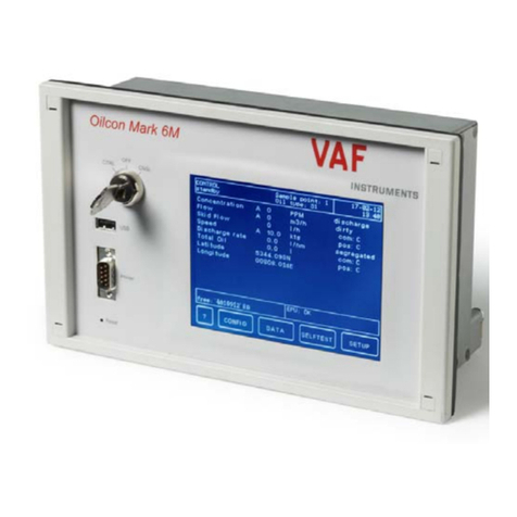
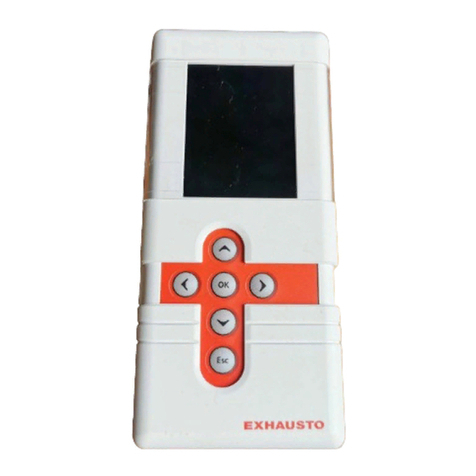
Exhausto EXact2 HMI2-350-TOUCH Installation guide

EXact2 HMI2-350-TOUCH Control
System
Basic instructions for VEX308
Original instructions
3006401-2022-05-04
EXHAUSTO A/S
Odensevej 76
5550 Langeskov, Denmark
Tel.: +45 65 66 12 34
Fax: +45 65 66 11 10
www.exhausto.dk

Symbols and software version
Symbols used in these instructions.................................................................... 4
Software version.................................................................................................... 4
Software version ............................................................................................. 4
1. Menu structure
Overview of menus and user levels..................................................................... 5
2. User mode
Operation................................................................................................................ 6
Use of control icons in the menus....................................................................6
Overview of HMI icons...........................................................................................7
3. Technician and service levels
3.1. Access codes for technician and service menus............................................... 9
Menu 3.2 - Selecting language............................................................................10
Menu 3.2.1 - Setting date and time..................................................................... 10
Menu 3.2 - Reset settings....................................................................................10
Menu 3.2 - Reload database................................................................................ 11
Menu 3.6 - Web server......................................................................................... 11
Menu 3.7 - Backup/restore.................................................................................. 12
3.2. IMPORTANT when servicing...............................................................................12
3.2.1. Connect service panel....................................................................................14
4. Starting up the unit for operation
4.1. Getting started..................................................................................................... 15
4.1.1. Menu 3.3 - VEX configuration........................................................................ 15
Menu 3.4 - Accessories..................................................................................16
4.2. De-icing method ..................................................................................................17
4.2.1. Bypass de-icing - example.............................................................................17
4.3. Temperature controlled frost protection -- choice of method......................... 18
Menu 3.5 - BMS............................................................................................. 18
Menu 3.5 - BMS............................................................................................. 19
4.4. What is an indoor air quality level?....................................................................19
Operation with CO2B, PIRB and RHB .......................................................... 20
Menu 1 - Selecting operating mode................................................................... 20
Menu 3.1.1 - Operating settings - Air regulation............................................... 21
Menu 3.1.1 - Operating settings Balance.......................................................21
Menu 3.1.1.5 Regulators ...............................................................................22
Menus 3.1.1.1.1 to 3.1.1.1.4 Configuring the selected indoor air quality levels
......................................................................................................................................23
Menu 3.1.1.1.x - Air set point ........................................................................ 23
Menu 3.1.1.1.x - Temperature set point ........................................................ 23
Menu 3.1.1.1.x - Absolute / Relative temperature .........................................23
Menu 3.1.1.1.x - Cooling relative start .......................................................... 24
Menu 3.1.1.1.x - Heating relative start .......................................................... 24
Menu 3.1.1.1.x - Cooling absolute start ........................................................ 24
Menu 3.1.1.1.x - Heating absolute start ........................................................ 25
Menu 3.1.1 - Operation settings - Temperature regulation.............................. 25
Compensation...................................................................................................... 26
Menu 3.1.2 - Air compensation........................................................................... 26
Menu 3.1.2.1 - CO2 compensation ............................................................... 26
Menu 3.1.2.2 - Humidity compensation of airflow ......................................... 27
Menu 3.1.2.3 - Airflow reduction ................................................................... 28
Menu 3.1.2.4 - Outdoor compensation of airflow .......................................... 29
Menu 3.1.3 - Temperature compensation.......................................................... 30
Outdoor air temperature compensation (menu 3.1.2.1) ................................30
Summertime compensation (menu 3.1.2.2) ..................................................31
Menu 3.1.4 + Menu 8.1 - Filter (monitoring with hour counter) ..................... 31
Menu 3.1.5 - Night-time cooling .................................................................... 32
Menu 3.1.6 - Cold recovery............................................................................34
Menu 3.1.7 - Fan limits...................................................................................34
Menu 3.1.8 - Temperature limits for supply air and room...............................34
Room temperature limits................................................................................35
3006401-2022-05-04
2/72

Menu 5 - Time and weekly plan.......................................................................... 35
Menu 5.1 - Date and time...............................................................................35
Menu 5.2 - Weekly plan ................................................................................ 36
Menu 7 - Safety functions................................................................................... 37
Menu 7.1 - Fire alarm.....................................................................................37
Menu 7.2 - Frost protection of HCW ............................................................. 38
Menu 7.3 - Frost protection heat exchanger ................................................. 39
5. Operation
Menu 2 - Operating readings.............................................................................. 41
Menu 2.1 - Air temperatures ......................................................................... 41
Menu 2.1.1 - Set points for regulators ...........................................................42
Menu 2.3 - Motor controller parameters (MC parameters) ............................42
Menu 2.4 - Temperature regulating units ...................................................... 42
Menu 2.6 - Heating unit .................................................................................42
Menu 2.8 - CCW cold water coil ....................................................................43
Menu 2.9 - CU cooling unit.............................................................................43
Menu 2.10 - MXCU external cooling unit....................................................... 43
Menu 2.11 - CO2/RH sensors (if mounted)....................................................44
Menu 6 - Versions................................................................................................ 44
Menu 8 - Service...................................................................................................44
Connect service panel....................................................................................46
Menu 8.2 - VDI 6022 (not applicable)............................................................ 47
Menu 8.3 - Forced start .................................................................................47
Menu 8.3.1 Fans............................................................................................ 47
Menu 8.3.3 Heating unit.................................................................................47
Menu 8.3.3 Cooling unit (not applicable)........................................................47
Menu 8.3.4 Dampers and relays....................................................................48
6. Alarms
6.1. Alarms and info (Menu 4).................................................................................... 49
6.2. Reset alarms.........................................................................................................49
6.3. Alarm display – causes of errors....................................................................... 50
6.4. List of alarms........................................................................................................51
Appendix 1 - Simplified diagrams
Simplified diagrams.............................................................................................68
VEX308 with water heating coil HCW ...........................................................68
VEX308 with electric heating coil HCE ......................................................... 69
Appendix 2 - Temperature resistance table
Temperature resistance table DC95................................................................... 70
3006401-2022-05-04
3/72

Symbols and software version
Symbols used in these instructions
Prohibition symbol Failure to observe instructions marked with a prohibition symbol
may result in serious or fatal injury.
Danger symbol Failure to observe instructions marked with a danger symbol
may result in personal injury and/or damage to the unit.
Software version
Software version
This manual applies from the following version:
AHUC: 3.11.1.0
HMI: 4.1.0.0
3006401-2022-05-04 Symbols and software version
4/72

1. Menu structure
Overview of menus and user levels
User menu: Technician and service menu:
23°C
60%
Select menu by using
arrow up and
arrow down keys.
Activate by pressing
on menu.
Press return arrow
to switch between
the user and
technician menu,
or to exit the menu.
Main menu
Operating mode >
Operating readings >
Settings >
Alarm and info >
Time and weekly plan >
Versions >
Safety functions >
Service >
Save settings >
1 Operating mode
Operation > Manual
2 Operating readings
Air temperature >
Airflows >
MC parameters >
Temp. reg. units >
Pressure >
Heating coil >
CH cooling unit >
CCW
CU cooling unit >
MXCU
MXHP
Timers >
CO2/RH sensorer >
3 Settings
Unit >
General >
Configuration >
Accessories >
BMS >
Web server >
Backup/restore >
4 Alarm and info
Information
Alarm
Warning
Reset alarms >
Current list >
Alarm log list >
Delete alarm log >
Yes
No
No
No
No
5 Time and weekly plan
Date and time >
Weekly plan >
6 Versions
PO Number >
Hardware >
Software >
About EXact >
1234567
7 Safety functions
Fire alarm >
Frost protection HCW >
Frost protection HR >
CH cooling unit >
8 Service
Filter >
VDI 6022 >
Forced start >
Calibration of MPT >
Light > Off
9 Save settings
Save settings >
Last saved:
Date
Time
No
xx.xx.xxxx
xx:xx.xx
Ventilation
60
Set temperature
23°C
3006401-2022-05-04 Menu structure
5/72

2. User mode
Operation
Use of control icons in the menus
HMI - Human Machine Interface panel
Control icon Used for...
Menu icon
Navigation arrows up and down as well as setting val-
ues.
Approve icon for selection.
Undo icon.
Switch between daily user menu and technician/serv-
ice menu.
Exit a menu without making changes
3006401-2022-05-04 User mode
6/72

Overview of HMI icons
Icon Description
Manual operation
Timer overridden until next changeover in the timer schedule
Timer, current indoor air quality level is comfort
Timer, current indoor air quality level is economy
Timer, current indoor air quality level is standby
Timer, VEX/CX has stopped
Timer, no changeover times defined in timer schedule
BMS-controlled operation
Externally-controlled operation
Setpoint for temperature shown in °C
Setpoint for ventilation shown as percentage: 0% = no ventilation OFF
= Unit is switched off - timer operation cannot start up unit
BMS or Web server-controlled system overrides the OFF func-
tion. This means the system may start up even if set to OFF
The unit is running de-icing (De-ice)
Unit alarm. Contact the service technician who can help reset the
alarm. Icon is also shown in the technician menu
Warning. Contact the service technician who can help reset the warn-
ing. Icon is also shown in the technician menu
Temporarily
in service
Service display connected
3006401-2022-05-04 User mode
7/72

Icon Description
External start/stop disconnected. See Electrical Installation Guide for
further information
Summertime
Wintertime
No communication on the external BUS, or communication between the
VEX/CX and HMI is disconnected
Fire!
Fire alarm. Closed circuit open and the pre-set fire alarm function acti-
vated
Loading Linux...
Startup: Web server accessing database. The icon is displayed until the
HMI panel is ready for use.
3006401-2022-05-04 User mode
8/72

3. Technician and service levels
3.1 Access codes for technician and service menus
Step Action The display shows
1 If the display is in stand-by: Press the
display to activate full light.
Press the menu icon
2 Press the number in the code row to acti-
vate and select the number via the up/
down arrows
When the whole number code has been
selected, approve with
● The code for technician mode is1111
(some menus are hidden or read-on-
ly). EXHAUSTO recommends this
mode be used for normal service
tasks
● The code for the specialist level is
3142 (full access to all menus).
NB: incorrect settings
(wrong values) may have a nega-
tive impact on unit operation in
some menus
0
0 0 00
Password
1
1 1 11
Password
3
Press the up/down arrow
keys to find and select the desired func-
tion in the main menu.
Main menu
Operating mode
Operating readings
Settings
NB:
● Automatically logs out and returns to the user menu if no buttons are press-
ed in a five-minute period
3006401-2022-05-04 Technician and service levels
9/72

Menu 3.2 - Selecting language
The HMI is factory set to English – another language can be selected by:
Step Action
Unit >
General >
Configuration >
Accessories >
BMS >
Web server >
Backup/restore >
3 Settings
3.2 General
Date and time >
Language >
Reset settings >
Reload database >
English
Main menu
Operating mode >
Operating readings >
Settings >
Alarm and info >
Time and weekly plan >
Versions >
Safety functions >
Service >
Save settings >
1 Select "Settings"
2 Select "General"
3 Select the required language in line 2 "Language"
4 Return to the main menu and select yes in "Save settings"
Menu 3.2.1 - Setting date and time
Step Action
Unit >
General >
Configuration >
Accessories >
BMS >
Web server >
Backup/restore >
3 Settings
3.2 General
Date and time >
Language >
Reset settings >
Reload database >
English
3.2.1 Date and time
Date > 22-02-2009
Day >
Time >
Wednesday
13:11
1 Select"Settings"
2 Select "General"
3 Select "Date and time" to set these parameters in Menu 3.2.1
4 Return to the main menu and select yes in "Save settings"
Menu 3.2 - Reset settings
Selecting "Reset settings" resets the user settings. See the menu guide for details of
which menus are affected.
NB: This cannot be undone and the VEX/CX restarts.
3006401-2022-05-04 Technician and service levels
10/72

3.2 General
Date and time >
Language >
Reset settings >
Reload database >
English
Menu 3.2 - Reload database
Selecting "Reset settings" resets the user settings. See the menu guide for details of
which menus are affected.
Database reloads
Waiting for
data...
Loading DB values
Menu 3.6 - Web server
Contact the network administrator for information on the correct IP address, etc. If
the admin password is lost, it can be reset to the factory setting. But note that this
cannot be reversed. See EXact web server instructions.
No
> 192.168.001.180
> 255.255.255.000
> 192.168.001.001
80
00:1F:79:00:00:D0
No
3.6 Web server
DHCP >
IP address
Subnet mask
Standard gateway
Port number >
MAC address
Reset password >
3006401-2022-05-04 Technician and service levels
11/72

Menu 3.7 - Backup/restore
It is recommended that a backup copy of the VEX/CX settings is made and saved in
a secure location. See the individual backup guidelines in the diagram:
+
Backup via the HMI panel
● Insert the USB plug in one of the web
server sockets
● Select menu 3.7 Backup/restore
● It can take up to 20 seconds before the
connection to the USB is established;
data will be lost if the process is inter-
rupted.
The backup file can only be saved on a
USB plug. Once the file has been saved it is
not possible to change the file name or type.
The file is named automatically as in this ex-
ample: backup_20110918.file
Backup via web server
Follow the backup/restore instructions in the
web server guide. The backup file may be
saved on any medium (USB, PC etc.).
A backup file saved via the web server may
be renamed, but the file type cannot be
changed.
Note:
If a backup file has been saved from the
web server and then renamed, it cannot be
retrieved (restored) via HMI until the name
has been changed back to the standard
form, see "Via HMI panel".
If it is necessary to make backup files for
several VEX/CX, it is recommended that
each file is saved on a separate USB stick,
or to create one folder per VEX /CX in which
the backup files are saved.
3.2 IMPORTANT when servicing
The VEX door must be opened to allow servicing and cleaning.
Disconnect the power by removing the plug from the socket before
opening the door.
The fan motors will run on for up to 5 minutes.
NB Do not use aggressive cleaners or abrasive/sharp objects for
cleaning.
3006401-2022-05-04 Technician and service levels
12/72

RD13235-01
Weekly plan It is important to set ventilation to OFF when the weekly plan is
active:
Set ventilation to OFF
Note - If the HMI panel shows 0% (VEX/CX
is inactive) and the unit is operating to a
weekly plan when servicing begins, there
is a risk that the program may be changed
by timer operation and re-start the VEX
unit.
21°C
0%
● Log on to technician menu, using password
1111
● Change to manual operation via menu 1
● Change back to user menu
● The icon for manual operation appears in
the right-hand corner of the menu
● Press the ventilation icon
● Set the ventilation to 0% using the arrows
● Press approve
23°C
0%
● OFF will now appear on the display next to
the ventilation icon
23°C
OFF
BMS unit or Web
server
If the VEX/CX is controlled via a BMS or Web server,
these controls could override the OFF function and the
VEX/CX may start up irregularly. To disconnect the BMS
or WEB server connection, you must remove the plug
from the EXact2 main board. Refer to the section on the
terminal board in the Electrical Installation Guide.
3006401-2022-05-04 Technician and service levels
13/72

3.2.1 Connect service panel
When connecting the service panel you are recommended to use an extra HMI panel
connected to the VEX at the connection box.
NB: The socket on the side of the VEX is only meant for the service HMI. For perma-
nent connection of the HMI, use the external bus connector on the EXact2 main
board.
EXact2 main board
Cable requirements The service panel cable can be ordered from EXHAUSTO (product number:
HMI2SERVICEC).
3006401-2022-05-04 Technician and service levels
14/72

4. Starting up the unit for operation
The Modbus connectors must not be connected or removed while the
units are powered up. Both Modbus units must be switched off before
making changes, otherwise the units may be damaged.
During commissioning, it may be necessary to work with the control
system boxes open. Components in these boxes must only be
touched with electrically-insulated tools.
Before doing any work on motor controls or motor cables and termi-
nal boxes, the power supply must be switched off for at least five mi-
nutes to allow the capacitors to discharge.
Before any commis-
sioning begins
● Check that the supply voltage is connected
● Set the HMI panel to specialist mode. See section "Access codes for technician
and service menus"
4.1 Getting started
4.1.1 Menu 3.3 - VEX configuration
Type >
Size >
Orientation
Exchanger
3.3 Configuration
300
8
C
Type K
Line in Menu 3.3 Factory-set and should not be changed.
VEX type x
VEX size x
Orientation x
3006401-2022-05-04 Starting up the unit for operation
15/72

Menu 3.4 - Accessories
Ice-detect. >
De-icing method >
Heating coil >
Cooling unit >
Power step HCE >
Filter detect. >
PIR >
TS >
CO2 >
RH >
Dining solution >
3.4 Accessories
Tice
6
None
None
4
Timer
None
None
None
None
No
AUX OUT setting > 1
Line in Menu 3.4 Factory-set and
should not be
changed.
Comments
Ice detection method ● Tice
De-icing method Selected automatically:
● Method 4, if a heating coil
is present
● Method 6, if no heating
coil is present
Heating unit Options:
● None
● MHCW (Water heating
coil)*)
● MHCE (Electric heating
coil)
● IHCW (set at the factory
for the the EXact2 main
board, if the VEX was
purchased with HCW)
*) Not applicable to VEX308
Cooling unit*) Options:
● None*)
● MXCU (external cooling
unit)*)
● CCW (cold water coil)*)
● CU (EXHAUSTO cooling
unit)*)
*) Not applicable to VEX308
Filter detection ● Hours
PIR Activating PIR sensor. Op-
tions:
● None
● PIR1 (MIOPIR connected)
● PIR2 (PIRB connected)
● Both (Both MIOPIR and
PIRB connected)
When the sensor(s) is/are acti-
vated by movement in the
room, the VEX will be overrid-
den and set to comfort level.
Comfort level will be main-
tained for the time set on the
rear of the sensor (PIRB), af-
ter which the VEX will return to
the previous indoor climate
level.
NB: The time interval for MIO-
PIR is a fixed 10 minutes and
cannot be changed).
3006401-2022-05-04 Starting up the unit for operation
16/72

Line in Menu 3.4 Factory-set and
should not be
changed.
Comments
TS Activation of external tempera-
ture sensor and selection of
type. Options:
● None
● TS ROOM
● TS DUCT*)
*) Not applicable to VEX308
CO2 Activation of CO2 sensor Op-
tions:
● None
● MIOCO2
● CO2B
● BMS
RH Activation of RH sensor. Op-
tions:
● None
● MIORH
● RHB
● BMS
4.2 De-icing method
4.2.1 Bypass de-icing - example
Extract
air
Supply
air
Exhaust
air
Outdoor
air
RD13238GB-01
+18°C 100% +14°C +20°C
+22°C
-10°C
80%
100%
100%
20%
+
Ventilator 1
Ventilator 2
+3°C
Detection meth-
od
Principle De-icing starts when...
Temperature con-
trolled
Temperature sensor Tice registers the temperature
in the heat exchanger and starts the de-icing proc-
ess when the indicated temperature is reached.
Temperature is below the set
value e.g. Tice < 0°C. (Menu 7.3)
3006401-2022-05-04 Starting up the unit for operation
17/72

4.3 Temperature controlled frost protection -- choice of method
RD13144GB-01
Heating coil
Yes No
METHOD 6
METHOD 4
The outdoor air gradually
bypasses the heat
exchanger
The outdoor air is
gradually reduced
The unit enters
hibernation mode
The unit starts every two
hours and monitors the
situation
The outdoor air is
gradually reduced
The unit enters
hibernation mode
The unit starts every two
hours and monitors the
situation
Air control method See section "Menu 3.1.1 Operating settings air control" for the air control method.
Start-up after hiber-
nation
The unit restarts after two hours of hibernation. If
● outdoor temperature is 2 Kelvin higher than when the unit went into hiberna-
tion, or
● if the temperature has risen above the level for activation of hibernation,
normal de-icing operation continues.
If neither of these two conditions are met within five minutes, the unit will enter hi-
bernation again.
Menu 3.5 - BMS
BMS >
Configuration >
3.5 BMS
None
Line in Menu 3.5 Comments
BMS Activating override control system BMS Op-
tions:
● None
● Modbus
● MTCP
● MLON
● BACnet MS
● BACnetIP
Configuration Configuration of Modbus and BACnet MSTP.
BMS configuration See detailed description in the instructions for the protocols.
3006401-2022-05-04 Starting up the unit for operation
18/72

Menu 3.5 - BMS
BMS >
Configuration >
3.5 BMS
None
Line in Menu 3.5 Remarks:
BMS Activating override control system BMS Op-
tions:
● None
● Modbus
● MTCP
● MLON
● BACnet MS
● BACnet IP
Configuration Configuration of Modbus and BACnet MSTP.
BMS configuration See detailed description in the instructions for the protocols.
4.4 What is an indoor air quality level?
Example
3.1.1.1.1 Comfort
Air setpoint >
Air setpoint,cool >
Temp. setpoint >
Abs. /Rel. >
Cool rel. start >
Cool abs. start >
Heat rel. start >
Heat abs. start >
60
80
21,0
Relativ
1,0
---
-1,0
---
%
%
°c
K
K
Menu screen Parameters such as ventilation and temperature set points and control method for
a given indoor air quality level are grouped in a menu, as shown in the example
above.
Indoor climate levels Energy sav-
ing
People in
the room
Air-replace-
ment*
Deviation from desired room
temperature*
(Ventilation stopped) - No No ventilation No control of room temperature
Economy Menu
3.1.1.1.3
Large No Low Greatest temperature deviation
permitted*)
Standby Menu 3.1.1.1.2 Small No Low Least temperature deviation per-
mitted*
Comfort Menu 3.1.1.1.1 None Yes High Precise temperature
Manual Menu 3.1.1.1.4 Dependent
on setting
Yes/No Adjustable Adjustable
* Air-replacement and temperature deviation set via the HMI panel.
3006401-2022-05-04 Starting up the unit for operation
19/72

The current indoor air quality level can be controlled in five ways:
● Via a weekly plan, based on the given operating requirements. Set via the HMI
panel.
● Via an HMI panel in the room.
● Via sensor(s) positioned in the room or in the extract air duct (e.g. MIO-PIR,
MIO-CO2, MIO-RH, MIO-TS)
● Via a PC connected to the built-in Web server
● via a high-level control system (e.g. a BMS unit)
NB: The Comfort indoor climate level is the overall indoor climate level. The comfort
level is also activated if a mounted PIR sensor gives a signal (the unit
changes from an energy-saving indoor climate level/OFF).
Operation with CO2B, PIRB and RHB
See "VEX 308 EXact Operating and Servicing Instructions" for more details of VEX
operation with the following sensors:
● Operation with CO2 (CO2B) and motion sensor (PIRB)
● Operation with humidity (RHB) and motion sensor (PIRB)
● Also operation without activation from sensors
Menu 1 - Selecting operating mode
1 Operating mode
Operation > Manual
Select If
Manual The unit is intended to always operate at the same indoor air quality
level (set in menu 3.1.1.1.4) and operation is controlled manually via
the HMI panel or the Web server
Timer The unit is controlled automatically via a fixed weekly plan
Note for manual When the unit is operating in Manual indoor climate level, the values set for the
temperature setpoint (Temp. setpoint) and Air setpoint are shown immediately in
the user menu.
3.1.1.1.4 Manual
Air setpoint >
Air setpoint,cool >
Temp. setpoint >
Abs. / Rel. >
Cool rel. start >
Cool abs. start >
Heat rel. start >
Heat abs. start >
60
80
21,0
Relativ
1,0
---
-1,0
---
%
%
°c
K
K
21°C
60%
3006401-2022-05-04 Starting up the unit for operation
20/72
Other manuals for EXact2 HMI2-350-TOUCH
1
Table of contents
Other Exhausto Control System manuals
Exhausto
Exhausto EXact2 VEX240 series Installation guide

Exhausto
Exhausto EXact2 VEX240 series User manual
Exhausto
Exhausto VEX150CF H User manual

Exhausto
Exhausto VEX260HX User manual
Exhausto
Exhausto VEX200 series Installation guide
Exhausto
Exhausto EBC11 User manual
Exhausto
Exhausto VEX370H User manual
Exhausto
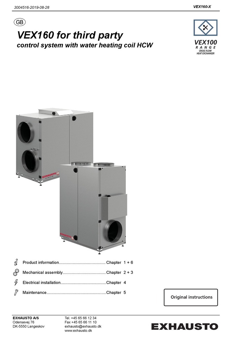
Exhausto VEX160 Series User manual

Exhausto
Exhausto VEX320C User manual

Exhausto
Exhausto EXact2 HMI2-350-TOUCH Installation guide
