Digitel MPC Manual Page 2 of 72
I. Contents
I. Introduction......................................................................................................................................... 6
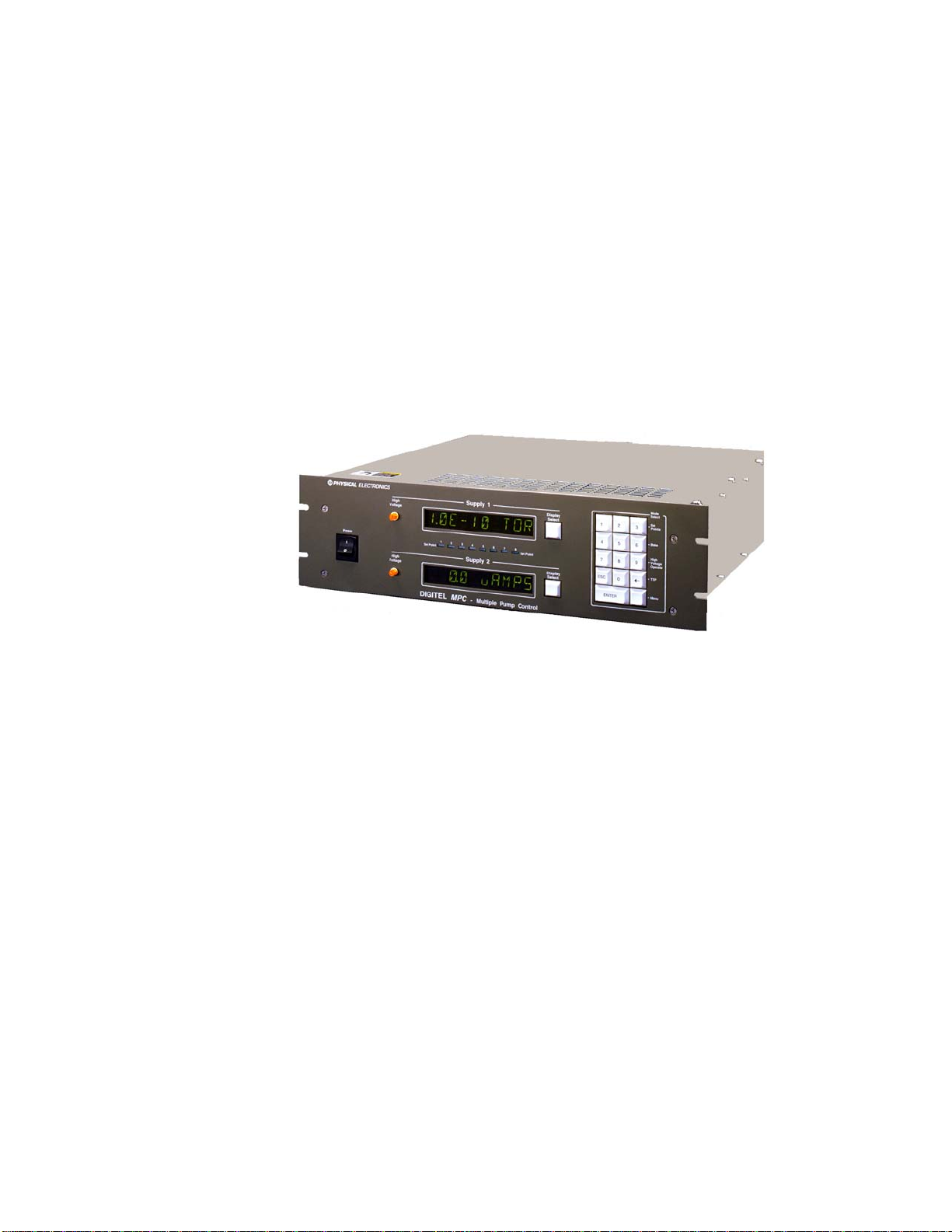
Description.............................................................................................................................................. 6
MPC Configurations........................................................................................................................... 6
RS-232/422/485 Serial Interface......................................................................................................... 6
Set Points ............................................................................................................................................ 6
High Voltage Modules........................................................................................................................ 7
Analog Outputs................................................................................................................................... 7
SAFE-CONN™ High-Voltage interlock............................................................................................ 7
AUTORUN™..................................................................................................................................... 7
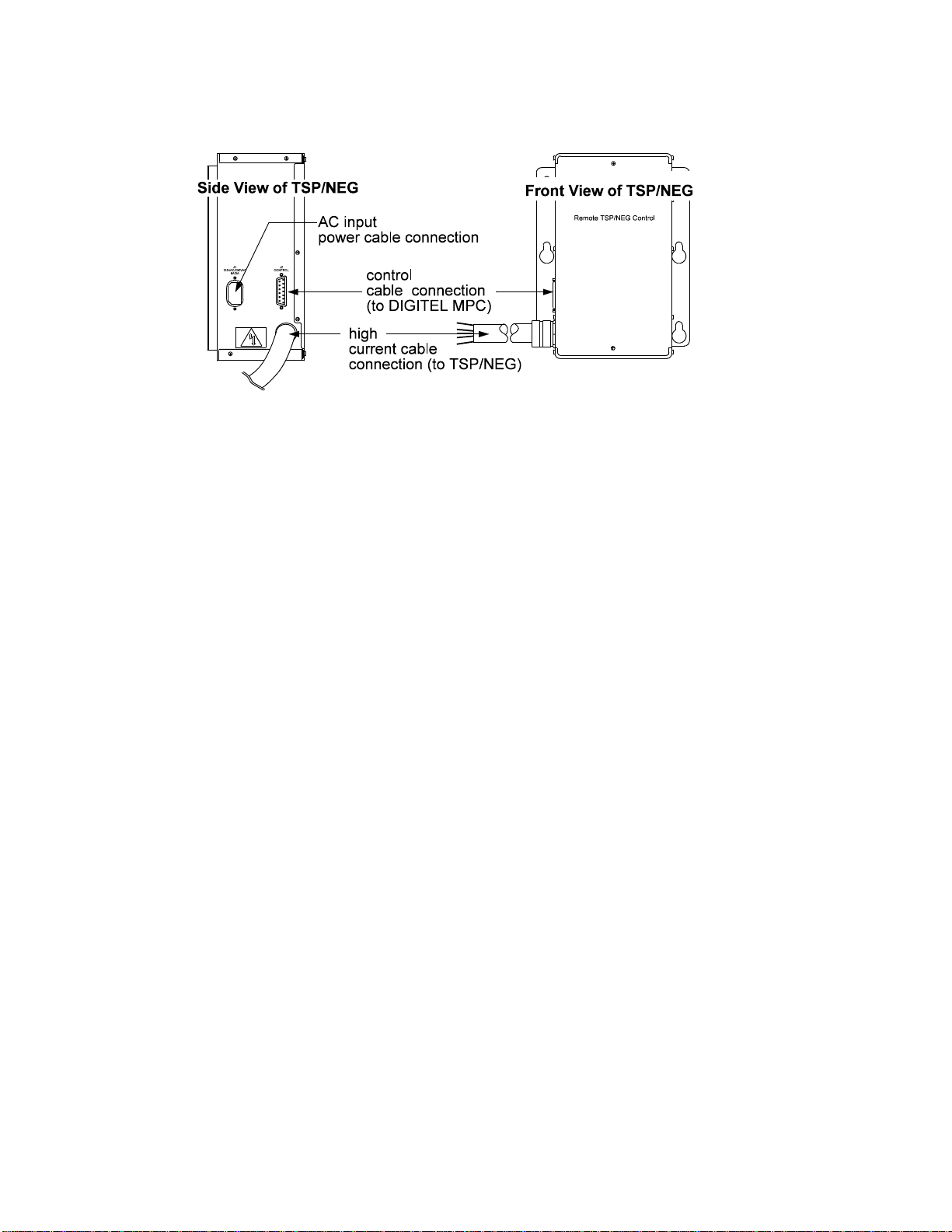
Remote TSP/NEG Control Option...................................................................................................... 7
High-Voltage/TSP Filament Interlock Option.................................................................................... 8
Specifications.......................................................................................................................................... 9
II. Installation......................................................................................................................................... 10
Inspection for Damage.......................................................................................................................... 10
Installing the DIGITEL MPC ............................................................................................................... 10
Required items.................................................................................................................................. 10
Procedure .......................................................................................................................................... 11
Installing the Remote TSP/NEG Control Option.................................................................................. 11
Required Items.................................................................................................................................. 12
Procedure .......................................................................................................................................... 12
SAFE-CONN™ Installation on an Ion Pump....................................................................................... 13
Required Items.................................................................................................................................. 13
Procedure .......................................................................................................................................... 13
III. Operation....................................................................................................................................... 15
Front Panel Description ........................................................................................................................ 15
Rear Panel Description ......................................................................................................................... 17
Operating the Ion Pump........................................................................................................................ 18
To Evacuate the Pump...................................................................................................................... 18
To Start the Pump ............................................................................................................................. 18
Using the Controls ................................................................................................................................ 19
Display Selection.............................................................................................................................. 19
Disable and Enable ........................................................................................................................... 19
Keypad.............................................................................................................................................. 19
Program Mode Keys......................................................................................................................... 21
Menu Key.......................................................................................................................................... 29
Display Messages.................................................................................................................................. 41
Event Log.............................................................................................................................................. 41
General Description.......................................................................................................................... 41
Front Panel Display of Events .......................................................................................................... 42
Serial Port Output of Events............................................................................................................. 42
Analog Outputs..................................................................................................................................... 43
Voltage measuring............................................................................................................................ 43
Current measuring............................................................................................................................. 43
High Voltage/TSP Filament Interlock Option...................................................................................... 44
Serial Interface...................................................................................................................................... 44
Standard ............................................................................................................................................ 44
Specifics............................................................................................................................................ 45
IV. Service........................................................................................................................................... 52