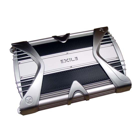
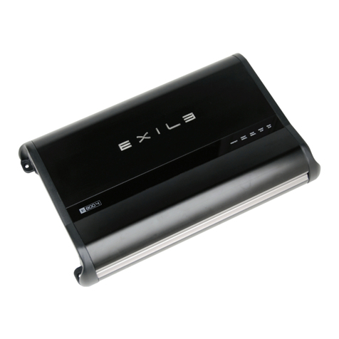
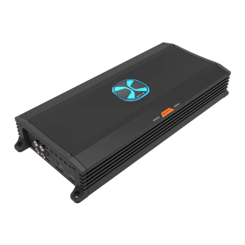
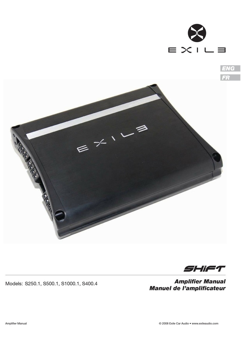
Exile XM20.1 User manual

AMPLIFIER
Owner’s Manual
Models:
XM12.1
XM20.1
XM15.4
XM30.2
JAVELIN

© 2015 Exile Audio • www.exileaudio.com Amplifier Manual
SPECIFICATIONS Multichannel
Amplier Class Class D
Frequency Response: 30 - 200Hz
Total Harmonic Distortion <0.5%
Signal to Noise Ratio: 92dB
Gain Range 0.2 - 6V
Low Pass Crossover Range 50 - 250Hz
Subsonic Crossover Range 15 - 250Hz
Bass Boost @ 45Hz: 0 to +18dB
Operational Eciency > 85%
Remote Bass Control Yes
Damping Factor: > 200
CEA-2006 Compliant Yes
SPECIFICATIONS Monoblock
Amplier Class Class D
Frequency Response: 30 - 200Hz
Total Harmonic Distortion < 0.5%
Signal to Noise Ratio: 92dB
Gain Range 0.2 - 6V
Low Pass Crossover Range 50 - 250Hz
Subsonic Crossover Range 15 - 250Hz
Bass Boost @ 45Hz: 0 to +18dB
Operational Eciency > 85%
Remote Bass Control Yes
Damping Factor: > 200
CEA-2006 Compliant Yes
XM12.1
Channels 1
Into 1 ohm 1200w x 1
Into 2 ohm 880w x 1
Fuse Size: 40A x 3
Power/Ground Wire Size: 4 Gauge
Dimensions: 15.0in L x 7.5in W x 2.3in H
XM15.4
Channels 4
Into 4 ohm 150w x 4
Into 2 ohm 225w x 4
In to 4 ohm Bridged 450w x 2
Fuse Size 40Ax2
Power/Ground Wire Size 4 AWG
Dimensions 12.7in L x7.5in W x 2.3in H
XM30.2
Channels 2
Into 4 ohm 300w x 2
Into 2 ohm 420w x 2
In to 4 ohm Bridged 840w x 1
Fuse Size 40Ax2
Power/Ground Wire Size 4 AWG
Dimensions 10.8in L x 7.5in W x 2.3in H
JAVELIN
Channels 5
Into 4 ohm 100w x 4
Into 2 ohm 150w x 4
In to 4 ohm Bridged 300w x 2
Into 2 ohm (Sub CH) 800w x 1
Into 4 ohm (Sub CH) 500w x 1
Fuse Size 40Ax3
Power/Ground Wire Size 4 AWG
Dimensions 15.0in L x 7.5in W x 2.3in H
Power Amplier XM SERIES
All amplifer power specications listed
are CEA-2006 compliant and have
been rated accordingly.
Ampliers were tested at 14.4V with
a 4 ohm load and ≤ 1% THD+N
XM20.1
Channels 1
Into 1 ohm 2000w x 1
Into 2 ohm 1700w x 1
Fuse Size: N/A
Power/Ground Wire Size: 4 Gauge
Dimensions: 17.5in L x 7.5in W x 2.3in H

© 2015 Exile Audio • www.exileaudio.com Amplifier Manual
JAVELIN 5 Channel Power Amplier
OUTPUT
Connect preamp signal cables from the head unit to
these terminals.
FRONT AND REAR
Connect preamp signal cables from the head unit to
these terminals.
GAIN
Used to reach maximum amplier power with a wide
variety of headunits.
HPF
Controls the high pass crossover point for the
speaker outputs.
LPF
Controls the low pass crossover point for the
speaker outputs.
BASS BOOST
Variable bass boost from 0 to +18dB @ 45 Hz.
CONFIG
2 - Set to 2 when only 1 RCA input is available from the source.
This drives all three channels from either the Front, Rear or
Sub input.
4 - Set to 4 when only the Front and Rear RCA inputs are availble
from the source. This drives the Front channel from the Front
RCA input and the Rear and Subwoofer channels from the
Rear RCA input.
6 - Set to 6 when all three, Front, Rear and Sub, RCA inputs
are available from the source. All channels have their own
specic input.
SUB
Connect subwoofer preamp signal cables from the head unit to
this terminal.
REMOTE
This port is for connecting the optional remote level control
(XMRB1). This allows up to 20dB of volume adjustment. This is
not a bass boost, it controls the level of the low pass signal.
POWER/PROTECT
Indicates if the amplier is working correctly (BLUE) or gone into
protect mode (RED).
SPEAKER OUTPUTS
Used to connect the amplier to the speakers. Use the
left channel positive (+) and the right channel negative (-) for
bridged mode.
12V+
This must be connected to the fused positive terminal (+12V) of
the car’s battery.
REMOTE
This must be connected to switched +12V, usually a trigger wire
coming from the head unit or ignition.
GND
This must be connected to the negative terminal of the car’s
battery or bolted to a clean, unpainted part of the chassis of
the vehicle.

© 2015 Exile Audio • www.exileaudio.com Amplifier Manual
2 Channel Power Amplier XM30.2
OUTPUT
Connect preamp signal cables from the head unit to
these terminals.
INPUT
Connect preamp signal cables from the head unit to
this terminal.
HPF
Controls the high pass crossover point for the
speaker outputs.
XOVER
HF - Sends high frequency signal to speakers.
FULL - Sends a full range signal to speakers.
LF - Sends low frequency signal to subwoofer.
LPF
Controls the low pass crossover point for the
speaker outputs.
BASS BOOST
Variable bass boost from 0 to +18dB @ 45 Hz.
GAIN
Used to reach maximum amplier power with a wide
variety of headunits.
POWER/PROTECT
Indicates if the amplier is working correctly (BLUE) or gone into
protect mode (RED).
SPEAKER OUTPUTS
Used to connect the amplier to the speakers. Use the
left channel positive (+) and the right channel negative (-) for
bridged mode.
FUSE
This amplier requires two 40A fuses.
12V+
This must be connected to the fused positive terminal (+12V) of
the car’s battery.
REMOTE
This must be connected to switched +12V, usually a trigger wire
coming from the head unit or ignition.
GND
This must be connected to the negative terminal of the car’s
battery or bolted to a clean, unpainted part of the chassis of
the vehicle.

© 2015 Exile Audio • www.exileaudio.com Amplifier Manual
XM15.4 4 Channel Power Amplier
OUTPUT
Connect preamp signal cables from the head unit to
these terminals.
INPUT (FRONT AND REAR)
Connect preamp signal cables from the head unit to
these terminals.
HPF
Controls the high pass crossover point for the
speaker outputs.
XOVER
HF - Sends high frequency signal to speakers.
FULL - Sends a full range signal to speakers.
LF - Sends low frequency signal to subwoofer.
LPF
Controls the low pass crossover point for the
speaker outputs.
BASS BOOST
Variable bass boost from 0 to +18dB @ 45 Hz.
GAIN
Used to reach maximum amplier power with a wide
variety of headunits.
POWER/PROTECT
Indicates if the amplier is working correctly (BLUE) or gone into
protect mode (RED).
REMOTE
This port is for connecting the optional remote level control
(XMRB1). This allows up to 20dB of volume adjustment. This is
not a bass boost, it controls the level of the low pass signal.
SPEAKER OUTPUTS
Used to connect the amplier to the speakers. Use the
left channel positive (+) and the right channel negative (-) for
bridged mode.
FUSE
This amplier requires two 40A fuses.
12V+
This must be connected to the fused positive terminal (+12V) of
the car’s battery.
REMOTE
This must be connected to switched +12V, usually a trigger wire
coming from the head unit or ignition.
GND
This must be connected to the negative terminal of the car’s
battery or bolted to a clean, unpainted part of the chassis of
the vehicle.

© 2015 Exile Audio • www.exileaudio.com Amplifier Manual
INPUT
Connect preamp signal cables from the head unit to
these terminals.
GAIN
Used to reach maximum amplier power with a wide
variety of headunits.
PHASE
Switches the output signal 180°.
SUBSONIC
Controls the highpass crossover point for the speaker outputs to
eliminate extreme low frequencies.
FREQ
Controls the lowpass crossover point for the
speaker outputs.
BASS BOOST
Variable bass boost from 0 to +12dB @ 45 Hz.
LPF
Variable bass boost from 0 to +12dB @ 45 Hz.
POWER/PROTECT
Indicates if the amplier is working correctly (BLUE) or gone into
protect mode (RED).
SPEAKER OUTPUTS
Used to connect the amplier to speakers. SM600.1 minimum
impedance of 2 ohm.
REMOTE
This port is for connecting the optional remote level control
(XMRB1). This allows up to 20dB of volume adjustment. This is
not a bass boost, it controls the level of the low pass signal.
FUSE
This amplier requires three 40A fuses.
12V+
This must be connected to the fused positive terminal (+12V) of
the car’s battery.
REMOTE
This must be connected to switched +12V, usually a trigger wire
coming from the head unit or ignition.
GND
This must be connected to the negative terminal of the car’s
battery or bolted to a clean, unpainted part of the chassis of the
vehicle.
Monoblock Power Amplier XM12.1

© 2015 Exile Audio • www.exileaudio.com Amplifier Manual
XM20.1 Monoblock Power Amplier
INPUT
Connect preamp signal cables from the head unit to
these terminals.
GAIN
Used to reach maximum amplier power with a wide
variety of headunits.
PHASE
Switches the output signal 180°.
SUBSONIC
Controls the highpass crossover point for the speaker outputs to
eliminate extreme low frequencies.
FREQ
Controls the lowpass crossover point for the
speaker outputs.
BASS BOOST
Variable bass boost from 0 to +18dB @ 45 Hz.
LPF
Low Pass Filter 25 to 250 Hz.
POWER/PROTECT
Indicates if the amplier is working correctly (BLUE) or gone into
protect mode (RED).
REMOTE
This port is for connecting the optional remote level control
(XMRB1). This allows up to 20dB of volume adjustment. This is
not a bass boost, it controls the level of the low pass signal.
SPEAKER OUTPUTS
Used to connect the amplier to speakers.
12V+
This must be connected to the fused positive terminal (+12V) of
the car’s battery.
REMOTE
This must be connected to switched +12V, usually a trigger wire
coming from the head unit or ignition.
GND
This must be connected to the negative terminal of the car’s
battery or bolted to a clean, unpainted part of the chassis of the
vehicle.

© 2015 Exile Audio • www.exileaudio.com Amplifier Manual
Marine Installation Guide POWERFLOW
Power Amplier XM SERIES
tower speakers
4ohm
2ohm
2ohm
Cabin
Amplifier Subwoofer
Amplifier
Tower
Amplifier
cabin speakers
subwoofer
Stereo
Battery Starting
Battery
Perko
Battery
Selector
Switch
ANL Fuse
Holder
2
2
1
1
L R L R
R L
1/0 ga.
4 ga.
Ground
Distribution
Block
MANL Fused
Power
Distribution
Block
InputInput
Input:
Source Unit
ZLD
zoned line driver
Aux Input:
phone/
mp3 player
R L R L
L RL R
XMRB1 Bass Control
111
SWITCH
L R
Input

© 2015 Exile Audio • www.exileaudio.com Amplifier Manual
Javelin Installation Diagram
System Includes:
1 Javelin
4 pr. Tower Speakers
1 Subwoofer
4 gauge power and ground required.
Front Left
Subwoofer
Left
Channel
RCA
Right
Channel
RCA
Remote
Bass Control
Front Right
Rear Left Rear Right
HPF Settings: For XM7 / SXT65 / SX65M:
Starting at 15Hz (fully turned counterclockwise),
turn the knob to 1 o’clock
1 o’clock
LPF Settings: For Subwoofer
Starting at 30Hz
(fully turned counterclockwise),
turn the knob to 11 o’clock
11 o’clock
Config Setting:
Set to 2
Use this setting when 1 input is available
from the source.
120W @ 2ohms 120W @ 2ohms
120W @ 2ohms
800W @ 2ohms 120W @ 2ohms
TERMINAL SIDE
SIGNAL SIDE
6 4 2
When you only have 1 set
of input RCA’s coming from
your source unit to the
Javelin amplier set the
Cong switch to “2”

© 2015 Exile Audio • www.exileaudio.com Amplifier Manual
Installation Diagrams Javelin
System Includes:
1 Javelin
4 pr. Tower Speakers
1 Subwoofer
4 gauge power and ground required.
Front Left
Subwoofer
Subwoofer Channel RCA’s
Left
Channel
RCA
Right
Channel
RCA
Remote
Bass Control
Front Right
Rear Left Rear Right
HPF Settings: For XM7 / SXT65 / SX65M:
Starting at 15Hz (fully turned counterclockwise),
turn the knob to 1 o’clock
1 o’clock
LPF Settings: For Subwoofer
Starting at 30Hz
(fully turned counterclockwise),
turn the knob to 11 o’clock
11 o’clock
Config Setting:
Set to 4
Use this setting when only 2 inputs (front &
sub) are available from the source.
120W @ 2ohms 120W @ 2ohms
120W @ 2ohms
800W @ 2ohms 120W @ 2ohms
TERMINAL SIDE
SIGNAL SIDE
6 4 2
When you have 2 sets of
input RCA’s coming from
your source unit to the
Javelin amplier set the
Cong switch to “4”

© 2015 Exile Audio • www.exileaudio.com Amplifier Manual
Javelin Installation Diagrams
System Includes:
1 Javelin
4 pr. Tower Speakers
1 Subwoofer
4 gauge power and ground required.
Front Left
Subwoofer
Subwoofer Channel RCA’s
Left
Channel
RCAs
Right
Channel
RCAs
Remote
Bass Control
Front Right
Rear Left Rear Right
HPF Settings: For XM7 / SXT65 / SX65M:
Starting at 15Hz (fully turned counterclockwise),
turn the knob to 1 o’clock
1 o’clock
LPF Settings: For Subwoofer
Starting at 30Hz
(fully turned counterclockwise),
turn the knob to 11 o’clock
11 o’clock
Config Setting:
Set to 6
Use this setting when all 3 inputs (front, rear
& sub) are available from the source.
120W @ 2ohms 120W @ 2ohms
120W @ 2ohms
800W @ 2ohms 120W @ 2ohms
TERMINAL SIDE
SIGNAL SIDE
6 4 2
When you have 3 sets of
input RCA’s coming from
your source unit to the
Javelin amplier set the
Cong switch to “6”

© 2015 Exile Audio • www.exileaudio.com Amplifier Manual
LIMITED WARRANTY
Exile warrants this product to be free from defects in material and workmanship under normal use for a period of one year from date of original purchase when
purchased from an Authorized Exile Dealer. If the product is labeled B Stock/Refurbished and purchased from an Authorized Exile Dealer, it is warranted for 90
days from date of purchase, regardless of place of installation. Should service be necessary under this warranty for any reason due to manufacturing defect
or malfunction during the warranty period, Exile will replace or repair (at its discretion) the defective merchandise with equivalent merchandise at no charge.
Warranty replacements on B-Stock merchandise may have cosmetic scratches and blemishes. Discontinued products may be replaced with more current
equivalent products. This warranty is valid only for the original purchaser and is not extended to owners of the product subsequent to the original purchaser. Any
applicable implied warranties are limited in duration to a period of the express warranty as provided herein beginning with the date of the original purchase at
retail, and no warranties, whether express or implied, shall apply to this product thereafter. Some states do not allow limitations on implied warranties, therefore
these exclusions may not apply to you. This warranty gives you specic legal rights; however you may have other rights that vary from state to state. This
warranty is only valid within the USA, for warranties outside of the USA consult the appropriate international distributor.
PORTLAND, OR USA
WWW.EXILEAUDIO.COM
DESIGNED AND ENGINEERED IN THE USA
V3 040214
This manual suits for next models
5
Table of contents
Other Exile Amplifier manuals
