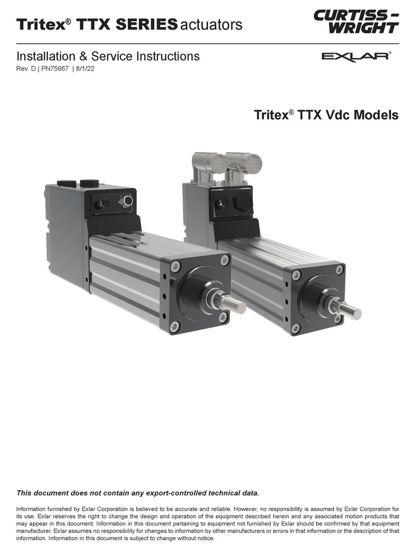
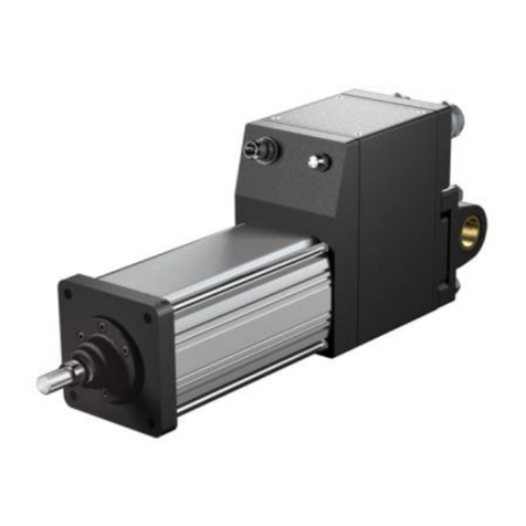
Exlar Tritex User manual

Tritex 1 Installation and Setup 109/27/12
PN: 27666 Exlar Corporation
Rev. M 952-500-6200M
LINEAR & ROTARY ACTUATOR
INSTALLATION, OPERATION AND SERVICE
MANUAL
Information furnished by EXLAR Corporation is believed to be accurate and reliable. However, no responsibility is assumed by
EXLAR Corporation for its use. EXLAR reserves the right to change the design and operation of the equipment described herein
and any associated motion products that may appear in this document. Information in this document pertaining to equipment not
furnished by EXLAR should be confirmed by that equipment manufacturer. EXLAR assumes no responsibility for changes to
information by other manufacturers or errors in that information or the description of that information. Information in this document is
subject to change without notice.

Tritex 1 Installation and Setup 209/27/12
PN: 27666 Exlar Corporation
Rev. M 952-500-6200M
Warranty and Limitation of Liability
Products are warranted for two years from date of manufacture as determined by the
serial number on the product label. Labels are generated and applied to the product at the
time of shipment. The first and second digits are the year and the third and fourth digits
represent the manufacturing week. Product repairs are warranted for 90 days from the
date of the repair. The date of repair is recorded within Exlar Corporation’s database
tracked by individual product serial number.
Exlar warrants its product(s) to the original purchaser and in the case of original
equipment manufacturers, to their original customer to be free from defects in material
and workmanship and to be made only in accordance with Exlar's standard published
catalog specifications for the product(s) as published at the time of purchase. Warranty or
performance to any other specifications is not covered by this warranty unless otherwise
agreed to in writing by Exlar and documented as part of any and all contracts, including
but not limited to purchase orders, sales orders, order confirmations, purchase contracts
and purchase agreements. In no event shall Exlar be liable or have any responsibility
under such warranty if the product(s) has been improperly stored, installed, used or
maintained, or if Buyer has permitted any unauthorized modifications, adjustments and/or
repairs to such product(s). Seller's obligation hereunder is limited solely to repairing or
replacing (at its opinion), at the factory any product(s), or parts thereof, which prove to
Seller's satisfaction to be defective as a result of defective materials, or workmanship and
within the period of time, in accordance with the Seller's stated product warranty (see
Terms and Conditions above), provided, however, that written notice of claimed defects
shall have been given to Exlar within thirty (30) days from the date of any such defect is
first discovered. The product(s) claimed to be defective must be returned to Exlar,
transportation prepaid by Buyer, with written specification of the claimed defect. Evidence
acceptable to Exlar must be furnished that the claimed defects were not caused by
misuse, abuse, or neglect by anyone other than Exlar.
Components such as seals, wipers, bearings, brakes, bushings, gears, splines, and
roller screw parts are considered wear parts and must be inspected and serviced on a
regular basis. Any damage caused by failure to properly lubricate Exlar products and/or to
replace wear parts at appropriate times, is not covered by this warranty. Any damage due
to excessive loading is not covered by this warranty.
The use of products or components under load such that they reach the end of their
expected life is a normal characteristic of the application of mechanical products.
Reaching the end of a product’s expected life does not indicate any defect in material or
workmanship and is not covered by this warranty.
Costs for shipment of units returned to the factory for warranty repairs are the
responsibility of the owner of the product. Exlar will return ship all warranty repairs or
replacements via UPS Ground at no cost to the customer.
For international customers, Exlar will return ship warranty repairs or replacements via
UPS Expedited Service and cover the associated shipping costs. Any VAT or local
country taxes are the responsibility of the owner of the product.

Tritex 1 Installation and Setup 309/27/12
PN: 27666 Exlar Corporation
Rev. M 952-500-6200M
The foregoing warranty is in lieu of all other warranties (except as Title), whether
expressed or implied, including without limitation, any warranty of merchantability, or of
fitness for any particular purpose, other than as expressly set forth and to the extent
specified herein, and is in lieu of all other obligations or liabilities on the part of Exlar.
Seller's maximum liability with respect to these terms and conditions and any resulting
sale, arising from any cause whatsoever, including without limitation, breach of contract or
negligence, shall not exceed the price specified herein of the product(s) giving rise to the
claim, and in no event shall Exlar be liable under this warranty otherwise for special,
incidental or consequential damages, whether similar or dissimilar, of any nature arising or
resulting from the purchase, installation, removal, repair, operation, use or breakdown of
the product(s) or any other cause whatsoever, including negligence.
The foregoing warranty shall also apply to products or parts which have been repaired
or replaced pursuant to such warranty, and within the period of time, in accordance with
Seller's stated warranty.
NO PERSON, INCLUDING ANY AGENT OR REPRESENTATIVE OF EXLAR, IS
AUTHORIZED TO MAKE ANY REPRESENTATION OR WARRANTY ON BEHALF OF
EXLAR CONCERNING ANY PRODUCTS MANUFACTURED BY EXLAR, EXCEPT TO
REFER PURCHASERS TO THIS WARRANTY.

Tritex 1 Installation and Setup 409/27/12
PN: 27666 Exlar Corporation
Rev. M 952-500-6200M
Safety Considerations
As with any electro-mechanical device, safety must be considered during the installation and
operation of your Tritex Series actuator. Throughout this manual you will see paragraphs
marked with CAUTION and WARNING signs as shown below
“Warning” indicates the information following is essential to avoiding a safety hazard.
“Caution” indicates the information following is necessary for avoiding a risk of damage
to the product or other equipment.
General
Failure to follow safe installation guidelines can cause death or serious injury. The voltages
used in the product can cause severe electric shock and/or burns and could be lethal.
Extreme care is necessary at all times when working with or adjacent to the product. The
installation must comply with all relevant safety legislation in the country of use. The forces
created by actuator could be lethal or cause severe injury if proper protection is not provided to
keep personnel away from moving components.
System Design and safety for personnel
The actuator is intended as a component for professional incorporation into complete
equipment or a system. If installed incorrectly, the actuator may present a safety hazard.
The actuator uses high voltages and currents, carries a high level of stored electrical energy,
and is used to control equipment which can cause injury. Close attention is required to the
electrical installation and the system design to avoid hazards either in normal operation or in the
event of equipment malfunction. System design, installation, commissioning and maintenance
must be carried out by personnel who have the necessary training and experience. They must
read this safety information and this manual carefully. None of the functions or features of
the Tritex actuator may be used to ensure safety of personnel, i.e. they must not be used
for safety-related functions. Careful consideration must be given to the functions of the
actuator which might result in a hazard, either through their intended behavior or through
incorrect operation due to a fault. In any application where a malfunction of the actuator or its
control system could lead to or allow damage, loss or injury, a risk analysis must be carried out,
and where necessary, further measures taken to reduce the risk- for example a failsafe brake in
case of loss of actuator braking power.
Never attempt to connect or disconnect the actuator with power applied. Dangerous
voltages are present. Damage to equipment and injury to personnel can result. Many
amplifiers have voltage present for a considerable time period after incoming power
is removed. Take care to insure that the amplifier has discharged all power.
In a domestic environment this product may cause radio interference, in which case
supplementary mitigation measures may be required.
WARNING
CAUTION
WARNING
WARNING
WARNING
WARNING

Tritex 1 Installation and Setup 509/27/12
PN: 27666 Exlar Corporation
Rev. M 952-500-6200M
Table of Contents
TRITEX™ PRODUCT OVERVIEW.................................................................................9
General Specifications........................................................................................................................11
Drive specifications for TRA500 remote option.......................................................................................11
Specifications: Size 20 Linear Actuators............................................................................................12
TLM20...............................................................................................................................................12
TSM20...............................................................................................................................................13
Specifications: Size 30 Linear Actuators............................................................................................14
TLM30...............................................................................................................................................14
TSM30...............................................................................................................................................15
Specifications: Size 60 Motors and Gear motors...............................................................................16
RTM060 ............................................................................................................................................16
RSM060 and RSG060.......................................................................................................................16
Specifications: Size 90 motors and Gear Motors...............................................................................18
RTM090 ............................................................................................................................................18
RSM090 and RSG090.......................................................................................................................18
Model Mask and Ordering Information...............................................................................................20
INSTALLATION............................................................................................................24
Mechanical Installation........................................................................................................................24
Lubrication.........................................................................................................................................24
Mounting Configurations....................................................................................................................24
Mounting and Operating Considerations............................................................................................24
General Operation.............................................................................................................................25
TLM & TSM Series Linear Actuator Anti-rotation Option.....................................................................25
TLM/TSM Anti-Rotate ..........................................................................................................................26
TLM20 Dimensions..............................................................................................................................27
TSM20 Dimensions..............................................................................................................................28
TLM30 Dimensions..............................................................................................................................29
TSM30 Dimensions..............................................................................................................................30
RTM060 and RTG060 Dimensions......................................................................................................31
RSM060 and RSG060 Dimensions......................................................................................................32
RTM090 & RTG090 Dimensions..........................................................................................................33
RSM090 & RSG090 Dimensions..........................................................................................................34

Tritex 1 Installation and Setup 609/27/12
PN: 27666 Exlar Corporation
Rev. M 952-500-6200M
Tritex Configurations ..........................................................................................................................37
Electrical Installation...........................................................................................................................39
Introduction........................................................................................................................................39
Power Supply Selection.....................................................................................................................39
Regulated vs Unregulated Power Supplies ........................................................................................40
Grounding .........................................................................................................................................41
Power Supply Wiring Diagrams..........................................................................................................42
Power Supply Wiring and Fusing.......................................................................................................43
Power Supply Connections................................................................................................................44
Tritex Input and Output Wiring ...........................................................................................................45
I/O Power Supply...............................................................................................................................47
Two Power Supply Configuration.......................................................................................................47
Single Power Supply Configuration....................................................................................................47
Digital Inputs......................................................................................................................................48
Digital Outputs...................................................................................................................................49
Analog Input......................................................................................................................................50
Analog Output....................................................................................................................................51
Communications................................................................................................................................52
PC Communications..........................................................................................................................53
EMC Considerations..........................................................................................................................54
EXPERT SOFTWARE ..................................................................................................56
Installation...........................................................................................................................................56
Overview..............................................................................................................................................56
Opening the Expert Software..............................................................................................................57
Welcome Screen...............................................................................................................................57
Quick Connect...................................................................................................................................58
Open a Recent Application ................................................................................................................58
Create an Application from a Standard Template...............................................................................58
Create a New User Application..........................................................................................................59
Other Welcome Screen Controls........................................................................................................60
Operation with an Open Application...................................................................................................61
Opening More Pages / Tabs..............................................................................................................61
Viewing Pages in the Application.......................................................................................................61
Viewing Pages not in the Application..................................................................................................62
Basic Steps for Offline Operation.......................................................................................................63
User Units..........................................................................................................................................63
Key Application Pages.......................................................................................................................66
Communication between PC and Tritex.............................................................................................67
Device Drivers...................................................................................................................................67
Port Settings......................................................................................................................................68
Online Operation .................................................................................................................................69
Open an Application ..........................................................................................................................69
Connect to the Drive..........................................................................................................................69
Initializing Remote Drive and Actuator combinations..........................................................................71
Online Status & Control .....................................................................................................................73

Tritex 1 Installation and Setup 709/27/12
PN: 27666 Exlar Corporation
Rev. M 952-500-6200M
SYSTEM SETUP...........................................................................................................74
System Setup.......................................................................................................................................74
Startup Tab........................................................................................................................................74
Limits Tab..........................................................................................................................................75
Fault Enables ....................................................................................................................................76
Operating Modes...............................................................................................................................77
Dedicated Move.................................................................................................................................78
In Position Window............................................................................................................................79
Position Limits...................................................................................................................................80
Analog Input Calibration.....................................................................................................................81
Motion Control.....................................................................................................................................83
Motion Control Overview....................................................................................................................83
Default & Alternate Mode...................................................................................................................83
Host Mode.........................................................................................................................................84
Special Condition Motion...................................................................................................................84
Home Operation................................................................................................................................85
Jog....................................................................................................................................................87
Move.................................................................................................................................................88
Analog Motion Control .......................................................................................................................89
Analog Input......................................................................................................................................89
Analog Position Control .....................................................................................................................89
Analog Positioning.............................................................................................................................89
Analog Velocity Control......................................................................................................................90
Analog Velocity Page.........................................................................................................................90
Analog Input Scaling..........................................................................................................................92
INPUTS AND OUTPUTS..............................................................................................93
Digital I/O .............................................................................................................................................93
Input / Output Assignments................................................................................................................93
Monitoring Input / Output Status.........................................................................................................94
Input Function Definitions...................................................................................................................94
Output Function Definitions................................................................................................................96
Analog I/O............................................................................................................................................98
Analog Input......................................................................................................................................98
Analog Output....................................................................................................................................98
Mapping & Scaling.............................................................................................................................98
Analog Output Calibration..................................................................................................................99
ONLINE DIAGNOSTICS.............................................................................................101
Tuning................................................................................................................................................101
Additional Tuning Parameters..........................................................................................................102
Status, Faults & Warnings.................................................................................................................103
Status Display..................................................................................................................................103
Faults, Possible Causes and Solutions............................................................................................104

Tritex 1 Installation and Setup 809/27/12
PN: 27666 Exlar Corporation
Rev. M 952-500-6200M
VALVE CONFIGURATION.........................................................................................105
Opening the Expert Software............................................................................................................105
Welcome Screen.............................................................................................................................105
Basic Steps for Configuration...........................................................................................................106
User Units........................................................................................................................................107
Valve Configuration...........................................................................................................................108
Home Operation.................................................................................................................................110
Jog Operation....................................................................................................................................111
Control Page......................................................................................................................................112
Monitor Page......................................................................................................................................113
MAINTENANCE AND TROUBLESHOOTING............................................................114
Maintenance Procedures ..................................................................................................................114
Disassembly....................................................................................................................................114
Lubrication Maintenance..................................................................................................................115
Grease Renewal..............................................................................................................................115
Reassembly.....................................................................................................................................116
Troubleshooting Procedures............................................................................................................117
ACCESSORIES..........................................................................................................118
Cables................................................................................................................................................119
TTIOC-xxx I/O Cable.......................................................................................................................119
TTIPC-xxx Power Cable ..................................................................................................................120
TTICO-xxx Communications Cable..................................................................................................120
Power Supply.....................................................................................................................................121
TTPS1048 Power Supply Introduction..............................................................................................121
Communication Converters..............................................................................................................123
Model TT232485 RS232 to 485 Introduction....................................................................................123
Model TTUSB485 USN to 485 Introduction......................................................................................126
Shunt Regulator.................................................................................................................................129
TTSR1 Shunt Regulator Option .......................................................................................................129
EFT/B & Surge Filter..........................................................................................................................133
Declaration of Conformity.................................................................................................................134

Tritex 1 Installation and Setup 909/27/12
PN: 27666 Exlar Corporation
Rev. M 952-500-6200M
Tritex™ Product Overview
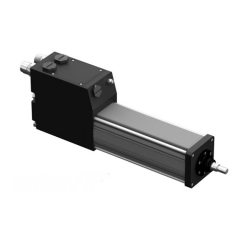
The Exlar Tritex Series of electric actuators combines an integrated brushless servo motor,
amplifier and motion controller. Optionally the system can be configured for remote mounting of
the amplifier and motion control
Integrated actuator, servo motor, amplifier and motion control
Integrated actuator and servo motor with remote drive amplifier and motion control
I/O
8 inputs
4 outputs
1 analog input
(0-10v or 4-20ma)
1 analog output
(0- 20 ma)
RS 485
Communication
port
24 – 48V
DC power
supply
TRA
-
500
TSM, RSM or RSG
24 – 48V
DC power
supply
I/O
8 inputs
4 outputs
1 analog input
(0-10v or 4-20ma)
1 analog output
(0- 20 ma)
RS 485
Communication
port

Tritex 1 Installation and Setup 10 09/27/12
PN: 27666 Exlar Corporation
Rev. M 952-500-6200M
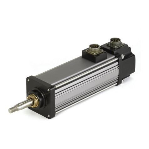
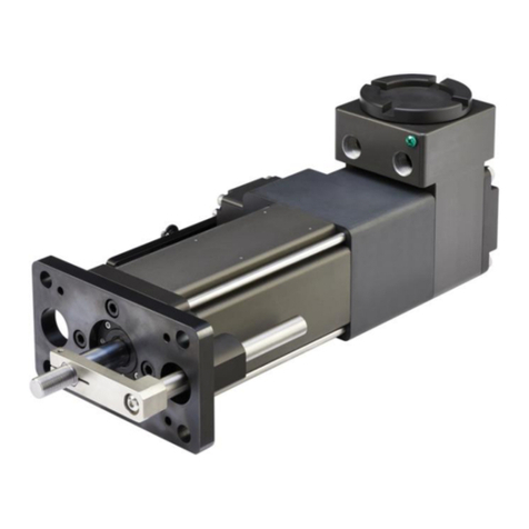
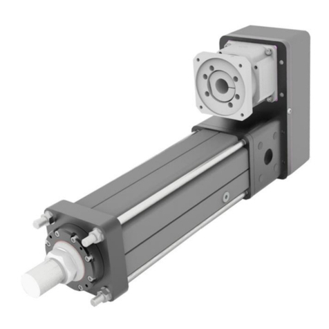
The Tritex actuators are available in linear and rotary versions with integrated or remote
amplifier and motion control. The Remote amplifier and motion control models would typically
be used in application where space at the actuator is limited or in applications with high ambient
temperatures.
Actuator
Models
N
umbers
With Integrated amplifier
& motion control
Remote mount amplifier
and motion control
TRA500-x
Size and type
TLM20-(see model mask) TSM-20-(see model mask) 2 inch linear actuator
TLM30-(see model mask) TSM-30-(see model mask) 3 inch linear actuator
RTM60-(see model mask) RSM-60-(see model mask) 60 mm motor
RTG60-(see model mask) RSG-60-(see model mask) 60 mm gear motor
RTM90-(see model mask) RSM-90-(see model mask) 90 mm motor
RTG90-(see model mask) RSG-90-(see model mask) 90 mm gear motor
All of the required power components and motion processor are contained in the actuator or
remote housing.
Input 8
Input 7
Input 6
Input 5
Input 4
Input 3
Input 2
Input 1
Output 4
Output 3
Output 2
Output 1
RS-485
Logic
Power
BUS +
BUS -
BUS Power
Common
Logic Power
GND
24 – 48 V
Power Supply
Analog Input
Analog Output
24V I/O
Supply

Tritex 1 Installation and Setup 11 09/27/12
PN: 27666 Exlar Corporation
Rev. M 952-500-6200M
General Specifications
Drive Specification for all Tritex Models with embedded drives
Embedded
Drive Specifications
Input Voltage, Bus
and Logic 24-48 Volts DC nominal, 20 -60 Volts continuous operating range.
Under voltage trip 19V, Over voltage trip 85V
I/O Power Supply
24V nominal, 30V max, 12V min
Digital Inputs
8 – opto- isolated, 24V nominal 30V max, programmable functions
Digital Outputs
4 – opto- isolated 50 mA continuous, short circuit protected,
programmable functions
Analog Input
0-10 Volts or 0-20 mA, differential input 12 bit resolution, programmable
as position, velocity or torque command
Analog Output
0-20 mA, 11 bit resolution, programmable functions
Serial Interface
RS-485, Modbus RTU protocol, max baud rate 38.4k
Commutation
Sinusoidal, 15kHz PWM
Resolution
0.001 revolution
Accuracy
+ / - 0.005 revolution
Output Current
Continuous and peak output current is dependent on actuator
Environmental
Ambient Temperature for rated output: 25° C
Maximum Operating temperature range 0° – 55° C
Power De-rating of 2.5% per degree C between 25° C and 55° C
Humidity: 10 to 95% non-condensing
EMC
IEC/EN 61800-3:2004-08 with use of shielded cables and EFT/B &
Surge Filter 37263 (see Accessories section) or similar
Drive specifications for TRA500 remote option
TRA500 Remote
Drive Specifications
Input Voltage, Bus
and Logic 24-48 Volts DC nominal, 20 -60 Volts continuous operating range.
Under voltage trip 19V, Over voltage trip 85V
I/O Power Supply
24V nominal, 30V max, 12V min
Digital Inputs
8 – opto- isolated, 24V nominal 30V max, programmable functions
Digital Outputs
4 – opto- isolated 50 mA continuous, 24V nominal 30V max, short
circuit protected, programmable functions
Analog Input
0-10 Volts or 0-20 mA, differential input 12 bit resolution, programmable
as position, velocity or torque command
Analog Output
0-20 mA, 11 bit resolution, programmable functions
Serial Interface
RS-485, Modbus RTU protocol, max baud rate 38.4k
Commutation
Sinusoidal, 15kHz PWM
Feedback
Analog Hall
Continuous Output
Current (Peak of sine
Amps)*
25° C Ambient 40° C Ambient 55° C Ambient
Stall Rated Stall Rated Stall Rated
15 15 14 12 12 8.5
Peak Output Current
(Peak of sine Amps) 20
Environmental
IP65, Humidity: 10 to 95%, non-condensing
*Actual output current may be reduced if the motor/actuator continuous and peak current ratings
are lower

Tritex 1 Installation and Setup 12 09/27/12
PN: 27666 Exlar Corporation
Rev. M 952-500-6200M
Specifications: Size 20 Linear Actuators
TLM20
TLM series includes embedded drive and motion controller.
TLM 20 LINEAR ACTUATOR PERFORMANCE SPECIFICATIONS
Backlash in (mm) .008 (.20)
Lead Accuracy in/ft (mm/300 mm) .001 (.025)
Maximum Radial Load lb (N) 15 (67)
Environmental Rating IP54
Stator 1 Stack 1B8-50 2 Stack 2B8-34 3 Stack 3B8-25
Lead RPM at 48 VDC* 5000 3400 2500
0.1 Stall Force lbf (N) 239 (1063) 377 (1677) 503 (2237)
Max Speed in/sec (mm/sec) 8.33 (212) 5.66 (144) 4.17 (2237)
0.2 Stall Force lbf (N) 119 (529) 188 (836) 251 (1117)
Max Speed in/sec (mm/sec) 16.66 (424) 11.33 (288) 8.33 (212)
0.4 Stall Force lbf (N) 60 (267) 94 (418) 126 (560)
Max Speed in/sec (mm/sec) 33.33 (848) 22.66 (575) 16.66 (424)
Power Supply Current
Draw at Rated Power
(48V) Amps 10 10 10
Resolution 0.001 revolutions x lead
Accuracy (not including
backlash) +/- 0.005 revolutions x lead
Stroke Length in (mm) 3 (75) 6 (150) 10 (254) 12 (300)
Approximate Weight lb
(kg) 7 (3.2) 8.5 (3.9) 10 (4.5) 11.5 (5.2)

Tritex 1 Installation and Setup 13 09/27/12
PN: 27666 Exlar Corporation
Rev. M 952-500-6200M
TSM20
TSM series requires a TRA500 remote drive and motion controller.
TSM 20 LINEAR ACTUATOR PERFORMANCE SPECIFICATIONS
Backlash in (mm) .008 (.20)
Lead Accuracy in/ft (mm/300
mm) .001 (.025)
Maximum Radial Load lb (N) 15 (67)
Environmental Rating IP54
Stator 1 Stack 1B8-50 2 Stack 2B8-34 3 Stack 3B8-25
RPM at 48
VDC 5000 3400 2500
Lead
Ambient
Temp Deg C 25° 40° 55° 25° 40° 55° 25° 40° 55°
0.1
Stall Force lbf
(N) 295
(1312) 262
(1165) 227
(1010) 460
(2046) 411
(1828) 355
(1579) 575
(2558) 514
(2286) 445
(1979)
Max Speed in/sec
(mm/sec) 8.33 (212) 5.66 (144) 4.17 (106)
0.2
Stall Force lbf
(N) 148
(658) 131
(583) 113
(503) 230
(1023) 205
(912) 177
(787) 288
(1281) 257
(1143) 223
(992)
Max Speed in/sec
(mm/sec) 16.66(424) 11.33(288) 8.33(212)
0.4
Stall Force lbf
(N) 74
(329) 66
(294) 57
(254) 92
(409) 82
(365) 71
(316) 115
(512) 103
(458) 89
(396)
Max Speed in/sec
(mm/sec) 33.33 (848) 22.66 (575) 16.66 (424)
Power Supply Current
Draw at Rated Power
(48V) Amps
10
10
10
Resolution 0.001 revolutions x lead
Accuracy (not including
backlash) +/- 0.005 revolutions x lead
Stroke Length in
(mm)
3
(75)
6
(150)
10
(254)
12
(300)
Approximate Weight lb
(kg) 6.5 (2.9) 7.0 (3.2) 7.5 (3.4) 8.0 (3.6)

Tritex 1 Installation and Setup 14 09/27/12
PN: 27666 Exlar Corporation
Rev. M 952-500-6200M
Specifications: Size 30 Linear Actuators
TLM30
TLM series includes embedded drive and motion controller.
TLM 30 LINEAR ACTUATOR PERFORMANCE SPECIFICATIONS
Backlash in (mm) .008 (.20)
Lead Accuracy in/ft (mm/300 mm) .001 (.025)
Maximum Radial Load lb (N) 15 (67)
Environmental Rating IP54
Stator 1 Stack 1B8-20 2 Stack 2B8-13 3 Stack 3B8-10
Lead RPM at 48 VDC* 2000 1300 1000
0.1 Stall Force lbf (N) 585 (2606) 935 (4159) 1250 (5560)
Max Speed in/sec (mm/sec) 3.33 (84.6) 2.17 (55.1) 1.67 (42.4)
0.2 Stall Force lbf (N) 293 (1303) 468 (2082) 625 (2780)
Max Speed in/sec (mm/sec) 6.67 (169.4) 4.33 (109.9) 3.33 (84.6)
0.5 Stall Force lbf (N) 117 (520) 187 (832) 250 (1112)
Max Speed in/sec (mm/sec) 16.67 (423.4) 10.83 (275.1) 8.33 (211.6)
Power Supply Current Draw
at Rated Power (48V) Amps 10
10
10
Resolution 0.001 revolutions x lead
Accuracy (not including
backlash) +/- 0.005 revolutions x lead
Stroke Length in (mm) 3 (75) 6 (150) 10 (254) 12 (300) 18 (450)
Approximate Weight lb (kg) 10 (4.5) 12 (5.4) 19.5 (8.8) 21 (9.5) 25.5 (11.6)

Tritex 1 Installation and Setup 15 09/27/12
PN: 27666 Exlar Corporation
Rev. M 952-500-6200M
TSM30
TSM series requires a TRA500 remote drive and motion controller.
TSM 30 LINEAR ACTUATOR PERFORMANCE SPECIFICATIONS
Backlash in (mm) .008 (.20)
Lead Accuracy in/ft
(mm/300 mm) .001 (.025)
Maximum Radial Load lb (N) 15 (67)
Environmental Rating IP54
Stator 1 Stack 1B8-20 2 Stack 2B8-13 3 Stack 3B8-10
RPM at 48 VDC* 2000 1300 1000
Lead Amb. Temp Deg C 25° 40° 55° 25° 40° 55° 25° 40° 55°
0.1 Stall Force lbf
(N) 756
(3362) 686
(3051) 608
(2704) 1201
(5342) 1091
(4853) 968
(4306) 1545
(6872) 1404
(6245) 1247
(5547)
Max Speed in/sec (mm/sec) 3.33 (84.6) 2.17 (55.1) 1.67 (42.4)
0.2 Stall Force lbf
(N) 378
(1681) 343
(1526) 304
(1352) 600
(2669) 545
(2425) 484
(2153) 772
(3434) 702
(3123) 623
(2771)
Max Speed in/sec (mm/sec) 6.67 (169.4) 4.33 (109.9) 3.33 (84.6)
0.5 Stall Force lbf
(N) 151
(672) 137
(609) 122
(543) 240
(1068) 218
(970) 194
(862) 309
(1375) 281
(1250) 249
(1108)
Max Speed in/sec (mm/sec) 16.67 (423.4) 10.83 (275.1) 8.33 (211.6)
Power Sup
ply Current
at Rated Power (48V) Amps 15
12
10
15
12
10
15
12
10
Resolution 0.001 revolutions x lead
Accuracy (not
including backlash) +/- 0.005 revolutions x lead
Stroke Length in
(mm)
3
(75)
6
(150)
10
(254)
12
(300)
18 (450)
Approximate Weight lb
(kg) 9.5 (4.3) 11.5 (5.2) 19 (8.6) 22 (10) 25 (11.3)

Tritex 1 Installation and Setup 16 09/27/12
PN: 27666 Exlar Corporation
Rev. M 952-500-6200M
Specifications: Size 60 Motors and Gear motors
RTM060
RTM060 series includes embedded drive and motion controller.
RTM060 ROTARY MOTOR TORQUE AND SPEED RATINGS
For output torque of RTG Gearmotors, multiply by ratio and efficiency. Please note maximum allowable
output torques in the Gearmotor Mechanical Ratings table page 16.
Stator 1 Stack 1B8-50 2 Stack 2B8-34 3 Stack 3B8-25
RPM at 48 VDC 5000 3400 2500
Cont. Stall Torque lbf-in (Nm) 4.7 (.53) 7.5 (.85) 10 (1.13)
Peak Torque lbf-in (Nm) 9.4 (1.06) 15 (1.69) 20 (2.26)
Power Supply
Current Draw at
Rated Power (48V) Amps
10
10
10
Resolution 0.001 revolutions / ratio
Accuracy (not
including backlash)
+/- 0.005 revolution / ratio
RSM060 and RSG060
RSM& RSG060 series requires a TRA500 remote drive and motion controller
RSM060 ROTARY MOTOR TORQUE AND SPEED RATINGS
For output torque of RSG gearmotors, multiply by ratio and efficiency. Please note maximum allowable output
torques in the Gearmotor Mechanical Ratings table page 16.
Stator 1 Stack 1B8-50 2 Stack 2B8-34 3 Stack 3B8-25
RPM at 48
VDC 5000 3400 2500
Ambient Temp Deg C 25° 40° 55° 25° 40° 55° 25° 40° 55°
Cont. Stall Torque lbf-in
(Nm) 5.9
(.53) 5.2
(.53)
4.5
(.53)
9.2
(.85) 8.2
(.53)
7.1
(.53)
11.4
(1.13) 10.2
(.53)
8.9
(.53)
Peak Torque lbf-in (Nm) 9.4 (1.06) 15 (1.69)
20 (2.26)
Power Supply
Current Draw at
Rated Power (48V) Amps
10
10
10
Resolution 0.001 revolutions / ratio
Accuracy (not
including backlash)
+/- 0.005 revolution / ratio
RTM/RTG and RSM/RSG060 INERTIA
Stator 1 Stack 2 Stack 3 Stack
Motor Armature Inertia (+/-5%) lb-in-sec2 (kg-cm2)0.000237 (0.268) 0.000413 (0.466) 0.000589 (0.665)
Gearmotor Armature Inertia* lb-in-sec2 (kg-cm2)0.000226 (0.255) 0.000401 (0.453) 0.000576 (0.651)
*Add armature inertia to gearing inertia for total inertia.

Tritex 1 Installation and Setup 17 09/27/12
PN: 27666 Exlar Corporation
Rev. M 952-500-6200M
S
IZE 6
0 RADIAL LOAD
AND BEARING LIFE
S
IZE 6
0
GEARMOTOR MECHANICAL RATINGS
S
IZE 6
0
BACKLASH AND EFFICIENCY
SIZE 60 GEARING REFLECTED INERTIA
Single Reduction Double Reduction
Gear Stages Lbf-in-sec
2
(kg-cm
2
) Gear Stages Lbf-in-sec
2
(kg-cm
2
)
4:1 0.0000132 (0.0149) 16:1 0.0000121 (0.0137)
5:1 0.0000087 (0.00984) 20:1, 25:1 0.0000080 (0.00906)
10:1 0.0000023 (0.00261) 40:1, 50:1, 100:1 0.0000021 (0.00242)

Tritex 1 Installation and Setup 18 09/27/12
PN: 27666 Exlar Corporation
Rev. M 952-500-6200M
Specifications: Size 90 motors and Gear Motors
RTM090
RTM090 series includes embedded drive and motion controller
RTM090 ROTARY MOTOR TORQUE AND SPEED RATINGS
For output torque of RTG Gearmotors, multiply by ratio and efficiency. Please note maximum allowable
output torques in the Gearmotor Mechanical Ratings page 18.
Stator 1 Stack 1B8-17 2 Stack 2B8-10 3 Stack 3B8-07
RPM at 48 VDC 1700 1000 700
Cont. Stall Torque lbf-in (Nm) 19 (2.1) 29 (3.3) 45 (5.0)
Peak Torque lbf-in (Nm) 30 (3.4) 50 (5.6) 70 (7.9)
Power Supply
Current Draw at
Rated Power (48V) Amps
10
10
10
Resolution 0.001 revolutions / ratio
Accuracy (not
including backlash)
+/- 0.005 revolution / ratio
RSM090 and RSG090
RSM& RSG090 series requires a TRA500 remote drive and motion controller
RSM090 ROTARY MOTOR TORQUE AND SPEED RATINGS
For output torque of RSG gearmotors, multiply by ratio and efficiency. Please note maximum allowable
output torques in the Gearmotor Mechanical Ratings able page 18.
Stator 1 Stack 1B8-17 2 Stack 2B8-10 3 Stack 3B8-07
RPM at
48 VDC 1700 1000 700
Ambient Temp Deg C 25° 40° 55° 25° 40° 55° 25° 40° 55°
Cont. Stall Torque lbf-in
(Nm) 22
(2.5) 20
(2.3)
17.5
(2.0)
37
(4.2) 34
(3.8)
30
(3.4)
51
(5.7) 46
(5.2)
42
(4.7)
Peak Torque lbf-in
(Nm) 30 (3.4) 15 (5.6)
70 (7.9)
Power Supply
Current Draw at
Rated Power (48V) Amps
15 12 10 15 12 10 15 12 10
Resolution 0.001 revolutions / ratio
Accuracy (not
including
backlash)
+/- 0.005 revolution / ratio
RTM/RTG and RSM/RSG090 INERTIA
Stator 1 Stack 2 Stack 3 Stack
Motor Armature Inertia (+/-5%) lb-in-sec2 (kg-cm2)0.00054 (0.609) 0.00097 (1.09) 0.00140 (1.58)
Gearmotor Armature Inertia* lb-in-sec2 (kg-cm2)0.00114 (1.29) 0.00157 (1.77) 0.00200 (2.26)
*Add armature inertia to gearing inertia for total inertia.

Tritex 1 Installation and Setup 19 09/27/12
PN: 27666 Exlar Corporation
Rev. M 952-500-6200M
S
IZE
90 RADIAL LOAD AND BEARING LIFE
S
IZE
90
GEARING REFLECTED INERTIA
S
IZE
90
BACKLASH AND EFFICIENCY
S
IZE
90
MECHANICAL RATINGS

Tritex 1 Installation and Setup 20 09/27/12
PN: 27666 Exlar Corporation
Rev. M 952-500-6200M
Model Mask and Ordering Information
TLM Series TRITEX TLM SERIES ORDERING GUIDE
AAABB-CCDD-EFG-HHH-HH - (XX…XX - #####)
AAA = Actuator Type G = Rod End
TLM = Tritex Linear Actuator M = Male US Std Thread A = Male Metric
BB = Actuator Frame Size F = Female US Std Thread B = Female Metric
20 = 2 inch nominal frame actuator X = Special (please specify)
30 = 3 inch nominal frame actuator HHH-HH - Motor Stator
CC = Stroke Length TLM20
03 = 3 inch (75 mm) 1B8-50 = 1 Stack, 5000 rpm at 48 VDC, 2500rpm at 24
VDC
06 = 6 inch (150 mm) 2B8-34 = 2 Stack, 3400 rpm at 48 VDC, 1700 rpm at 24
VDC
10 = 10 inch (254 mm) 3B8-25 = 3 Stack, 2500 rpm at 48 VDC, 1250 rpm at 24
VDC
12 = 12 inch (305 mm) TLM30
18 = 18 inch (457 mm) (TLM30 only) 1B8-20 = 1 Stack, 2000 rpm at 48 VDC, 1000 rpm at 24
VDC
DD = Lead (linear motion per screw revolution) 2B8-13 = 2 Stack, 1300 rpm at 48 VDC, 750 rpm at 24
VDC
01 = 0.1 inch (2.54 mm) 3B8-10 = 3 Stack, 1000 rpm at 48 VDC, 500 rpm at 24
VDC (not available in 3 inch stroke)02 = 0.2 inch (5.08 mm)
04 = 0.4 inch (10.16 mm) (TLM20 only)
XX..XX = Travel and Housing Options (Multiples
Possible)
05 = 0.5 inch (12.7 mm) (TLM30 only) Travel Options
E = Connections AR = External Anti-rotate L1/2/3 = External Limit
Switches
I = Exlar std M23 style connector PF = Preloaded Follower* RB = Rear Brake
(future option)
Bxx = Embedded leads, 3 ft. XT = Special Travel Options
Pxx = Embedded leads w/plug, std M23 style connector,
3 ft. Housing Options
X = Special (please specify) P5 = IP65 sealed housing
F = Mounting Special Motor Options
C = Rear Clevis D = Double Side Mount XL = Special Lubrication
E = Extended Tie Rod F - Front Flange XM = Special Motor Option
S = Side Mount T = Side Trunnion
##### = 5 digit PN assigned to designate special
model
number
M = Metric Extended Tie Rod X = Special Optional 5 digit assigned PN to designate unique model
numbers
* The dynamic load rating of zero backlash, preloaded screws is 63% of the dynamic load rating of the std non-
preloaded screws. The calculated travel life of a preloaded screw will be 25% of the calculated travel life of the same
size and lead of a non-preloaded screw.
Table of contents
Other Exlar Controllers manuals
Popular Controllers manuals by other brands
Titan Controls
Titan Controls SPARTAN Series instruction manual
Soyal
Soyal AR727HV3 quick guide

Telecom Behnke
Telecom Behnke BEHNKE-STATION Technical manual
Phoenix Contact
Phoenix Contact ILC 130 ETH user manual

Matsunaga
Matsunaga TSA-1030-CJ operating instructions
Vortice
Vortice Vort Delta T WIFI Instruction booklet

IMC
IMC EAGLE 2 SOLR-2ELC-10 Service and parts manual supplement
LIXiSE
LIXiSE LXC701 Series user manual
Honeywell
Honeywell CentraLine LYNX BACnet CLLYUB1012S Product data
WAREMA
WAREMA BACnet 4M230.8I AP installation instructions

Sinovo
Sinovo SD300-2S-0.7G user manual

Pacific Power Source
Pacific Power Source UPC-3 Operation manual
