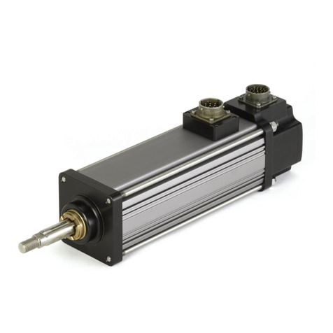
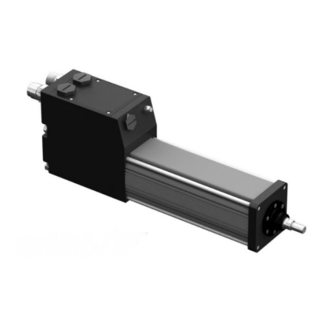
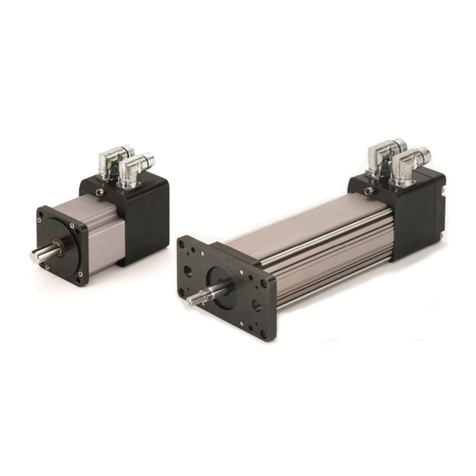
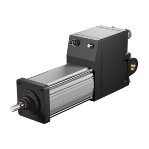
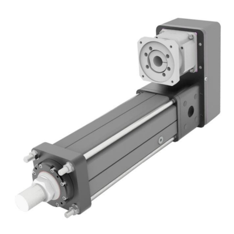
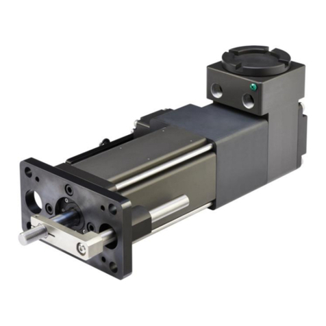
Exlar Curtiss-Wright Tritex TTX Series Installation and maintenance instructions

Information furnished by Exlar Corporation is believed to be accurate and reliable. However, no responsibility is assumed by Exlar Corporation for
its use. Exlar reserves the right to change the design and operation of the equipment described herein and any associated motion products that
may appear in this document. Information in this document pertaining to equipment not furnished by Exlar should be conrmed by that equipment
manufacturer. Exlar assumes no responsibility for changes to information by other manufacturers or errors in that information or the description of that
information. Information in this document is subject to change without notice.
This document does not contain any export-controlled technical data.
Installation & Service Instructions
Rev. D | PN75667 | 8/1/22
Tritex®TTX SERIES actuators
Tritex® TTX Vdc Models

2| Tritex® TTX Series DC Actuator Installation & Maintenance Instructions Curtiss-Wright | Rev D | PN75667 | 8/1/22
CONTENTS
1.0 INTRODUCTION ............................................................... 3
1.1 General Product Description......................................... 3
1.2 Product Features........................................................... 3
1.3 Safety Considerations................................................... 5
2.0 SYSTEM CONFIGURATION ............................................ 6
2.1 Tritex TTX Series Actuator............................................ 6
2.2 Options ......................................................................... 6
2.2.1 Internal Holding Brake.......................................... 6
2.2.2 Anti-Rotation Assembly......................................... 6
2.2.3 External Limit Switch ............................................ 6
3.0 MECHANICAL INSTALLATION ........................................ 6
3.1 Mounting Congurations............................................... 6
3.2 Mounting Considerations .............................................. 8
3.2.1 General Operation...................................................... 8
3.2.2 Actuator Alignment ............................................... 8
3.2.3 Anti-Rotation Assembly ........................................ 9
3.2.4 External Limit Switches.......................................10
3.3 Lubrication................................................................... 11
3.4 Outdoor and Wash Down Installations........................ 11
4.0 ELECTRICAL INSTALLATION........................................ 12
4.1 Introduction ................................................................. 12
4.2 Supplied Connectors .................................................. 14
4.3 Grounding (PE) Connection........................................ 14
4.3.1 Shielding............................................................. 14
4.3.2 Other Grounding Considerations........................ 15
4.4 DC Input Power........................................................... 15
4.4.1 Input Power Ratings ........................................... 15
4.5 Over Temperature Protection...................................... 15
4.6 I/O Power Supply........................................................ 15
4.6.1 I/O Connector Wiring.......................................... 16
4.7 Digital Inputs............................................................... 18
4.8 Digital Outputs ............................................................ 18
4.9 Actuator Brake Option................................................. 19
4.10 Analog Input.............................................................. 19
4.11 Analog Output ........................................................... 20
4.12 Communications....................................................... 20
4.13 IA4 Option Board Connections ................................. 21
4.14 4-20 mA Input ........................................................... 22
4.14.1 4-20 mA Input Connection................................ 22
4.15 4-20 mA Output......................................................... 22
4.16 Absolute Feedback ................................................... 23
4.17 Battery Life Information............................................. 23
4.17.1 Low Battery Voltage.......................................... 23
4.17.2 Replacing the Battery ....................................... 24
4.18 Ethernet Options, EIP, TCP or PIO........................... 24
4.19 Shielded or Unshielded Cables ................................ 24
5.0 MAIN POWER SUPPLY SELECTION............................... 25
5.1 Unregulated AC/DC Power Supplies .......................... 25
5.2 Regulated AC/DC Power Supplies ............................. 25
5.3 Power and Battery Systems ....................................... 26
5.4 Handling Regen Energy-Internal Shunt...................... 26
5.5 Handling Regen Energy-External Shunt..................... 27
5.6 Logic Power Supply.................................................... 27
5.7 Power Supply Wiring Diagrams.................................. 27
5.8 Grounding................................................................... 28
5.9 Power Supply Connections......................................... 28
6.0 STARTUP .......................................................................... 29
6.1 Considerations for Startup.......................................... 29
6.1.1 Safety Considerations ........................................ 29
6.1.2 Rotary-to-Linear Motion Relationship................. 29
6.2 General Startup Procedure......................................... 29
7.0 MAINTENANCE PROCEDURES...................................... 30
7.1 Lubrication .................................................................. 30
7.2 Seal Maintenance....................................................... 31
7.3 Replacement Faceplate Assembly Kit ........................ 31
8.0 TROUBLESHOOTING PROCEDURE .............................. 32
9.0 CABLE ACCESSORIES.................................................... 33
9.1 TTIOC-xxx I/O Cable .................................................. 33
9.2 CBL-TTIPC-SMI-xxx Power Cable ............................. 33
9.3 TTICO-xxx Communications Cable ............................ 34
10.0 PRODUCT RETURNS .................................................... 35
11.0 CERTIFICATIONS ........................................................... 35
12.0 WARRANTY AND LIMITATION OF LIABILITY................ 36

TTX Series DC Actuator Installation & Maintenance Instructions | 3www.exlar.com | 952.500.6200
1.0 INTRODUCTION
1.1 GENERAL PRODUCT DESCRIPTION
The Tritex TTX Series is Exlar’s latest family of fully integrated
linear actuators. They feature a robust planetary roller screw
mechanism integrated into the rotor of a brushless servomotor
and drive. This unique design combines the high speed and
high load capacity of the roller screw with the high torque-to-
volume ratio of the brushless servomotor. This manual applies
only to the Tritex TTX DC actuators. Other manuals will cover
Tritex TTX AC actuators. All the required power components
and the motion processor are contained in the actuator housing.
Commissioning software and set-up uses the Exlar Expert™
software tools used on all Tritex II integrated actuators
Actuator Mechanical Specications and Ratings
Please refer to the Tritex TTX Standard Product Catalog for
mechanical specications and output force ratings. The catalog
also contains available model options and ordering information
for specic model selection.
Tritex TTX Series actuators feature an Ingress Protection
Rating of IP66S.
1.2 PRODUCT FEATURES
Figure 1 – Tritex TTX060 Series Actuator features
Motor & Roller
Screw Housing
RS485 Port: Modbus RTU
Conguration or Command
Ethernet Port:
EtherNet/IP
PROFINET
Modbus TCP
Actuator Main Rod
Power Connector:
Main and Control Power,
GND (PE)
Electronics Housing
Figure 1 – Tritex TTX080 Series Actuator features
Electronics Housing
Actuator Main Rod
Motor & Roller
Screw Housing
Ethernet Port:
EtherNet/IP
PROFINET
Modbus TCP
RS485 Port: Modbus RTU
Conguration or Command
Power Connector:
Main and Control Power,
GND (PE)

4| Tritex® TTX Series DC Actuator Installation & Maintenance Instructions Curtiss-Wright | Rev D | PN75667 | 8/1/22
DRIVE SPECIFICATIONS FOR ALL TRITEX TTX DC MODELS
Drive Specications
Main Power Input Voltage
Control and Power Input
Voltage (Optional)
Nominal Input Voltage: 12 to 48 Vdc
Tolerance: ±10% of nominal
Note: Control Power is optional.
Optional External I/O
Power Supply
(Required with brake)
24 Vdc ±10% - 0.8 A dc max load
Provides power for Digital Outputs when powering brake and 12 to 30 V when no brake is used
Requires Class 2 source, or protected by 3 A maximum fuse
Digital Inputs 10 to 30 Vdc for ON state
0 to 1 Vdc or 0 to 1mA for OFF state
Common return at “I/O Common” terminal
Programmable functions.
Number of channels varies by I/O option: 4 for 4-20 mA and 8 for all others
Digital Outputs Powered at I/O +24 V terminal
1 V maximum drop from supply voltage
100 mA continuous load per channel
Short circuit and overload protected
Programmable functions
Number of channels varies by I/O option: 3 for 4-20 mA and 4 for all others
Analog Input
(Not available on 4-20 mA
I/O option)
0-10 V or ±10 V dierential input
13-bit resolution, ±0.2% accuracy.
Programmable function – Position, Velocity, or Torque
Analog Output
(Not available on 4-20 mA
option)
0-10 V at up to 10 mA
11-bit resolution; ±0.5% accuracy
Programmable function
4-20 mA Analog Input
(4-20 mA I/O option only)
Externally powered, fully isolated
11.5 V max lift-o at 20 mA
14-bit resolution, ±0.1% of span accuracy
Programmable function – Position, Velocity, or Torque
4-20 mA Analog Output
(4-20 mA I/O option only)
Externally powered, fully isolated
12 V max lift-o at 20 mA
12-bit resolution, ±0.2% accuracy
Serial Interface Optically isolated RS485, Modbus RTU protocol
Selectable bit rate: 38.4 kbaud max
Commutation Sinusoidal, 10kHz pw, space vector voltage
Position Feedback Resolution: 0.001 revolution
Accuracy: ±0.002 revolution
Multi-turn absolute position is standard, but may be disabled and battery back-up removed
Enclosure Rating IP66S with plugs, caps, and cover properly installed and connectors or wiring ports properly sealed
Environmental Operating temperature range: 0 °C to 65 °C
Derate continuous current 1% per 1 °C above 25 °C
Storage Temperature: -40 °C to 85 °C
Operational Altitude: up to 3000 m
Long-term vibration: 1 grms 5 to 500 Hz
Occasional vibration: 2.5 grms 5 to 500 Hz. Shock: 5g peak

TTX Series DC Actuator Installation & Maintenance Instructions | 5www.exlar.com | 952.500.6200
1.3 SAFETY CONSIDERATIONS
Safety is of paramount importance during the installation and
operation of your Tritex TTX Series actuator. Throughout this
manual, content agged with the cautionary symbols shown
below should be read carefully by installers and operators to
help avoid property damage, personal injury or death.
WARNING! Indicates a potentially hazardous situation
which could result in serious injury or death if precautions are
not
CAUTION! Indicates the information following is
necessary for avoiding a risk of damage to the product or other
equipment.
IMPORTANT Identies statements that provide important
information to help ensure safe and trouble-free installation and
operation.
Several general warnings and cautions follow. In addition, refer
to the AGENCY APPROVALS section for Conditions of Use for
additional limits and requirements to ensure safe installation
and operation.
WARNING! General
Failure to follow safe installation guidelines can cause death
or serious injury. Voltages and currents in the product can
cause electric shock or burns and could be lethal. Extreme
care is necessary at all times when working with or adjacent
to the product. The installation must comply with all relevant
safety legislation in the country of use. The forces created by
the actuator could be lethal or cause severe injury if proper
protection is not provided to keep personnel away from moving
components.
WARNING! System Design and safety for personnel
The actuator is intended as a component for professional
incorporation into complete equipment or a system. If installed
incorrectly, the actuator may present a safety hazard. The
actuator uses high voltages and currents, carries a high level of
stored electrical energy, and is used to control equipment which
can cause injury. Close attention is required to the electrical
installation and the system design to avoid hazards either in
normal operation or in the event of equipment malfunction.
System design, installation, commissioning, and maintenance
must be carried out by personnel who have the necessary
training and experience. They must read this safety information
and this manual carefully.
None of the functions or features of the Tritex TTX actuator may
be used to ensure safety of personnel. They must not be used
for safety-related functions.
For example, the actuators enable / disable, brake, stop/
start and forward/reverse functions are not sucient for use
in safety-critical applications without additional independent
channels of protection. Careful consideration must be given to
the functions of the actuator, which might result in a hazard,
either through their intended behavior or through incorrect
operation due to a fault. In any application where a malfunction
of the actuator or its control system could lead to or allow
damage, loss or injury, a risk analysis must be carried out, and
where necessary, further measures taken to reduce the risk- for
example a fail-safe brake in case of loss of actuator braking
power.
WARNING! Hot Surface – Risk of Burn
Exposed surfaces of the actuator may exceed 70 °C under
normal operation and can take a long time to cool, resulting in a
risk of burns when touched.

6| Tritex® TTX Series DC Actuator Installation & Maintenance Instructions Curtiss-Wright | Rev D | PN75667 | 8/1/22
1.4 LABEL INFORMATION
Actuator Type
TTX = Integrated Drive / Motor / Actuator
AAA = Actuator Frame Size
080 = 80 mm (3.15 in)
060 = 60 mm (2.36 in)
BBB = Stroke Length
100 = 100 mm
150 = 150 mm
300 = 300 mm
450 = 450 mm
CC =Screw Lead
01 = 0.10 in (2.54 mm)
02 = 0.20 in (5.08 mm)
05 = 0.50 in (12.7 mm)
D = Winding Voltage
4 = 230 Vac Max
D = 48 Vdc Max
E = Rod End Thread
A = Male Metric
B = Female Metric2
M = Male, English)2
F = Female, English2
F = Internal Holding Brake
N = No Brake
B = Internal Holding Brake, Electrically Released
G = Amplier Voltage
A = 200 Vac Class
D = 48 Vdc Class
HHH = Option Boards
SIO = Standard I/O Interconnect
IA4 = 4-20 mA Analog I/O
EIP = SIO plus EtherNet/IP w/M12 connector
PIO = SIO plus PROFINET IO w/M12 connector
TCP = SIO plus Modbus TCP w/M12 connector
M = Mounting Options
N = None
1 = Front Flange, Metric
3 = Tapped Face, Metric
5 = Rear Clevis, Metric
F = Front Flange, English2
C = Rear Clevis, English2
N = Accessory Options
N = None
A = Anti-Rotate Assembly
L = Limit Switch Housing / Anti-Rotate Assembly1
1Switches sold separately
2 Available option. May add lead time.
Sample Product Number: TTX080-0300-02-D-B-B-D-PIO-1-A
Option Boards
Stroke Length
BBB DG
Winding Voltage
Actuator Type & Frame Size
TTX AAA
Rod End Thread
Screw Lead
CC E FM
Mounting Options
N
Other Options
Internal Holding Brake Amplifier Voltage
HHH

TTX Series DC Actuator Installation & Maintenance Instructions | 7www.exlar.com | 952.500.6200
2.0 SYSTEM CONFIGURATION
2.1 TRITEX TTX SERIES ACTUATOR
Tritex TTX Series actuators provide a robust solution for long-
life, continuous-duty applications even when environmental
contaminants are an issue. In most rotary-to-linear devices,
critical mechanisms are exposed to the environment and must
be frequently inspected, cleaned and lubricated. In contrast,
Tritex TTX Series actuators are designed with all converting
components mounted within sealed motor housings. With a
simple bushing and seal on the smooth extending rod, abrasive
particles or other contaminants are prevented from reaching
the actuator’s critical mechanisms. As a result, actuator life
can exceed that of a ball screw actuator by 15 times, even in
high-speed, high-force applications. In addition, the Tritex TTX
Series has an on-board amplier with control software and
rmware available from Exlar.
2.2 OPTIONS
2.2.1 Internal Holding Brake
Many applications require the addition of a holding brake. The
Exlar internal holding brake is engaged by a permanent magnet.
The mechanical advantage of the roller screw allows the holding
brake to prevent the output rod from back driving the load. The
holding capacity of the brake is sucient to hold the rated force
of the actuator.
2.2.2 Anti-Rotation Assembly
The unique design of Tritex TTX Series actuators helps simplify
actuator setup by allowing the user to rotate the extending
rod and thread it in and out of the actuator for mechanical
attachment or system testing. In most applications, the load
is coupled to linear bearings or some other support device,
preventing rotation during operation. To ensure proper linear
motion in applications in which the rod is free to rotate, an Anti-
Rotate Assembly is required to prevent the rod from rotating.
2.2.3 External Limit Switch
A Tritex TTX Series actuator equipped with the anti-rotate and
limit switch options can accommodate multiple limit switches
for use as end-of-travel limit switches or home position sensors
positioned outside the low-prole extruded channel housing.
3.0 MECHANICAL INSTALLATION
3.1 MOUNTING CONFIGURATIONS
Figure 2 – Mounting congurations
Tritex TTX Series actuators mounting congurations:
• Rear clevis
• Front ange
• Tapped face
• Side mount.
TTX060: 5 mm Hex
TTX080: 6 mm Hex
Torque: 4.6 Nm (3.4 ft-lbs)
Torque: 12.2 Nm (9 ft-lbs)
Figure 3 – Rear clevis mount (NOTE: Dimension drawings can be
found in the Tritex TTX Series catalog or on the Exlar website.)
TTX080 shown as example
TTX080 shown as example

8| Tritex® TTX Series DC Actuator Installation & Maintenance Instructions Curtiss-Wright | Rev D | PN75667 | 8/1/22
Figure 4 – Flange mount
TTX060: 5 mm Hex
TTX080: 6 mm Hex
TTX060: 5 mm Hex
TTX080: 6 mm Hex
18 mm Long
25 mm Long
30 mm Long
40 mm Long
TTX060: Torque 4.6 Nm (3.4 ft-lbs)
TTX080: Torque 12.2 Nm (9 ft-lbs)
Figure 5 – Tapped face mount
TTX060: 5 mm Hex
TTX080: 6 mm Hex
TTX060: 5 mm Hex
TTX080: 6 mm Hex
18 mm Long
25 mm Long
30 mm Long
40 mm Long
TTX060: Torque 4.6 Nm (3.4 ft-lbs)
TTX080: Torque 12.2 Nm (9 ft-lbs)

TTX Series DC Actuator Installation & Maintenance Instructions | 9www.exlar.com | 952.500.6200
3.2 MOUNTING CONSIDERATIONS
3.2.1 General Operation
The Tritex TTX linear actuators function in the same manner as
a brushless servomotor. The servo amplier is used to rotate
the motor at controlled speed and torque, and for controlled
numbers of revolutions and move times. This rotary motion is
translated into linear motion by the internal planetary roller screw
mechanism of the Tritex TTX Series linear actuator.
See sections 2.2.1, 2.2.2 and 2.2.3 regarding the holding brake,
anti-rotate mechanisms, and external limit switches and that can
aect the operation and motion of the actuator.
The relationship between the rotary motion of the motor and
the linear motion of the actuator corresponds to the following
relationships:
English
Linear Distance Traveled (in)=(Motor Revolutions)*
(Roller Screw Lead (in))
Linear Speed (in/sec) = ((Motor RPM) / 60)*
(Roller Screw Lead (in))
Linear Force (lbf) = ((Motor Torque (in-lbf))*(2π)*
(eciency)) / (Roller Screw Lead (in))
Metric
Linear Distance Traveled (mm) = (Motor Revolutions)*
(Roller Screw Lead (mm)
Linear Speed (mm/sec) = ((Motor RPM) / 60)*
(Roller Screw Lead (mm))
Linear Force (N) = ((Motor Torque (N-m))*(2π)*
(eciency)) / (Roller Screw Lead (mm))
All of the above relationships require proper anti-rotation of the
Tritex TTX actuator rod. For more information on sizing and
selection of Tritex TTX actuator and servo ampliers to power
them, consult the sizing and selection section of the Exlar
catalog.
CAUTION! Care should be taken not to exceed the
physical travel limits of Tritex TTX actuators. Doing so will cause
the actuator to end-crash internally. End crashes can physically
damage the roller screw and the internal components of the
actuator. Care should be taken to avoid high-speed impact with
objects of high rigidity that immediately stop the travel of the
actuator with no deceleration or energy absorption. An example
would be a high-speed impact of two solid steel parts. The
resulting impact will create a very short eective deceleration
time. Kinetic energy contained in the rotating inertia of the
actuator and motor can possibly generate extremely high impact
forces that exceed the mechanical capacities of the actuator and
cause physical damage to the actuator. For applications requiring
this type of impact, contact Exlar application engineering to
ensure that the actuator is properly sized or provisions are made
to absorb the induced energy.
3.2.2 Actuator Alignment
IMPORTANT! Aligning the Tritex TTX Series actuator with
respect to the load it is moving is critical. Any misalignment
will decrease the life of the actuator’s components and may
adversely aect application performance.
CAUTION! Excessive side load on the actuator output
rod will dramatically reduce the life of the actuator and should
be avoided. Side load can result from misalignment or loading
that is not in line with the actuator output rod.
Side-mounting notes:
Tritex TTX Series actuators include threaded holes in the
faceplate and endplate. Exlar recommends using hardened
fasteners to mount an actuator to your machine frame with an
engagement depth of two times the screw diameter for tapped
holes.
Stroke length and centering must be carefully considered to
avoid hitting physical travel limits in linear actuators, including
over travel in fast motion proles. Homing to end of travel may
be done at very slow speed and limited force, but homing
manually or to a limit switch, or maintaining continuous Logic
Power or using the absolute position feedback option to avoid
frequent homing should be considered. Apply appropriate
deceleration ramps to end of moves, or velocity and
acceleration limits in positioners to prevent over-travel.
IMPORTANT! Tighten four cap screws to 12.24 Nm
(9.0 ft-lb) max. Failure to properly tighten the screws can aect
normal operation, damage the actuator and/or cause possible
premature actuator failure.

10 | Tritex® TTX Series DC Actuator Installation & Maintenance Instructions Curtiss-Wright | Rev D | PN75667 | 8/1/22
3.2.3 Anti-rotation Assembly
To keep the extending rod from rotating, Exlar oers the Anti-rotation Assembly shown below.
TTX060: 2.5 mm Hex
TTX080: 2.5 mm Hex
Torque 0.6 Nm (0.5 ft-lbs)
Torque 0.6 Nm (0.5 ft-lbs)
TTX060: 4 mm Hex
TTX080: 5 mm Hex
Torque 4.6 Nm (3.4 ft-lbs)
Torque 9.5 Nm (7 ft-lbs)
5 mm Hex
5 mm Hex
TTX060: Torque 4.6 Nm (3.4 ft-lbs)
TTX080: Torque 4.6 Nm (3.4 ft-lbs)
Figure 6 – Anti-rotation Assembly (shown in standard location)

TTX Series DC Actuator Installation & Maintenance Instructions | 11www.exlar.com | 952.500.6200
3.2.4 External Limit Switches
This option allows multiple external switches (sold separately) to be externally mounted to the actuator. Tritex TTX actuators
generally would not use more than one switch for a home marker. These adjustable switches provide travel indication to the
controller. A bracket with inductive proximity switches mounts to the outside low-prole extrusion and senses a traveling magnet
located inside the anti-rotate tube. This option also provides anti-rotation.
Figure 7 – Limit switch mounting
TTX060: 2.5 mm Hex
TTX080: 2.5 mm Hex
TTX060: Torque 0.6 Nm (5 in-lbs)
TTX080: Torque 0.6 Nm (5 in-lbs)
TTX060: 5 mm Hex
TTX080: 5 mm Hex
Torque 4.6 Nm (3.4 ft-lbs)
Torque 9.5 Nm (84 in-lbs)
TTX060: 5 mm Hex
TTX080: 5 mm Hex
Washer Magnet
TTX060: Torque 4.6 Nm (4 ft-lbs)
TTX080: Torque 4.6 Nm (4 ft-lbs)
TTX060: 5 mm Hex
TTX080: 5 mm Hex
TTX060: Torque 4.6 Nm (4 ft-lbs)
TTX080: Torque 4.6 Nm (4 ft-lbs)
Washer
TTX080 shown as example

12 | Tritex® TTX Series DC Actuator Installation & Maintenance Instructions Curtiss-Wright | Rev D | PN75667 | 8/1/22
3.3 LUBRICATION
Tritex TTX linear actuators are shipped from the factory fully
greased and ready for installation. Exlar uses Mobil SHC 220,
a high performance, extreme-pressure grease. The unique
physical properties of the synthetic base oil provide outstanding
protection against wear, rust, corrosion, and high or low-
temperature degradation. See section 6.1 for more information
on lubrication.
3.4 OUTDOOR AND WASH DOWN INSTALLATIONS
CAUTION! Liquid ingress damages Tritex TTX
electronics
Damage due to water or other liquids can be very extensive,
may not show up immediately, and is not generally covered
under warranty.
Tritex TTX ingress ratings: IP66S. Tritex TTX actuators are not
intended for applications where the actuator could possibly
be submerged. Liquid ingress causes serious damage to
electronics over time. A frequent and often overlooked entry
point is through conduit or wireways. When new, the seals are
eective to IP66S or better. However, over time, and depending
on the amount of side load, seals can wear and eventually allow
moisture in. Here are some additional recommendations to
prevent liquid entry:
1. Avoid installations with main rod or shaft facing up if
possible. Otherwise make external provisions to keep water
away from the main rod or shaft.
2. When using the power and I/O connectors verify the cable
end connectors can seal properly and have the desired
IP rating. Be sure to screw the plug all the way on to the
receptacle for proper sealing.
3. Position conduit ttings or
create a drip loop in cable or
exible conduit so water does
not drain towards the conduit
tting as shown.
4. When the wire termination
cover is re-installed, verify the
gasket is in place and the surfaces of the gasket as well
as the cover are free from debris so a good seal can be
achieved.
5. When re-installing the termination cover install all four
screws to within about one turn from contact, then hold the
cover at in position and bring all screws to seat. Then
tighten the screws to about 0.8 Nm (7 lbf-in).
6. The Tritex TTX actuator has conduit hole plugs to cover
unused conduit entries, verify they are all in place and fully
seated.
Top Mount
Loop
Side Mount
Loop

TTX Series DC Actuator Installation & Maintenance Instructions | 13www.exlar.com | 952.500.6200
4.0 ELECTRICAL INSTALLATION
4.1 INTRODUCTION
All the required power components, motion processor, I/O, and communications ports are contained in the actuator housing. Tritex
TTX DC models do not have an internal 24 Vdc power supply. External I/O Power is required for digital outputs and brake. SRC
+24 terminals are present on termination board but make no internal connection.
The following diagrams show the electrical connections schematically:
24V Power
24VCommon
Output 1
Output 2
Output 3
Input 1
Input 2
Input 3
Input 4
Control Electronics
and Low Voltage
Circuits
DC Input +
DC Input -
I/O Common
RS485+
RS485-
IO +V
SRC +24V
PE PE
4-20mA OUT +
4-20mA IN +
4-20mA IN -
4-20mA OUT -
RS485Common
Shield
GND
Logic Power
PE
IO +V
SRC +24V
Brake +V
Brake
(Optional)
+
-
Power
Supplies
Bus and Motor
Drivers
Jumper-
Figure 8 – Electrical Diagram 4-20 mA

Jumper-
24V Power
24VCommon
Output 1
Output 2
Output 3
Output 4
Input 1
Input 2
Input 3
Input 4
Input 5
Input 8
Control Electronics
and Low Voltage
Circuits
I/O Common
RS485+
RS485-
Input 6
Input 7
IO +V
SRC +24V
Analog Out +
Analog In +
Analog In -
Analog Out Ref
RS485Common
Shield
GND
IO +V
SRC +24V
Brake +V
Ethernet
(Optional)
Ethernet Port
Brake
(Optional)
Bus and Motor
Drivers
DC Input +
DC Input -
PE PE
Logic Power
PE
+
-
Power
Supplies
Figure 9 – Electrical Diagram STD I/O

often used for temporary connection to the Expert™software
conguration tool, but also used for connection to a Modbus
RTU host.
The enclosure cover may be removed for access to I/O and
power terminals and some wiring option jumpers. Removing
the cover also provides access to a battery for multi-turn
absolute feedback. Always replace the cover immediately to
prevent accidental entry of water, wire trimmings, or metal
cuttings from nearby drilling or cutting operations during
installation. See wiring section below.
4.2 SUPPLIED CONNECTORS
All standard models have connectors for external electrical
interface, though the connectors may be removed as needed
for direct wiring to internal terminals or connections.
The connectors are installed in M20x1.5 threaded holes
machined into the rear electronics housing and can be used as
cable entry ports. The power connector is installed in the right
rear port and contains main (motor) power connections. The
I/O connector is installed in the left rear port. The user may
remove or relocate the connectors as needed as long as any
unused holes are properly capped to prevent water or dust
intrusion. Adapters for 1/2 in NPT thread or cable glands may
be used but are not furnished.
4.3 GROUNDING (PE) CONNECTION
There is a protective earth (PE) terminal on the Tritex TTX080
internal power terminal block. On the Tritex TTX060, the PE is
located on the M20 power connector. These connections must
be used to ground the actuator case.
4.3.1 Shielding
In order to meet the European EMC Directive for an installation
to provide immunity from radio frequency (RF) interference and
to minimize RF emissions, the power and I/O wiring or cables
must be shielded. Metallic conduit (solid or exible) can serve
as a shield. Shields must be connected to the enclosure at the
entry / exit point.
Figure 10 – TTX060
Figure 11 – TTX080
A PG 9 threaded hole is machined at the front of the electronic
enclosure. This hole has a connector installed for Ethernet
based communications options: PROFINET, EtherNet/IP, or
Modbus TCP. Otherwise, the hole is plugged but available for
alternate use.
All models have a RS485 connector for Modbus RTU
communications at the front of the electronics enclosure most
PG 9 Port,
shown plugged
w/o Ethernet
Rear M20 ports
for cable entry (2)
Connectors
PG 9 Port,
shown plugged
w/o Ethernet

16 | Tritex® TTX Series DC Actuator Installation & Maintenance Instructions Curtiss-Wright | Rev D | PN75667 | 8/1/22
The connectors and cables supplied by Curtiss-Wright properly
terminate shields. If cable glands are used, make sure the
cable gland has a feature to make contact between the metal
body and shield and that the outer jacket is removed as
recommended by gland manufacturer and installed according to
manufacturer instructions. Example shown in diagram below. A
shield connection such as the one shown does not qualify as a
PE connection.
CAUTION! Avoid Loose Conductive Material
Always apply tape or heat shrink to the end of the shield to
than rated voltage results in proportionally reduced maximum
speed. Refer to Torque/Speed diagrams in catalog for additional
information.
Actuator
Size Input Voltage (Volts DC)
Rated Continuous Input Current
(Amps)
60 mm 12 to 48 ±10% 18.0
80 mm 12 to 48 ±10% 18.0
4.5 OVER TEMPERATURE PROTECTION
UL/CSA approved motor over temperature sensing is not
provided by the actuator. Motor over temperature protection
relies on limiting maximum current to the motor and if time-
averaged motor current exceeds a continuous current setting,
the actuator trips or faults and disables the drive indicating a
Continuous Current fault. The continuous current fault level is
set at the factory and cannot be adjusted. These limits are set
to keep the stator below 130 ⁰C while in a stall condition at
40 ⁰C ambient.
The motor contains a temperature sensor embedded in the
stator windings to provide an actual temperature indication.
The actuator trips or faults when the temperature reaches
130 ⁰C and disables the drive indicating an Actuator Over-
temperature fault.
Additional over temperature protection is provided by a sensor
in the drive electronics which generates a fault when the board
reaches 110 ⁰C.
Though some fault conditions may be congured to take action
other than to disable the actuator immediately, reconguration
of these two faults is not allowed in order to protect the actuator
motor and electronics.
4.6 I/O POWER SUPPLY
An external I/O Power Supply must be used to provide power
for digital inputs, digital outputs, and the optional holding brake,
if present. On DC models of Tritex TTX actuators, logic power
is not associated with I/O power and there is no internal 24 Vdc
supply from main DC (motor) power, making them signicantly
dierent from AC powered models. The I/O power supply must
have the negative side connected to ground and the positive
side fused at 2 A unless internally limited to 3 A or less. The
I/O power supply is typically 24 Vdc nominal, but other nominal
prevent strands of the braided shield from breaking o and
shorting internal electronics or compromising spacing.
Figure 12 – Example of a shielding type cable gland.
An Ethernet cable is not required to be shielded, or if shielded,
does not require that the shield is connected at the actuator
end. Do not use a shielded RJ45 jack for an internal connection
to this actuator.
4.3.2 Other Grounding Considerations
Extra-low voltage DC power supplies for I/O circuits or a holding
brake must be ground referenced on the negative side to
prevent stacking voltages where there is more than one source.
Avoid use of independent “Instrument Ground” connections. All
ground connections must run back to a single point.
It is recommended that driven parts are connected to
stationary parts of the machine with grounding jumpers. Some
applications produce static electric charges in the moving parts
of a machine, for example plastic molding, that produce static
charges or impulses that exceed those in EMC tests.
4.4 DC INPUT POWER
4.4.1 Input Power Ratings
The following table shows rated input voltage and current. The
maximum voltage applied to the Tritex TTX080 terminals must
not exceed 53 Vdc from bus to Common and Common must
be tied to PE near or at the power source. Operation on less

TTX Series DC Actuator Installation & Maintenance Instructions | 17www.exlar.com | 952.500.6200
voltages are possible in some cases. Digital I/O and brake
circuits as a group are optically isolated from main power
circuits to provide some fault isolation and enhance immunity
from transients and electromagnetic interference.
All standard models have a 19 pin M23 connector for I/O and
I/O power connections are positive to pin 6 and 0 V return to
pin 19. Though the connection at pin 19 ultimately goes to the
negative terminal of the external power supply, it is required to
be ground referenced so is described as 0 V or “I/O Common”
and labelled “IOCom” internally. All digital inputs are powered
externally but have a single return through I/O Common. The
connection at pin 6 is described as “IO +24 V” and labelled
“IO+V” internally. If the brake option is present, the voltage
must be 24 V ±10%. If no brake is present, the voltage applied
at I/O +24 V may vary considerably as long as the loads
connected to digital outputs are compatible with the I/O power
supply voltage. 24 V I/O systems are most common, but
12 V systems are supported. If no brake is present and no
digital outputs are used, no connection to IO +24 V is required
at all.
The Tritex TTX080 model has a cover that may be removed to
access the Termination Board with push-button release spring
terminals for connections. Connections could be modied if
needed, or the I/O connector could be removed entirely for
direct wiring using other wiring methods through the M20
threaded port. For the Tritex TTX060 the IO must be accessed
through the M23 19 pin connector because the termination
board is not available on the Tritex TTX060. Details of alternate
wiring are not addressed in this manual at this time as they
would be engineered by the user for a specic application. The
same Termination Board is used on both AC and DC models
and with no internal power supply, the “Src+24” terminals are
not used on DC models. A factory installed jumper will tie the
two “Src+24” terminals to prevent accidental connections to
these terminals. On models with brakes, there is also a jumper
from one “IO+V” terminal to the “Brk+V” terminal to power the
brake from the I/O Power Supply.
I/O Power Supply Wiring and Fusing
Volts Amps Fuse Wire
24 Vdc ±10%. 1 2 A, if power supply
is not limited at 3 A
or less
18 AWG
(0.8mm2)
Fuse
AC Input
2A IO +V
IO Com
24 DC
Regulated Actuator Connection
+
-
Figure 13 –Wiring for External I/O Power Supply
CAUTION! Make sure 24 Vdc power supplies are
connected in the correct polarity. Some reversed connections
will cause damage to the circuits. The I/O Common terminal
must be connected to the negative and grounded side of the
power supply. An external supply should not be connected
directly to the +24 V Source terminals.
4.6.1 I/O Connector Wiring
Standard M23 19 pin Connector Pin Assignment and Wire Color
Code
FUNCTION
Connector
Pins
Wire Color Code for Internal Wiring &
TTIOC Cable
Digital Input 1 1 White/Yellow
Digital Input 2 2 White/Red
Digital Input 3 3 White/Green
Digital Input 4 4 White/Black
*Digital Input 5 5 Red/Black
IO +24 V 6 Red
*Digital Input 6 7 Red/Green
*Digital Input 7 8 Red/Yellow
*Digital Input 8 9 Beige
*ANALOG IN+ 10 Green
*ANALOG IN- 11 White
Shields 12 Gray (internal wire) or Clear (cable)
*Analog Out + 13 Blue
*Analog Ref 14 Orange
*Digital Output 4 15 White/Brown
Digital Output 3 16 White/Orange
Digital Output 2 17 White/Blue
Digital Output 1 18 Light Red (Pink)
IO Common 19 Black
* For the 4-20 mA (-IA4) option:
Inputs 5, 6, 7 & 8 and Output 4 are not available.
The analog voltage input and output are replaced with 4-20 mA
input and output respectively.

18 | Tritex® TTX Series DC Actuator Installation & Maintenance Instructions Curtiss-Wright | Rev D | PN75667 | 8/1/22
Figure 14 –Tritex Input /Output Standard M23 Connector Front
View (19 pins)
Tritex TTX080 Internal Termination Board Terminal Assignments
J3 Pos # Label Function J2 Pos # Label Function J5 Pos # Label Function
1 In 1 Digital Input 1 1 Src+24 Not Used 1 *AI+ *Analog IN+
2 In 2 Digital Input 2 2 Src+24 Nor Used 2 *AI- *Analog IN-
3 In 3 Digital Input 3 3 IOCom I/O Common 3 *AO+ *Analog OUT
4 In 4 Digital Input 4 4 Brk+V Brake + 4 *AO- *Analog REF
5 *In 5 Digital Input 5 5 IO+V I/O +V 5 RS485+ RS485+
6 *In 6 Digital Input 6 6 IO+V I/O +V 6 RS485- RS485-
7 *In 7 Digital Input 7 7 *Out 4 Digital Output 4 7 Com RS485 COM
8 *In 8 Digital Input 8 8 Out 3 Digital Output 3 8 Shld Shield (to PE)
9 Shld Shield (to PE) 9 Out 2 Digital Output 2
10 Shld Shield (to PE) 10 Out 1 Digital Output 1
* For the 4-20 mA (-IA4) option:
Inputs 5, 6, 7 & 8 and Output 4 are not available.
The analog voltage input and output are replaced with 4-20 mA input and output respectively.
Figure 15 – Tritex TTX080 SIO and Ethernet Option
Figure 16 – Tritex TTX080 IA4 Option
1=Digital Input 1
2=Digital Input 2
3=Digital Input 3
4=Digital Input 4
5=Digital Input 5
6=IO + 24
7=Digital Input 6
8=Digital Input 7
9=Digital Input 8
10=Analog IN+
11=Analog IN
12=Shield
13=Analog Out+
14=Analog Ref
15=Digital Output 4
16=Digital Output 3
17=Digital Output 2
18=Digital Output 1
19=IO Common
M23 Connector
Pair
Pair
Shield to Nut
Male End View

TTX Series DC Actuator Installation & Maintenance Instructions | 19www.exlar.com | 952.500.6200
4.7 DIGITAL INPUTS
Tritex TTX digital inputs are single ended positive voltage inputs
with negative side all to I/O Common. Standard I/O (-SIO in
model) and Ethernet options have 8 inputs, and the 4-20 mA
I/O (-IA4 in model) have 4 inputs. Since they require a positive
voltage to turn on, they are directly compatible with sourcing
outputs only. The voltage for each input can be sourced from
any supply with the negative side tied to I/O Common. Typically,
this is an external 24 V supply used for digital outputs. Each
input can be assigned to any of the internal input functions
using Expert software. It is important that the external power
source common is connected to PE.
Figure 17 – Input Wiring with External 24 Vdc Power Supply
Digital Input Specications
Description Specication
Absolute Max Input Voltage* -10-40 Vdc to I/O Common
Operating Input Voltage Range 0-30 Vdc to I/O Common
On state voltage range 10–30 Vdc
O state voltage range 0–1 Vdc
On state current
10 V (min)
24 V (nominal)
30 V (maximum)
3.3 mA
5.0 mA
5.7 mA
Eective Load Resistance
(24 V)
4.8 kΩ
O state current (max) 1.0 mA
Update rate 1 ms (typical)
* Inputs are protected from switching transients. Sustained voltage
outside the Absolute Max range may damage the circuit.
CAUTION! Each output is rated to continuously drive a
100 mA load and is short protected at 500 mA with automatic
reset after the short fault is removed.
Figure 18 – Wiring of outputs with external 24 V supply for
connection to PLC or any load
Digital Output Specications
Description Specication
Absolute Max Voltage
on Output*
-50 Vdc to 0 V measured to
I/O Power +
Operating voltage range
for I/O Power +
12 to 30 Vdc to I/O Common
(24 V ±10% with brake)
On state maximum
continuous current 100 mA
On state voltage drop
(@ 50 mA) 0.5 V typical
Short circuit protection
(auto reset) 0.5 A
Update rate 1 ms
* Outputs are protected from switching transients, including
kick from ordinary inductive loads. Sustained voltage outside
the Absolute Max range may damage the circuits. Note that an
output should not be driven more positive than I/O Power +.
4.8 DIGITAL OUTPUTS
Tritex TTX digital outputs are the sourcing type with power
from the I/O Power+ (“IO+V”) terminal. SIO and Standard I/O
(-SIO in model) and Ethernet options have 4 outputs, and the
4-20 mA I/O (-IA4 in model) have 3 outputs. The outputs have
a weak pull-down resistor to I/O Common (“IOCom”) terminal
just to prevent leakage current creating a oating voltage on
an output. Typically power comes from an external 24 V supply
used for digital I/O. It is important that the external power
source common is connected to PE. Outputs have short circuit
and thermal protection, and protection against inductive kick
at turn-o. Each output can be assigned to any of the internal
output functions using Expert software.

20 | Tritex® TTX Series DC Actuator Installation & Maintenance Instructions Curtiss-Wright | Rev D | PN75667 | 8/1/22
On Tritex TTX080 models, other modications to standard wiring
can provide other functionality. If a separate interlock is required to
ensure that power is removed from the brake while maintaining logic
and I/O power, the jumper from “Brk+V” to “IO+V” may be removed
and a pin in the I/O Connector may be re-purposed for this.
Figure 19 –Brake Connections with External 24 Vdc Power
Supply
4.10 ANALOG INPUT
An analog input is provided for use as a position, velocity or
current command. It can also be used for a Velocity Override
feature to dynamically moderate velocity during a move. With
the 4-2 0 mA option, the voltage input channel described here
is replaced with a 4-20 mA channel described in a dierent
section.
The analog signal must be wired dierentially with a return
wire to the analog signal reference for best noise rejection.
Dierential input range is -10 V to +10 V. It is not isolated from
DC Input (main power), but has a common mode range of at
least ±5 V, meaning that the ground reference at the analog
signal source and I/O Common at the actuator can vary by up
to 5V positive or negative without aecting the received signal
voltage.
The analog signal must be wired dierentially with a return
wire to the analog signal source for good noise rejection. An
open circuit tends to 0 V, so it is recommended that a 0V signal
produces zero command.
See Expert Software Manual for information on how to
congure the analog input, analog motion, and related
parameters.
4.9 ACTUATOR BRAKE OPTION
The actuators may be ordered with a brake option. This brake
is intended as a “parking brake” and must not be used as a
“stopping brake” while the actuator is in motion in any normal
operation. Brake operation is controlled by internal logic signals,
so power for the brake is normally applied at all times and
the actuator engages and dis-engages the brake. The brake
engages when brake voltage is removed. Brake voltage is
24 V ±10%. Since “Brk+V” and “I/O+V” terminals are jumpered
in standard connectorized actuators, use of a brake places an
additional voltage range limitation and increased load on the I/O
supply. Brake current returns through IO common.
The brake can be released without main AC power applied as
long as an external 24 Vdc supply is connected to I/O
Power + and logic power is applied. It is not possible to directly
release the brake unless the actuator controls are running so it
is able to respond to a command to release the brake through
I/O or communications.
It is worth providing details of internal brake control and how
that aects motion. 24 V is applied to Brake + continuously.
Starting from a disabled status with brake engaged, when the
actuator receives an Enable signal, it enables with a 0 velocity
command which holds the motor position and applies voltage to
the brake. A 0.1 second time delay occurs before starting any
motion to make sure the brake is fully released. Starting from
the enabled state with the brake released or when the drive
is disabled for any reason the drive will immediately apply full
current to decelerate a moving motor to bring it to an abrupt
stop and remove power to the brake. Then after a 0.1 second
delay to allow the brake to engage, the drive will be disabled.
The brake can be released with the actuator disabled by turning
on the Brake Override Input function. See the I/O Assignment
section of the Expert Software Manual.
WARNING! If the brake is released using the Brake
Override function and AC power is o or the drive is not
enabled the load will be free. This may be dangerous in some
applications.
This manual suits for next models
2
Table of contents
Other Exlar Controllers manuals
Popular Controllers manuals by other brands
resideo
resideo VR8405 installation instructions
Command access
Command access MLRK1 Series Insert Instructions
Festo
Festo VPPI D Series instructions

Pacific Power Source
Pacific Power Source UPC-32 Operation manual
Mitsubishi Electric
Mitsubishi Electric EZMOTION MR-E Super MR-E-10A-QW003 instruction manual

JUMO
JUMO IMAGO F3000 operating instructions
