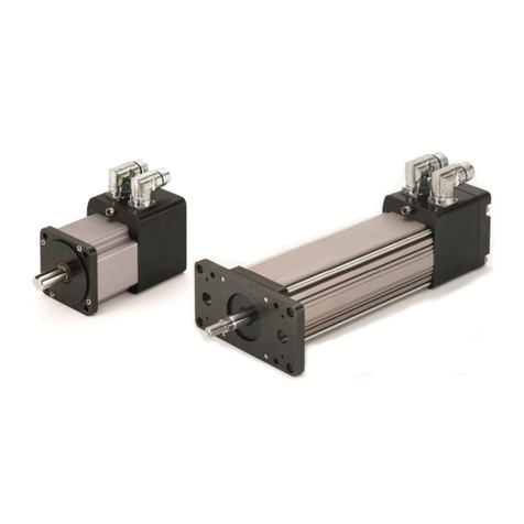
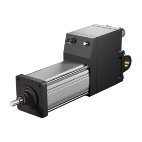
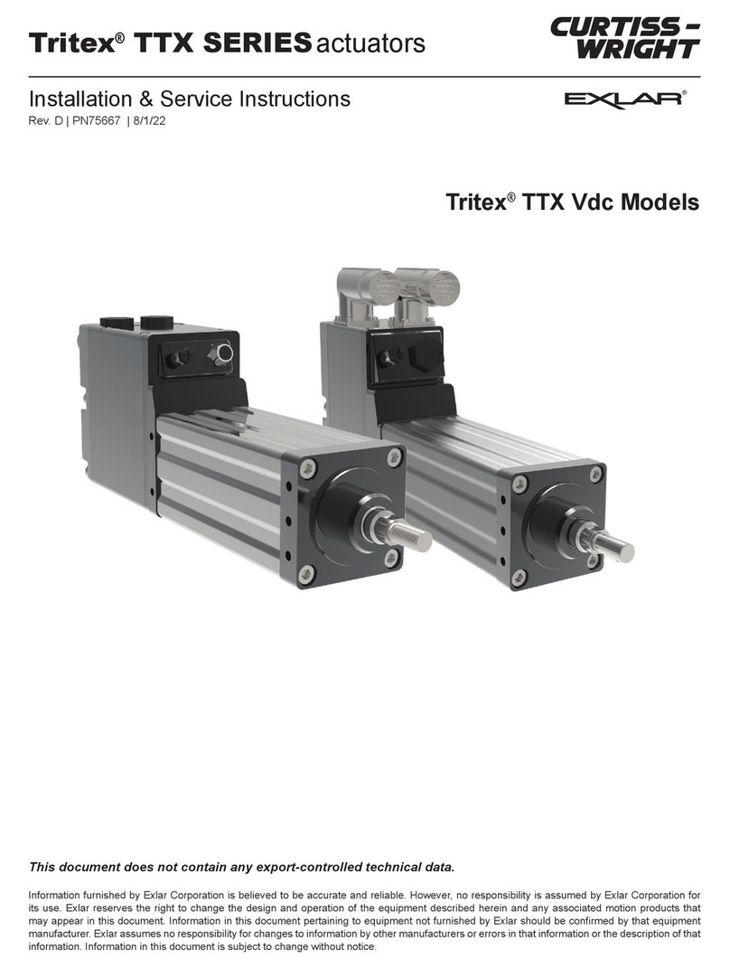
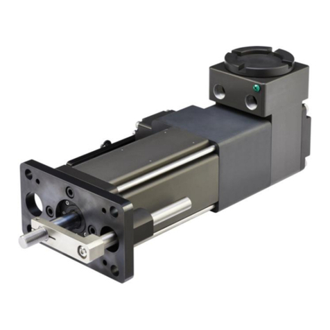
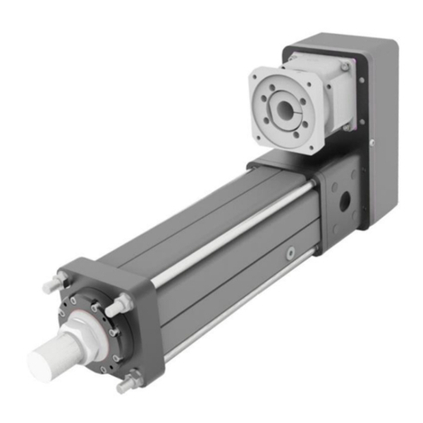
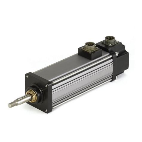
Exlar Curtiss-Wright Tritex II Series Manual

Curtiss-Wright | TRITEX II AC 75 Rev. KPN61928 7/12/2022
1
Tritex II®Series Actuators
240VAC Linear and Rotary Actuator
75 mm Frame Size
Installation and Service Manual
Information furnished by Exlar Corporation is believed to be accurate and reliable.
However, no responsibility is assumed by Exlar Corporation for its use. Exlar reserves the
right to change the design and operation of the equipment described herein and any
associated motion products that may appear in this document. Information in this document
pertaining to equipment not furnished by Exlar should be confirmed by that equipment
manufacturer. Exlar assumes no responsibility for changes to information by other
manufacturers or errors in that information or the description of that information. Information
in this document is subject to change without notice.
This document does not contain any export controlled technical data.

Curtiss-Wright | TRITEX II AC 75 Rev. KPN61928 7/12/2022
3
TABLE OF CONTENTS
Safety Considerations ............................................................................... 5
Warnings and Cautions......................................................................... 5
Underwriters Laboratories UL Recognized ........................................... 8
UL Certificate of Compliance ................................................................ 9
CE Declaration of Conformity.............................................................. 11
UK Declaration of Conformity.............................................................. 11
EU Declaration of Conformity.............................................................. 11
CSA Certified Product ......................................................................... 16
General Specifications ............................................................................19
Tritex II Overview ................................................................................ 19
Drive Specification for all Tritex 240 Volt Models................................20
Actuator Selections ............................................................................. 21
Linear Actuator Ordering Guide .......................................................... 22
Rotary Motor and Gearmotor Ordering Guide ....................................22
Mechanical Installation............................................................................24
Mounting and Operating Considerations ............................................24
Lubrication........................................................................................... 24
General Operation...............................................................................25
Mounting Configurations ..................................................................... 25
T2M Series Linear Actuator Anti-rotation Option ................................25
Outdoor and Wash Down Installations................................................ 26
Manual Drive Operating Instructions................................................... 27
Electrical Installation ............................................................................... 29
Introduction.......................................................................................... 29
Cable Entry.......................................................................................... 30
Grounding............................................................................................ 32
Shielding.............................................................................................. 33
AC Input Power ................................................................................... 34
Input Power Ratings ......................................................................34
AC Supplies NOT Requiring Transformers ...................................34
AC Supplies Requiring Transformers............................................37
Single Phase Isolation Transformer connections..........................38
Wire Size, Branch Circuit Protection and Overcurrent Protection....39
Power Terminal Wiring ..................................................................39
Power Connector Wiring ...............................................................41
Over Temperature Protection.............................................................. 41
Brake / Shunt Resistor Considerations ...............................................42

Curtiss-Wright | TRITEX II AC 75 Rev. KPN61928 7/12/2022
4
Logic and IO Power Supply................................................................. 44
Tritex Input and Output Wiring ......................................................46
Input/Output Connections.............................................................. 47
Digital Inputs.................................................................................. 49
Digital Outputs ............................................................................... 50
Actuator Brake Option ...................................................................51
Analog Input ..................................................................................53
Analog Output................................................................................ 54
Communications............................................................................54
PC Communications......................................................................56
IA4 Option board connections .......................................................57
AF Option, Absolute Feedback .....................................................60
Ethernet Options, EIP,TCP or ProfiNet IO .................................... 61
CANopen ....................................................................................... 63
Maintenance Procedures for Re-Greasing .............................................65
Maintenance Procedure for Roller Screw Re-Greasing......................65
Disassembly ..................................................................................65
Lubrication Maintenance ............................................................... 66
Grease Renewal............................................................................67
Reassembly...................................................................................67
Maintenance Procedures for Complete Re-Greasing .........................68
Disassembly ..................................................................................68
Lubrication Maintenance ............................................................... 69
Grease Renewal............................................................................69
Reassembly...................................................................................70
Accessories............................................................................................. 72
Cables ................................................................................................. 72
TTIOC-xxx I/O Cable..................................................................... 72
TTICO-xxx Communications Cable...............................................74
Communication Converter .................................................................. 75
Braking Resistor T2BR1...................................................................... 76
Returning a Product for Repair ...............................................................77

Curtiss-Wright | TRITEX II AC 75 Rev. KPN61928 7/12/2022
5
SAFETY CONSIDERATIONS
Warnings and Cautions
As with any electro-mechanical device, safety must be considered
during the installation and operation of your Tritex Series actuator.
Throughout this manual you will see paragraphs marked with CAUTION
and WARNING signs as shown below:
“WARNING”indicates the information following is essential
to avoiding a safety hazard.
“CAUTION”indicates the information following is necessary
for avoiding a risk of damage to the product or other
equipment.
General
Failure to follow safe installation guidelines can cause death
or serious injury. The voltages used in the product can
cause severe electric shock and/or burns and could be lethal. Extreme
care is necessary at all times when working with or adjacent to the
product. The installation must comply with all relevant safety legislation
in the country of use. The forces created by actuator could be lethal or
cause severe injury if proper protection is not provided to keep personnel
away from moving components.
System Design and safety for personnel
The actuator is intended as a component for professional
incorporation into complete equipment or a system. If
installed incorrectly, the actuator may present a safety hazard. The
actuator uses high voltages and currents, carries a high level of stored
electrical energy, and is used to control equipment which can cause
injury. Close attention is required to the electrical installation and the
system design to avoid hazards either in normal operation or in the event
WARNING
CAUTION
WARNING
WARNING

Curtiss-Wright | TRITEX II AC 75 Rev. KPN61928 7/12/2022
6
of equipment malfunction. System design, installation, commissioning
and maintenance must be carried out by personnel who have the
necessary training and experience. They must read this safety
information and this manual carefully.
None of the functions or features of the Tritex actuator may be
used to ensure safety of personnel, i.e. they must not be used for
safety-related functions.
For example, the actuators enable / disable, brake, stop/start and
forward/reverse functions are not sufficient for use in safety-critical
applications without additional independent channels of protection.
Careful consideration must be given to the functions of the actuator
which might result in a hazard, either through their intended behavior or
through incorrect operation due to a fault. In any application where a
malfunction of the actuator or its control system could lead to or allow
damage, loss or injury, a risk analysis must be carried out, and where
necessary, further measures taken to reduce the risk.- for example a
failsafe brake in case of loss of actuator braking power.
Never attempt to connect or disconnect the actuator
with power applied.
Dangerous voltages are present. Damage to equipment
and injury to personnel can result. Refer to the following warnings on
supply isolation and stored energy discharge time for more information.
Supply isolation
The AC supply or high voltage DC supply must be removed
from the actuator using an approved isolation device or
disconnect before any maintenance is performed except adjustments to
the settings or parameters as specified in the manual.
Risk of Electric Shock
Allow 3 minutes for Discharge Time
The actuator contains capacitors that remain charged to a
potentially lethal voltage for up to 3 minutes after the
supply has been removed. Do not remove cable or cover or touch power
wiring terminals until this discharge time has expired.
WARNING
WARNING
WARNING
3-Minutes

Curtiss-Wright | TRITEX II AC 75 Rev. KPN61928 7/12/2022
7
If connected by plug and socket
A special hazard may exist where the actuator is
incorporated into a system connected to the AC supply by a
plug and socket. The pins of the plug are not generally isolated from the
charge stored in the bus capacitor, so must be considered electrically
“hot” until the discharge time has expired. It is the responsibility of the
user to avoid any possibility of electric shock from the pins when they are
accessible.
Grounding - High Leakage Current
The drive must be grounded by a conductor sufficient to
carry all possible fault current in the event of a fault. This
equipment has high earth leakage current. You must comply with local
safety regulations with respect to minimum size and special installation
requirements on the protective earth conductor for high leakage current
equipment. The instructions for ground connections shown in this manual
must be followed.
Compatibility with Residual Current-operated
Protection Device (RCD)
This product can cause a DC current in the protective
earthing conductor. Where a residual current –operated protective (RCD)
or monitoring (RCM) device is used for protection in case of direct or
indirect contact, only an RCD or RCM of Type B is allowed on the supply
side of this product.
Hot Surface – Risk of Burn
Exposed surfaces of the actuator may exceed 70°C under
normal operation and can take a long time to cool,
resulting in a risk of burns when touched.
WARNING
WARNING
CAUTION
WARNING

Curtiss-Wright | TRITEX II AC 75 Rev. KPN61928 7/12/2022
8
Underwriters Laboratories UL Recognized
Tritex II 75 mm Linear and Rotary Actuators are marked “UL
Recognized” after passing a rigorous set of design and testing criteria
developed by Underwriters Laboratories UL 508C, UL 1004-1,
UL 1004-3 and UL 1004 -7. This UL logo indicates that UL certifies this
product to be safe when installed according to the installation instructions
and used in accordance with the product specifications and the following
conditions of acceptability:
The conditions of acceptability required by UL are:
•Drive input maximum continuous operating ratings:
Input Voltage (all models): 240 VAC, 1 Ф, 50/60 Hz
Drive/Motor Model
Stator
Input Continuous
Current (Arms)
T2M/R2M/R2G 075
1 Stack Stator
4.3
T2M/R2M/R2G 075
2 Stack Stator
4.0
T2M/R2M/R2G 075
3 Stack Stator
3.6
•Above full load ratings are at a maximum surrounding air
temperature of 40°C.
•Suitable for use on a circuit capable of delivering not more than
10,000 rms symmetrical amperes, 240 Volts maximum when
protected by Class CC or Class RK1 fuses, or when protected by a
circuit breaker having an interrupting rating.
•Integral solid state short circuit protection does not provide branch
circuit protection. Branch circuit protection must be provided in
accordance with the National Electrical Code and any additional local
codes.
•Use 14 AWG wire with insulation rated for 105°C input power and PE
terminals.
•Multiple connection options covered in the model mask
nomenclature in the report.
UL Recognized
UL File E353255

Curtiss-Wright | TRITEX II AC 75 Rev. KPN61928 7/12/2022
9
UL Certificate of Compliance

Curtiss-Wright | TRITEX II AC 75 Rev. KPN61928 7/12/2022
10

Curtiss-Wright | TRITEX II AC 75 Rev. KPN61928 7/12/2022
11
CE Declaration of Conformity
The Tritex II 75 mm Linear and Rotary Actuators are marked with the
“Conformité Européenne Mark” (CE Mark) after passing a rigorous set of
design and testing criteria. This label indicates the product meets
applicable electrical safety, and electromagnetic immunity and emissions
(EMC) standards when installed according to the installation instructions.
The conditions of acceptability required for CE are:
•Drive input maximum continuous operating ratings:
Input Voltage (all models): 240 VAC, 1 Ф, 50/60 Hz
Drive/Motor Model
Stator
Input Continuous
Current (Arms)
T2M/R2M/R2G 075
1 Stack Stator
4.3
T2M/R2M/R2G 075
2 Stack Stator
4.0
T2M/R2M/R2G 075
3 Stack Stator
3.6
•Above full load ratings are at a maximum surrounding air
temperature of 40°C.
•Field installation power connection wires: Use 2.5mm², 300 VAC
minimum rating, and 105º C minimum rating copper wires.
•Two externally connected ground wires must be used and connected
to protective earth ground (PE). Note: two PE connection terminals
are provided since touch is greater than 3.5mA. This wire is required
to be no less 2.5mm² since mechanical protection of is provided via
hard conduit or a cable assembly.
•This product is suitable for use on a circuit capable of delivering up
to 10,000 rms symmetrical amperes, 240 volts maximum, when
protected with by a Class RK1 or Class CC fuse or Inverse Time
Circuit Breaker, rated at 15 Arms.
•All cables must be shielded, with the outer shield bonded to
the case.
•When using cable glands use glands that connect the braided shield
of the cable directly to enclosure.
•When using connectors ensure that the outer shield of the cable is in
full contact with the connector housing. Connector housings must
conductive.

Curtiss-Wright | TRITEX II AC 75 Rev. KPN61928 7/12/2022
12
•Make ground connections as short as possible for low impedance.
•Keep cable runs as short as possible. Power and signal cables must
be separated and far as possible and only crossing them at right
angles as described in the Cable routing section of this manual.
•IP 66 rating:
•To maintain IP ratings, the RS485 cable or cap must be installed. All
other cable connections must be connected or sealed.

Curtiss-Wright | TRITEX II AC 75 Rev. KPN61928 7/12/2022
13

Curtiss-Wright | TRITEX II AC 75 Rev. KPN61928 7/12/2022
14

Curtiss-Wright | TRITEX II AC 75 Rev. KPN61928 7/12/2022
15
Per EU directives implemented on April 20th, 2016 the following requirement for
requirement must be followed by Importers and Distributors.
The requirements for importers include:
Importers shall indicate their name, registered trade name or registered trade mark and the
postal address at which they can be contacted on the apparatus (unless that is not
possible, in which case it should be included on the packaging or in an accompanying
document).
Importers shall ensure that the product is accompanied by instructions and safety
information in a language which can be easily understood by end-users, as determined by
the Member State concerned.
Importer is to translate the EU declaration of conformity into the languages required by the
member state(s), where the product is sold.” Importers shall keep a copy of the EU
declaration of conformity (for 10 years).
Importers shall provide a reasoned request from a competent national authority and provide
it with all the information and documentation in paper or electronic form necessary to
demonstrate the conformity of a product in a language which can be easily understood by
that authority.
Importers shall ensure that, while apparatus is under their responsibility, its storage or
transport conditions do not jeopardize its compliance with the safety objectives.
Importer shall corrective action necessary when they consider or have reason to believe
that the product is not in conformity with its directive(s).
The requirements for distributor include:
Distributors shall indicate their name, registered trade name or registered trade mark and
the postal address at which they can be contacted on the apparatus (unless that is not
possible, in which case it should be included on the packaging or in an accompanying
document).
Distributor shall ensure that apparatus is accompanied by instructions and safety
information in an appropriate language. Distributor shall translate the EU declaration of
conformity into the languages required by the member state(s), where the product is sold.”
Distributors shall keep a copy of the EU declaration of conformity (for 10 years).
Distributor shall ensure that, while apparatus is under their responsibility, its storage or
transport conditions do not jeopardize its compliance with the safety objectives.
Distributor shall corrective action necessary when they consider or have reason to believe
that the product is not in conformity with its directive(s).

Curtiss-Wright | TRITEX II AC 75 Rev. KPN61928 7/12/2022
16
CSA Certified Product
The Tritex II 75 mm Linear and Rotary Actuators are marked as shown
after passing a rigorous set of design and testing criteria developed by
CSA International (C22.2 No. 139) and Underwriters Laboratories
(UL 429). This label indicates that CSA certifies this product to be safe
when installed according to the installation guidelines and used with the
scope of the product specifications.
The conditions of acceptability required by CSA are:
•Drive input maximum continuous operating ratings
Input Voltage (all models): 240 VAC, 1 Ф, 50/60 Hz
Drive/Motor Model
Stator
Input
Continuous
Current (Arms)
Torque Rating
max.
T2M/R2M/R2G 075
1 Stack
Stator
4.3
12.0 lbf-in
T2M/R2M/R2G 075
2 Stack
Stator
4.0
22.0 lbf-in
T2M/R2M/R2G 075
3 Stack
Stator
3.6
30.0 lbf-in
•Installation Requirements
- Hazardous Location (Class I Division 2 Group A, B, C, D)
installations – ½” rigid conduit with NPT connections and use
UL approved copper only wires, 14 AWG, 300 VAC minimum
rating, and 105º C minimum rating shall be used.
- For other non-hazardous locations:
• Use the above connection method, or
• Cable with connector assemblies, or
• Cables with cable glands are permitted.
For additional information on cable installations or part numbers
contact Exlar Corporation.
•Branch circuit protection must be provided. Reference the
manual’s electrical installation section for fuse and circuit breaker
options. Note: branch circuit protection must be located outside
of the hazardous location environment,
•The full load ratings are at 40°C ambient temperature and
ratings are derated linearly from 40°C to 65°C.
•These conditions of acceptability only apply to units with a CSA
mark on the product label.

Curtiss-Wright | TRITEX II AC 75 Rev. KPN61928 7/12/2022
17

Curtiss-Wright | TRITEX II AC 75 Rev. KPN61928 7/12/2022
18

Curtiss-Wright | TRITEX II AC 75 Rev. KPN61928 7/12/2022
19
General Specifications
Tritex II Overview
Tritex II is Exlar’s advanced family of integrated drives. This manual
applies to 75 mm frame size only with 240VAC input power. All of the
required power components and motion processor are contained in the
actuator housing.
Basic Block Diagram with SIO Option
Table of contents
Other Exlar Controllers manuals
Popular Controllers manuals by other brands
Johnson Controls
Johnson Controls Penn P216 Series installation instructions
BENDIX
BENDIX ULTIMATE TOW Installation & operating instructions
MOTECK
MOTECK CIS3 user guide
Gossen MetraWatt
Gossen MetraWatt R2700 operating instructions
Matelec
Matelec FPC-12720 quick start guide
Hunter
Hunter Pro-C Product information


