EXTERIS AUDIO EA200SW User manual

www.ExterisAudio.com
Copyright © 2011-2017 Exteris Audio, LLC All Rights Reserved.
Model EA200SW
OWNER’S MANUAL
Outdoor Audio Solutions:
Unique Outdoor
Speakers & Stereos
TM
Hardwired
Outdoor Stereo Speakers

TABLE OF CONTENTS
Design Features.................................................................. 1
Introduction.......................................................................... 2
Install Location..................................................................... 2
Cautions............................................................................... 2
Inspection............................................................................. 2
Contents............................................................................... 3
Unpacking............................................................................ 3
Assembly/Installation........................................................... 5
Audio Connections............................................................... 9
Maintenance........................................................................ 10
Warranty.............................................................................. 11
Specifications..............................................Inside Back Cover
WARNING! Plastic bags are used in the packaging of your
speakers. To avoid danger of suffocation, please
keep these bags away from babies and children.
Small parts are also contained with your
speakers to complete assembly and may present
a choking hazard for babies and small children as
well.
Integrated handles are designed for lifting when
cabinet is in the upright position only!
Correct Wrong
Specifications
Drivers per Speaker:
Tweeter 1 - 1” Titanium dome / ferrofluid cooled
Woofer - upper 1 - 6.5” Polypropylene cone with rubber
surround
Woofer - lower 2 - 6.5” Polypropylene cone with rubber
surround mounted in compound/isobaric
configuration
Electrical:
Frequency Response Overall 35Hz - 20kHz / lower -3db
limit 45Hz
Crossover 12db/oct at 3500Hz
Air core inductors and
polypropylene capacitors
Nominal Impedance 8 ohms
Power Handling 100 watts rms / 150 watts peak
SPL 86db 1W/1m
Inputs Gold-plated / accepts banana
connectors or wire (8ga. max)
Dimensions:
Cabinet Size (as installed) 35-7/8” H x 8-7/8” W x 9-1/4” D
Footprint Size 12” W x 9-1/4” D
Cabinet Weight Upper ~36lbs. ea. / Lower ~40lbs. ea.

1
12
damage in transit. If original shipping containers are not available, the
appropriate packaging can be ordered by calling us.
This Warranty is not transferable and does not cover product purchased,
serviced or used outside the United States. The Warranty does not
extend to the elimination of externally generated static or noise, or to
costs incurred for the installation, removal or reinstallation of the product.
This Warranty does not apply to any product or part thereof which, in the
opinion of the Company, has suffered or been damaged through
alteration, improper installation, mishandling, misuse, neglect, accident,
disaster, improper maintenance, failure to follow instructions, excess
voltage or current caused by lightning, power line fluctions, or by faulty
12vac power supply transformer, or any repairs not specifically
authorized by the Company.
THE EXTENT OF THE COMPANY’S LIABILITY UNDER THIS
WARRANTY IS LIMITED TO THE REPAIR OR REPLACEMENT
PROVIDED ABOVE AND, IN NO EVENT, SHALL THE COMPANY’S
LIABILITY EXCEED THE PURCHASE PRICE PAID BY PURCHASER
FOR THE PRODUCT.
This Warranty is in lieu of all other express warranties or liabilities. ANY
IMPLIED WARRANTIES, INCLUDING ANY IMPLIED WARRANTY OF
MERCHANTIBILITY OR FITNESS FOR A PARTICULAR PURPOSE,
SHALL BE LIMITED TO DURATION OF THIS WARRANTY. IN NO
CASE, SHALL THE COMPANY BE LIABLE FOR ANY
CONSEQUENTIAL OR INCIDENTAL DAMAGES WHATSOEVER. No
person or representative is authorized to assume for the Company any
liability other than expressed herein in connection with the sale of this
product.
This warranty gives you specific legal rights, and you may have other
rights which vary from state to state. Some states do not allow the
exclusion or limitations of consequential damages, so the above
limitations may not apply to you. Interpretation and enforcement of this
terms and conditions shall be governed by the laws of the State of Texas.
Front View
Titanium Dome
Tweeter
Polypropylene
Woofer Modular
Cabinets
>Travertine
Veneer
> Polished
> Sealed
Bass Port
Gold Plated
Terminals
Recessed Handle
Solid Aluminum Supports w/ Adjustable Feet
Perforated
Aluminum Grills
> Exterior Grade
Powder Coat
> Reversible
Safety Bracket
Recessed Handle
Rear View
Cement
Composite
Backs
> Exterior Grade
Acrylic Paint
Cabinet
Alignment Pins
> Stainless Steel
Design Features
Polypropylene
Woofer
Perforated
Aluminum Grills
> Exterior Grade
Powder Coat
> Reversible
Bass Port
Model EA200SW
TM
TM
Model EA200SW

11
2
Introduction
Congratulations, and thank you, for your purchase of our EA200SW
outdoor speaker system! We are confident you will agree our unique one
of a kind stone veneer cabinets add a touch of indoor elegance and
styling to your outdoor living space that you will appreciate for many
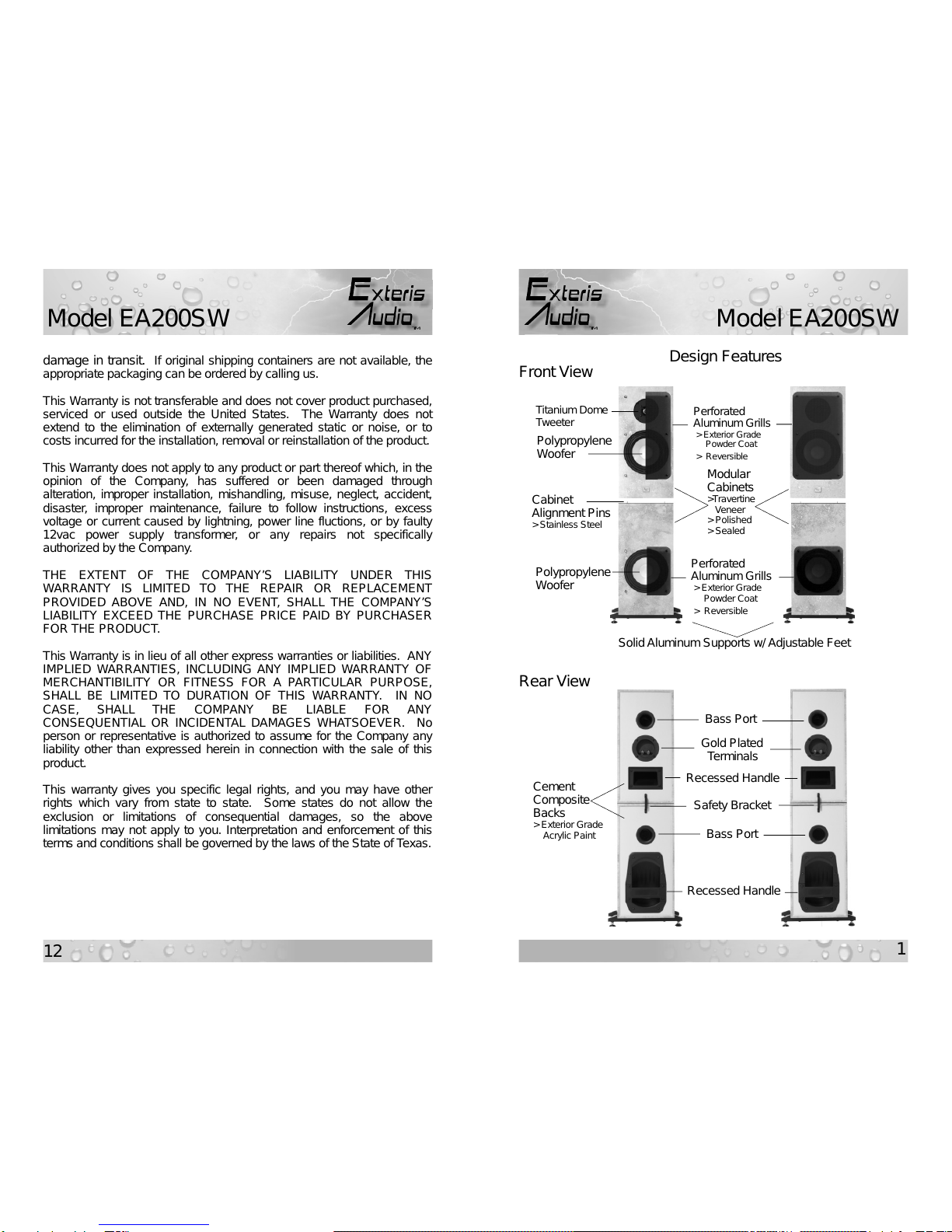
years to come. EA200SW speakers incorporate dual woofer drivers
mounted in a compound/isobaric configuration in each lower cabinet,
which provides improved bass response. Please read this manual
thoroughly before attempting assembly and installation.
Install Location
Our speaker systems are designed and tested to withstand the rigors of
open air installation. However, an install location with some shielding
from sun, direct moisture exposure, and placement in front of a wall is
the ideal location from the standpoint of minimizing maintenance,
extending the “like new” appearance, and improving bass performance.
Separation of the speakers should be roughly six feet apart, if possible.
As with all our speakers, EA200SW’s will look and sound great if you
choose to use them indoors as well.
Cautions
Our outdoor speaker systems are fully weatherproof and water resistant,
when installed in accordance with this Owner’s Manual. Our speaker
systems are not waterpoof, and must never be submerged.
Inspection
Inspect all boxes and contents for any signs of hidden or concealed
damage. If any damaged is discovered, contact us immediately, if
possible, and within no more than five business days after receipt.
NOTE! Water should never be streamed directly into speaker drivers
for the purpose of cleaning.
1/3/5 Year Limited Warranty
Exteris Audio, LLC (the “Company”) warrants this outdoor speaker
system, whether used outdoors or indoors, against defects in material
and workmanship under normal use to the original retail customer for
the following periods from the date of original purchase:
1 Year – Dc power supplies, fans, and installed stereo components;
3 Years –All tweeter, woofer, and subwoofer drivers, including
electronic crossovers. Powder coat finish on speaker
grills, and base supports are warranted against peeling
and blistering due to adhesion loss only. Chipping and
fading are not covered; and
5 Years – Speaker cabinet glue joints and attached cabinet
hardware, e.g. terminals, bass ports, recessed handles,
etc. Stone veneer is not warranted against naturally
occurring cracks, surface defects, and finish.
To obtain repair or replacement within the terms of this Warranty,
customer must contact Company via phone or email to verify proof of
purchase and obtain a Return Authorization Number. Company will
accept no product for return without prior consent. Company at its
option, will: 1) correct the product defect without charge for parts and
labor; or 2) replace the defective product with one of the same or
similar design without charge for parts and labor. New and/or
reconditioned parts may be used for warranty repairs. Repaired or
replaced parts and products are warranted for the remainder of the
original warranty period. Customer must pay all return shipping and
insurance costs for warranty service, and Company will pay all
shipping and insurance cost for return shipping to customer in the
contiguous United States.
Due to the weight of our products and risk of shipping damage if
improperly packaged, all authorized product warranty returns must be
shipped in the original shipping containers, along with proof of
purchase, prepaid insured. Customer assumes all risk of loss or
Model EA200SW
TM
TM
Model EA200SW

3
10
Contents
In addition to the four cabinets, you will find the following items included
that will be needed to complete assembly and install:
Description Qty
1. 14” x 8” perforated aluminum speaker grill 02
2. 8” x 8” perforated aluminum speaker grill 02
3. 12” x 5/8” aluminum base support 04
4. Adjustable feet w/ locknut 08
5. Safety bracket 02
6. #6-32 x 5/32” stainless button head cap screw 20
7. #8-32 x 1/4” stainless button head cap screw w/ washer 04
8. #10-32 x 1” phillips head stainless machine screw 08
9. 5/64” hex wrench for #6-32 screws 01
10. 3/32” hex wrench for #8-32 screws 01
11. 1/4”x3/4” & 1/4”x1” stainless steel alignment pins 04 ea.
12. Owner’s Manual 01
Unpacking
1. Move all boxes as close as possible to the final installation location.
2. If system was shipped, carefully open each outer shipping box and
remove the inner box which contains the speaker cabinet and parts.
3. Referring to Fig. 1 below, carefully remove all loose components and
parts from each box as designated by the corresponding letter:
A, C: Boxes for these cabinets will each contain one (1) 14” x 8”
perforated aluminum grill. Remove grills and place on a flat
surface.
Fig. 1
Maintenance
Your new speaker system is made of very rugged materials and
components to ensure years of trouble-free performance. However, in
order to extend the “like-new” appearance and life well beyond the
warranty period, proper maintenance procedures are necessary and
summarized as follows:
Cabinets – Since all natural stone has some level of porosity, it is
important that a high quality sealer be used periodically.
We use, and recommend, a water based color enhancing
penetrating stone sealer to keep the veneer finish looking
its best. If our systems are exposed directly to rain, snow
and ice, then treating the cabinets every 6 months is
recommended. Indirect exposure, will reduce the
application of fresh sealer to about every 12 months. A
good test is to clean the top of a cabinet and sprinkle a few
drops of water to see if they bead on the surface. If you
don’t see a nice round water bead, then it’s time to reapply
sealer. To remove dirt build-up, simply wipe cabinet with
soft damp cloth.
Grills – Dirt/contaminate build-up from the powder coated
aluminum grills should be removed as needed or every 3
months by cleaning each grill in a solution of mild non-
abrasive liquid detergent and water using a soft brush,
being careful not to apply too much pressure, which may
scratch the finish or bend the grill. Regular cleaning is
especially important in coastal areas.
Supports – Same as Grills above, but use only fresh water (no
detergent), being careful not to disturb the rubber gasket
installed on top side of supports, which are mounted with
waterproof adhesive.
Woofers – To maximize woofer driver life, gently wiping dirt from the
rubber surround with a soft damp cloth and applying a coat
of Armor All® protectant will help prevent rot and extend
life. It’s recommended that cleaning and treatment take
place each time the speaker grills are removed for
cleaning.
Tweeters – DO NOT attempt to clean.
AC
BD
Model EA200SW
TM
TM
Model EA200SW

9
4
B, D: Boxes for these cabinets will each contain one (1) 8” x 8”
perforated aluminum grill and two (2) aluminum base supports.
Remove for later installation.
Note: All remaining parts for assembly/install will be located in a
separate small parts box.
4. Now that all loose components and parts are removed, place boxes
on their side on a solid non-scratch surface, open bottom flaps of
boxes, and, from the front or rear, carefully push cabinet until
completely free of box. Cabinet should be resting on four (4) foam
corners. Refer to Fig. 2 below for safe removal of each
speaker/cabinet.
NOTE! Cabinets are heavy, remove carefully. Seek help if needed.
5. From boxes with cabinets A,C remove the top four (4) foam corner
protectors and place in the up position on a solid surface. Next, move
each cabinet and place it face-up, with the back side resting on/in the
foam corner pieces as shown in Fig. 3.
Audio Connections
Model EA200SW speakers are designed to be connected to an external
/indoor stereo amplifier as noted in Fig. 9. If speaker wires are to be run
through walls, please check local building codes for appropriate wiring to
use.
In order to maintain the highest audio fidelity possible, the following
speaker cable lengths versus wire gauges are recommended:
• Cable runs up to 10 feet: 18 ga.
• Cable runs up to 25 feet: 16 ga.
• Cable runs up to 45 feet: 14 ga.
• Cable runs up to 65 feet: 12 ga.
Fig. 3
Cabinets A ,C
Fig. 2
Fig. 9
+
-
+-
To
Stereo/
Amplifier
Right Left
Model EA200SW
TM
TM
Model EA200SW

5
8
each of the right and left tower arrangements. See Fig. 8 for
details.
7. Install four (4) Speaker Grills on cabinetsA,B,C, & D.
7a. Locate two (2) 14”x8” and two (2) 8”x 8” perforated aluminum
speaker grills and twenty (20) #6-32 x 5/32” stainless button
head cap screws.
7b. Install one (1) ea. speaker grill on cabinet A,B,C, & D using
provided 5/64” hex wrench and twenty (20) #6-32 x 5/32”
stainless button head cap screws. Install screws just enough to
catch the first few threads without fully tightening until all screws
are in place. Once all screws in place, snug screw heads to the
surface of the grill with light pressure.
NOTE! Be very careful not to overtighten screws.
7c. Carefully move assembled cabinets into final position. Using a
bubble level, adjust feet to level top or provide a slight slope to
the rear of the speaker cabinets to aid in water run-off, if direct
exposure to rain/snow is expected.
8. CONGRATULATIONS! Assembly is now complete and speakers are
ready to be connected.
6. From boxes with cabinets B,D remove the top four (4) foam corner
protectors and place two (2) in the up position on a solid surface.
Next, locate the four (4) small blue foam squares provided and place
two (2) for each cabinet as shown in Fig. 4. Finally, move each
cabinet and place it face-up, with the back side resting on/in the foam
corner pieces as shown in Fig. 4. This allows clearance for
installation of the Base Supports.
Note: Save (as many as possible) boxes/shipping materials for future
transport or shipment.
7. You are now ready to proceed to assembly and installation.
Assembly/Installation
1. Mount cabinet Base Supports to lower cabinets B and D.
1a. Locate four (4) aluminum Base Supports and eight (8) #10-32 x 1”
stainless machine screws.
1b. Using a phillips screwdriver, mount 2 ea. aluminum Base
Supports to the bottom of cabinets B and D with eight (8) #10-32
x 1” stainless machine screws.
NOTE! Be careful not to overtighten screws.
1c. Locate eight (8) Adjustable Feet with locknuts and thread two (2)
into each of four (4) Base Supports until snug.
2. Raise two (2) bottom cabinets B and D to their upright position.
2a. Locate four (4) stainless 1/4” x 3/4” and four (4) 1/4” x 1”
alignment pins.
Fig. 4
Blue Foam
Cabinets B,D
Blue Foam
Fig. 8
Safety Brackets
Install Here
Model EA200SW
TM
TM
Model EA200SW

7
6
2b. Install eight (8) ea. alignment pins into top of cabinet B and D as
shown in Fig. 5.
NOTE! Be very careful to install ONLY 1/4” x 3/4” pins in back holes
and 1/4” x 1” pins in front holes.
3. Cabinets B and D are now ready for placement in their final installed
location.
4. Move cabinets B and D to install location.
4a. Using the recessed handle in the back of cabinet B and D insert
right or left hand into handle, steady the top of the cabinet with
your other hand as noted in Fig. 6, carefully perform a test lift to
ensure you can safely carry the cabinet. If in doubt, seek help.
Once you are satisfied you can carry the weight, carefully lift and
move cabinet B and D to its final install location.
5. Move cabinet A and C to install location and mount to cabinet B
and D.
5a. Using the recessed handles in the backs of cabinets A and C,
insert right or left hand into handle, steady the top of the cabinet
with your other hand as noted in Fig. 7, carefully perform a test
lift to ensure you can safely carry the cabinet. If in doubt, seek
help.
5b. Once you are satisfied you can carry the weight and guide the
speaker cabinet over the bottom cabinet, proceed to move each
cabinet to the same location as cabinets B and D.
5c. Referring to note below, place cabinet A (S/Nx) over cabinet B
(label with letter B) and align cabinet exterior edges until top
alignment bushings mate to bottom alignment pins, being careful
not to allow the top cabinet to drop forcefully to top of bottom
cabinet. Once alignment achieved, slowly lower the top cabinet
on to the bottom cabinet.
5d. Repeat above procedure for cabinet C (S/Nx+1) and D (label with
letter D).
Note: Each upper speaker cabinet has a serial number label located
on the recessed handle. These serial numbers are sequential
and are numbered as follows: S/Nx = cabinet A, S/Nx+1 =
cabinet C. For example, S/N 1 = A and S/N 2 = C. Each
lower speaker cabinet has a label with the letter B or D located
on the recessed handle.
6. Install two (2) Safety Brackets on rear of mounted speaker cabinets.
6a. Locate two (2) Safety Brackets, four (4) #8-32 x 1/4” stainless
button head cap screws and four (4) washers.
6b. Using the provided 3/32” hex wrench, install the safety bracket on
Fig. 6
Fig. 7
Install 4 - 1/4” x
3/4” pins at back.
Install 4 - 1/4” x
1” pins at front.
1 2 3 4
Fig. 5
BD
Model EA200SW
TM
TM
Model EA200SW
Table of contents
Other EXTERIS AUDIO Speakers manuals