9
4
NOTE! Cabinet may be too heavy for some people to remove
carefully and safely; seek help if needed. Also, save boxes/shipping
materials for future transport or shipment.
5. You are now ready to proceed to installation.
Installation
1. Identify mounting wall for speaker cabinet. Mounting location must be
within five feet of an approved outdoor 120vac outlet. If an outdoor
outlet in not within 5 feet, a certified electrician will need to extend the
power cable to required length in accordance with local codes and
regulations. Note! The speaker system should not be opened in
order to extend the cable length.
1a. Determine appropriate mounting height for your specific outdoor
space/arrangement. There are no hard and fast rules here, but a
top of cabinet height of approximately 60 inches is
recommended. This height can be raised or lowered depending
on your particular needs.
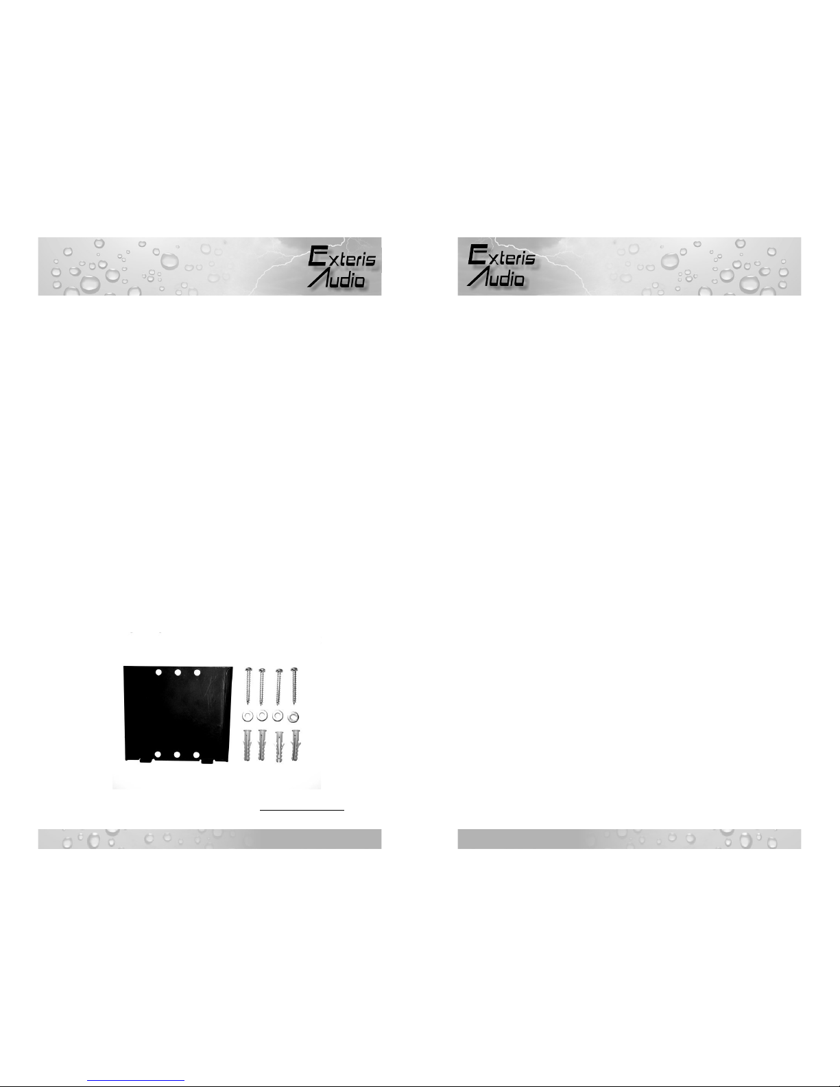
2. Once the mounting location/height is determined, locate the Wall
Mounting Plate [WMP] and associated hardware as shown in Fig. 1.
The WMP can be used as a template for marking the mounting holes
to be drilled.
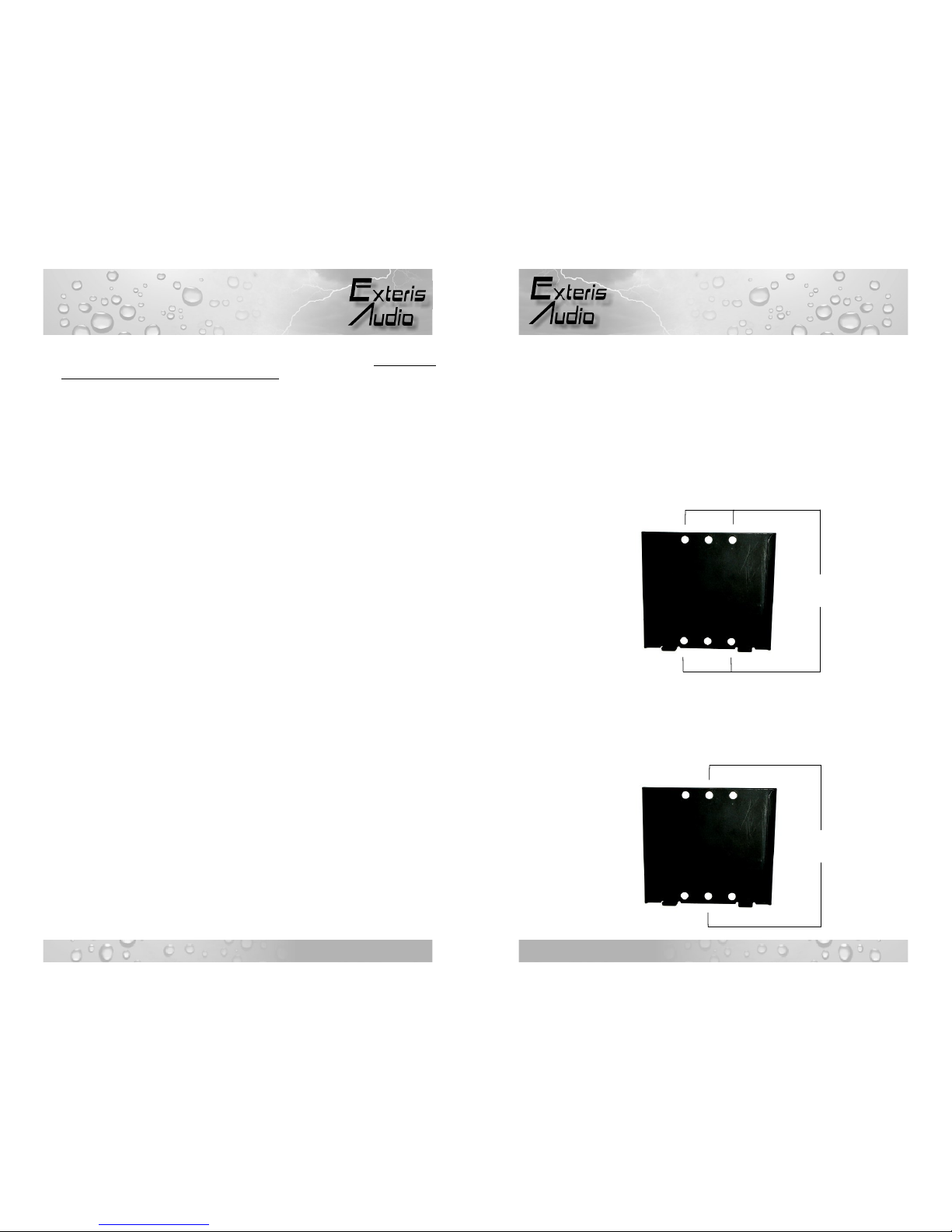
2a. Place the WMP against the wall surface narrow end down, using a
level on top, level the WMP then mark the hole locations. A
1/3/5 Year Limited Warranty
Exteris Audio, LLC (the “Company”) warrants this outdoor speaker
system, whether used outdoors or indoors, against defects in material
and workmanship under normal use to the original retail customer for
the following periods from the date of original purchase:
1 Year – Dc power supplies, fans, and installed stereo/amplifier
components;
3 Years – All tweeter, woofer, and subwoofer drivers, including
electronic crossovers. Plastic speaker grills. Powder coat
finish on aluminum speaker grills, and base supports are
warranted against peeling and blistering due to adhesion
loss only. ; and
5 Years – Speaker cabinet glue joints and attached cabinet
hardware, e.g. terminals, bass ports, recessed handles,
etc. Stone veneer is not warranted against naturally
occurring cracks, surface defects, and finish.
To obtain repair or replacement within the terms of this Warranty,
customer must contact Company via phone or email to verify proof of
purchase and obtain a Return Authorization Number. Company will
accept no product for return without prior consent. Company at its
option, will: 1) correct the product defect without charge for parts and
labor; or 2) replace the defective product with one of the same or
similar design without charge for parts and labor. New and/or
reconditioned parts may be used for warranty repairs. Repaired or
replaced parts and products are warranted for the remainder of the
original warranty period. Customer must pay all return shipping and
insurance costs for warranty service, and Company will pay all
shipping and insurance cost for return shipping to customer in the
contiguous United States.
Due to the weight of our products and risk of shipping damage if
improperly packaged, all authorized product warranty returns should
be shipped in the original shipping containers, along with proof of
purchase, prepaid insured. Customer assumes all risk of loss or
damage in transit. If original shipping containers are not available, the
appropriate packaging can be ordered by calling us.
WMP
Lag Screws
Masonry
Anchors
TM
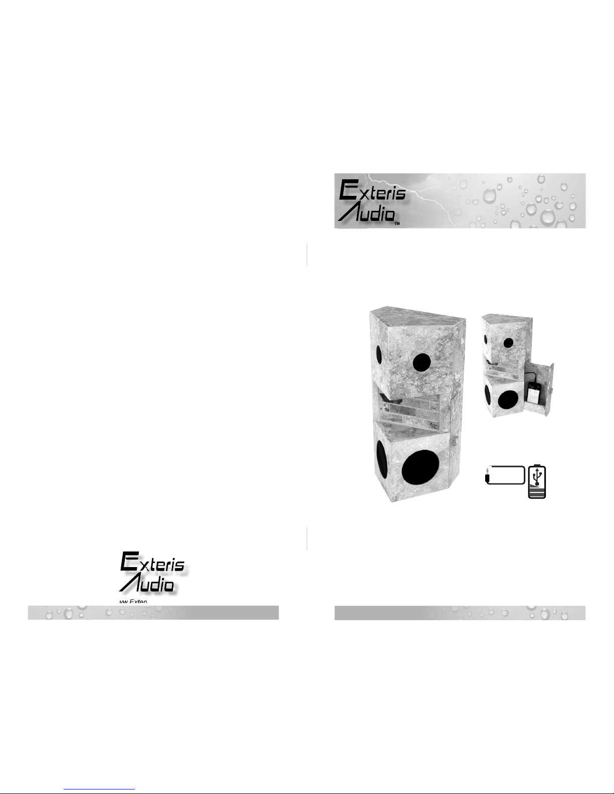
EA500CSA
TM
EA500CSA
Fig. 1