EXTERIS AUDIO EA300SW User manual

www.ExterisAudio.com
Copyright © 2011-2017 Exteris Audio, LLC All Rights Reserved.
Outdoor Audio Solutions:
Unique Outdoor
Speakers & Stereos
TM
Stand-Alone
Outdoor Stereo/Speakers
Model EA300SW
OWNER’S MANUAL

TABLE OF CONTENTS
Design Features.................................................................. 1
Introduction.......................................................................... 2
Inspection............................................................................ 2
Install Location and Cautions.............................................. 2
Contents.............................................................................. 3
Unpacking............................................................................ 3
Assembly/Installation........................................................... 5
Audio/Power Connections................................................... 10
Maintenance........................................................................ 11
High and Low Temperature Protection.................................13
Warranty...............................................................................14
Specifications.......................................................................16
WARNING! Plastic bags are used in the packaging of your
speakers. To avoid danger of suffocation, please
keep these bags away from babies and children.
Small parts are also contained with your
speakers to complete assembly and may present
a choking hazard for babies and small children
as well.
* These specs provided for reference since EA300SW speakers are
not intended to be driven from an external amplifier. However, if
desired, the two upper speakers can be used with an external stereo
amplifier.

1
16
Specifications
Drivers per Pair:
Tweeter 2 - 1” Titanium dome / ferrofluid cooled
Woofer 2 - 6.5” Polypropylene cone with rubber
surround
Subwoofer 2 - 6.5” Polypropylene cone with rubber
surround
Electrical:
Frequency Response Overall 35Hz - 20kHz
Lower -3db limit 42Hz
Crossover-tweeter/woofer 12db/oct at 3500Hz
Air core inductors and
polypropylene capacitors
Crossover-subwoofer 12db/oct at 120Hz
Nominal Impedance* 4 ohms
Power Handling* 75 watts rms / 100 watts peak
SPL* 86db 1W/1m
Inputs Gold-plated / accepts banana
connectors or wire (8ga. max)
Dimensions:
Cabinet Size (as installed) 35-7/8” H x 8-7/8” W x 9-1/4” D
Footprint Size 12” W x 9-1/4” D
Cabinet Weight Upper ~36lbs. ea.
Lower (w/stereo) ~43lbs.
Lower (w/o stereo) ~36lbs
AM/FM/CD Stereo: Please see enclosed AM/FM/CD
owner’s manual for manufacturer’s
specifications
Front View
Rear View
Titanium Dome
Tweeter
Polypropylene
Woofer
Bass Port
Gold Plated
Terminals
Recessed Handle
Bass Port
Gold Plated
Terminals Antenna
Cooling Fan Intake Filter
Aluminum Supports w/ Adjustable Feet
Polypropylene
Subwoofer
Safety Bracket
12vac Input
Recessed
Handle
Cement
Composite
Backs
> Exterior Grade
Acrylic Paint
I/R Remote
Receiver
Stereo
Access
Door
Perforated
Aluminum Grills
> Exterior Grade
Powder Coat
> Reversible
Perforated
Aluminum Grills
> Exterior Grade
Powder Coat
> Reversible
Modular
Cabinets
> Travertine
Veneer
> Polished
> Sealed
Design Features
Cabinet
Alignment
Pins
> Stainless Steel
Model EA300SW
TM
TM
Model EA300SW

215
Introduction
Congratulations, and thank you, for your purchase of our EA300SW
outdoor speaker system! We are confident you will agree our audio
products add a touch of indoor elegance and styling to your outdoor
living space that you will appreciate for many years to come. Besides
our unique one of a kind stone veneer cabinets, your new speakers
include many other innovative features, such as:
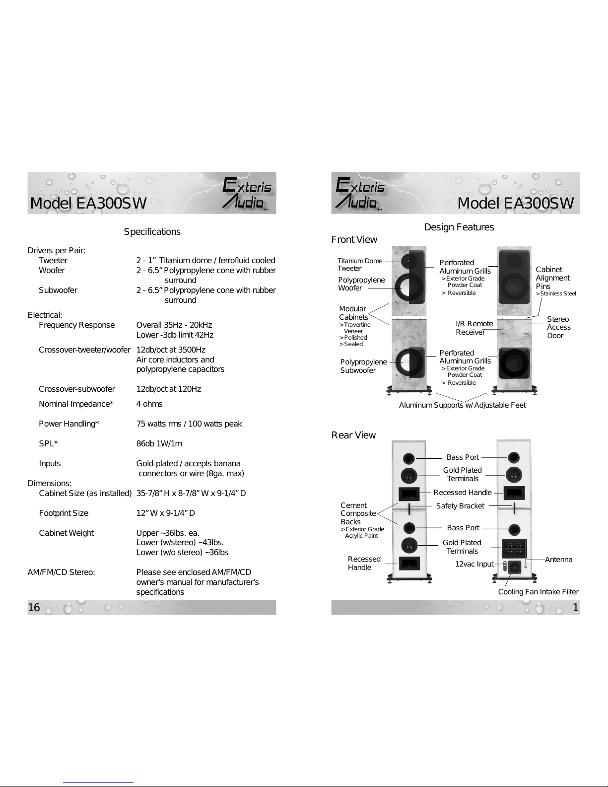
• integrated low voltage marine grade AM/FM/CD stereo electronics
with conformally coated circuit boards to protect against moisture;
• integrated powered dual subwoofers;
• reversible speaker grills;
• remote/extended run power via 12vac outdoor transformer;
• custom low voltage/high current audiophile dc power supply;
• high and low temperature sensing for ventilation and heat.
Please read this manual thoroughly before attempting assembly and
installation. Inspection
Inspect all boxes and contents for any signs of hidden or concealed
damage. If any damage is discovered, contact us immediately, if
possible, and within no more than five business days after receipt.
Install Location and Cautions
EA300SW’s use only low 12vac/dc voltages, and are safe to place in any
outdoor environment, including wet locations.
Although, our speaker systems are designed and tested to withstand the
rigors of open air installation, an install location with some shielding from
sun, direct moisture exposure, and placement in front of a wall is the
ideal location from the standpoint of minimizing maintenance, extending
the “like new” appearance, and improving bass performance.
A special note about sun exposure and heat: Placing this system in
direct sunlight will potentially generate enough heat to activate the high
temperature shut-down safety circuit, which deactivates power while
keeping the forced air ventilation fan running. The system will reset once
temperatures return to a safe level. An install location with some
shielding from direct sun, especially in the summer, or system operation
when ambient temperatures are lower will help minimize the occurrence
of system shut-downs.
This Warranty is not transferable and does not cover product purchased,
serviced or used outside the United States. The Warranty does not
extend to the elimination of externally generated static or noise, or to
costs incurred for the installation, removal or reinstallation of the product.
This Warranty does not apply to any product or part thereof which, in the
opinion of the Company, has suffered or been damaged through
alteration, improper installation, mishandling, misuse, neglect, accident,
disaster, improper maintenance, failure to follow instructions, excess
voltage or current caused by lightning, power line fluctions, or by faulty
12vac power supply transformer, or any repairs not specifically
authorized by the Company.
THE EXTENT OF THE COMPANY’S LIABILITY UNDER THIS
WARRANTY IS LIMITED TO THE REPAIR OR REPLACEMENT
PROVIDED ABOVE AND, IN NO EVENT, SHALL THE COMPANY’S
LIABILITY EXCEED THE PURCHASE PRICE PAID BY PURCHASER
FOR THE PRODUCT.
This Warranty is in lieu of all other express warranties or liabilities. ANY
IMPLIED WARRANTIES, INCLUDING ANY IMPLIED WARRANTY OF
MERCHANTIBILITY OR FITNESS FOR A PARTICULAR PURPOSE,
SHALL BE LIMITED TO DURATION OF THIS WARRANTY. IN NO
CASE, SHALL THE COMPANY BE LIABLE FOR ANY
CONSEQUENTIAL OR INCIDENTAL DAMAGES WHATSOEVER. No
person or representative is authorized to assume for the Company any
liability other than expressed herein in connection with the sale of this
product.
This warranty gives you specific legal rights, and you may have other
rights which vary from state to state. Some states do not allow the
exclusion or limitations of consequential damages, so the above
limitations may not apply to you.
Interpretation and enforcement of this terms and conditions shall be
governed by the laws of the State of Texas.
IMPORTANT! All warranty returns of our Model EA300SW product,
must have the two CD Unit transit screws reinstalled prior to return
to prevent transit/shipping damage. Any returns received without
the two CD Unit transit screws in place will VOID CD Unit one year
warranty regardless of reason for warranty return.
TM
Model EA300SW
Model EA300SW
TM

3
14
Please be reminded that the AM/FM/CD player installed in your system
has a removable faceplate/control panel and IR remote control. The
faceplate can be removed and stored in its protective case. Both the
faceplate and IR remote should be stored indoors when not in use.
Also, our outdoor speaker systems are fully weatherproof and water
resistant, when installed in accordance with this Owner’s Manual. Our
speaker systems are not waterpoof, and must never be submerged.
Contents
In addition to the four speaker cabinets, you will find the following items
included that will be needed to complete assembly and install:
Description Qty
1. 14” x 8” perforated aluminum speaker grill 02
2. 8” x 8” perforated aluminum speaker grill 02
3. 12” x 5/8” aluminum base support 04
4. Adjustable feet w/ locknut 08
5. Safety bracket 02
6. 1/2” hole plug 02
7. 3/4” x 23/32” winterizing port plug 01
8. 12vac solderless banana plugs 02
9. #6-32 x 5/32” stainless button head cap screw 20
10. #8-32 x 1/4” stainless button head cap screw w/ washer 04
11. #10-32 x 1” phillips head stainless machine screw 08
12. 5/64” hex wrench for #6-32 screws 01
13. 3/32” hex wrench for #8-32 screws 01
14. 1/4” x 1” stainless steel alignment pins 08
15. EA300SW Owner’s Manual 01
16. CD/FM/AM Stereo Owner’s Manual 01
Unpacking
1. Move all boxes as close as possible to the final installation location.
2. If system was shipped, carefully open each outer shipping box and
remove the inner box which contains the speaker cabinet and parts.
3. Referring to Fig.1, on the next page, carefully remove all loose
components and parts from each box as designated by the
corresponding letter:
1/3/5 Year Limited Warranty
Exteris Audio, LLC (the “Company”) warrants this outdoor speaker
system, whether used outdoors or indoors, against defects in material
and workmanship under normal use to the original retail customer for
the following periods from the date of original purchase:
1 Year – Dc power supplies, fans, and installed stereo components;
3 Years –All tweeter, woofer, and subwoofer drivers, including
electronic crossovers. Powder coat finish on speaker
grills, and base supports are warranted against peeling
and blistering due to adhesion loss only. Chipping and
fading are not covered; and
5 Years – Speaker cabinet glue joints and attached cabinet
hardware, e.g. terminals, bass ports, recessed handles,
etc. Stone veneer is not warranted against naturally
occurring cracks, surface defects, and finish.
To obtain repair or replacement within the terms of this Warranty,
customer must contact Company via phone or email to verify proof of
purchase and obtain a Return Authorization Number. Company will
accept no product for return without prior consent. Company at its
option, will: 1) correct the product defect without charge for parts and
labor; or 2) replace the defective product with one of the same or
similar design without charge for parts and labor. New and/or
reconditioned parts may be used for warranty repairs. Repaired or
replaced parts and products are warranted for the remainder of the
original warranty period. Customer must pay all return shipping and
insurance costs for warranty service, and Company will pay all
shipping and insurance cost for return shipping to customer in the
contiguous United States.
Due to the weight of our products and risk of shipping damage if
improperly packaged, all authorized product warranty returns must be
shipped in the original shipping containers, along with proof of
purchase, prepaid insured. Customer assumes all risk of loss or
damage in transit. If original shipping containers are not available,
the appropriate packaging can be ordered by calling us.
TM
Model EA300SW
Model EA300SW
TM

413
A,C: Boxes for these cabinets will contain one (1) 14” x 8” perforated
aluminum grill. Remove and place on a flat surface.
B,D: Boxes for these cabinets will each contain one (1) 8”x 8”
perforated aluminum grill and two (2) aluminum base supports.
Remove for later installation.
Note: All remaining parts for assembly/install will be located in a
separate small parts box.
4. Now that all loose components and parts are removed, place boxes
on their side on a solid non-scratch surface, open bottom flaps of
boxes, and, from the front or rear, carefully push cabinet until
completely free of box. Cabinet should be resting on four (4) foam
corners. Refer to Fig. 2 below for safe removal of each
speaker/cabinet.
NOTE! Cabinets are heavy, remove carefully. Seek help if needed.
High and Low Temperature Protection
Your new speaker/stereo system incorporates onboard temperature
sensing to monitor internal cabinet temperatures to help manage and
minimize excessive heat and cold.
High temperature protection is accomplished by using a cooling fan to
provide a constant supply of filtered forced air ventilation. Internal
temperatures are continually monitored during system usage and will
automatically switch fan speed from low to high when needed. In the
event the internal cabinet temperature reaches an unsafe level, power to
the stereo electronics will be automatically disconnected, while the
cooling fan continues to run until the temperature drops. Once cooling
fan turns-off, the stereo system can be manually powered on again.
If your speaker/stereo system remains outdoors during the winter
months, you can activate its low temperature protection circuit by
following these steps:
1. If necessary, remove and store the AM/FM/CD stereo faceplate;
2. Program your 12vac outdoor transformer to turn on when freezing
temperatures are expected, i.e. at night, or 24 hrs/day if needed.
If your transformer doesn’t have a timer, then manually turn it
on/off;
3. Use the large ~2” “winterizing” port plug provided with your system
to plug the bass/air exhaust port on the back of the AM/FM/CD
player cabinet (cabinet D). See Fig.12 below. This plug prevents
heat loss and is required - just be sure to remove it the next time
you play your stereo!;
4. Low temperature protection is now active and will turn-on/off an
internal heating circuit automatically.
Fig. 12
Cabinet D
Winterizing
Port Plug
Fig. 2
AC
BD (Stereo Cabinet)
Fig. 1
TM
Model EA300SW
Model EA300SW
TM

5
12
5. From boxes with cabinets A,C remove the top four (4) foam corner
protectors and place in the up position on a solid surface. Next, move
each cabinet and place it face-up, with the back side resting on/in the
foam corner pieces as shown in Fig. 3.
6. From boxes with cabinets B,D remove the top four (4) foam corner
protectors and place two (2) in the up position on a solid surface.
Next, locate the four (4) small blue foam squares provided and place
two (2) for each cabinet as shown in Fig. 4. Finally, move each
cabinet and place it face-up, with the back side resting on/in the foam
corner pieces as shown in Fig. 4. This arrangement prevents
damage to the antenna on cabinet D and allows clearance for
installation of the Base Supports.
Note: Save (as many as possible) boxes/shipping materials for future
transport or shipment.
7. You are now ready to proceed to assembly and installation.
Assembly/Installation
1. Mount cabinet Base Supports to lower cabinets B and D.
1a. Locate four (4) aluminum Base Supports and eight (8) #10-32 x 1”
stainless machine screws.
1b. Using a phillips screwdriver, mount 2 ea. aluminum Base
Supports to the bottom of cabinets B and D with eight (8) #10-32
x 1” stainless machine screws.
NOTE! Be careful not to overtighten screws.
Cabinets – Since all natural stone has some level of porosity, it is
important that a high quality sealer be used periodically.
We use, and recommend, a water based color enhancing
penetrating stone sealer to keep the veneer finish looking
its best. If our systems are exposed directly to rain, snow
and ice, then treating the cabinets every 6 months is
recommended. Indirect exposure, will reduce the
application of fresh sealer to about every 12 months. A
good test is to clean the top of a cabinet and sprinkle a few
drops of water to see if they bead on the surface. If you
don’t see a nice round water bead, then it’s time to reapply
sealer. To remove dirt build-up, simply wipe cabinet with
soft damp cloth.
Grills – Dirt/contaminate build-up from the powder coated
aluminum grills should be removed as needed or every 3
months by cleaning each grill in a solution of mild non-
abrasive liquid detergent and water using a soft brush,
being careful not to apply too much pressure, which may
scratch the finish or bend the grill. Regular cleaning is
especially important in coastal areas.
Supports – Same as Grills above, but use only fresh water (no
detergent), being careful not to disturb the rubber gasket
installed on top side of supports, which are mounted with
waterproof adhesive.
Woofers – To maximize woofer/subwoofer driver life, gently wiping dirt
from the rubber surround with a soft damp cloth and
applying a coat of Armor All® protectant will help prevent
rot and extend life. It’s recommended that cleaning and
treatment take place each time the speaker grills are
removed for cleaning.
Tweeters – DO NOT attempt to clean.
NOTE! Water should never be streamed directly into speaker
drivers for the purpose of cleaning.
Air Filter – Fan intake filter should be cleaned as needed by vacuum-
ing or gently washing.
Fig. 3
Cabinets A ,C
Fig. 4
Cabinets B,D
Blue Foam
TM
Model EA300SW
Model EA300SW
TM

611
1c. Locate eight (8) Adjustable Feet with locknuts and thread two (2)
into each of four (4) Base Supports until snug.
2. Raise two (2) bottom cabinets B and D to their upright position.
2a. Locate eight (8) stainless 1/4” x 1” alignment pins.
2b. Install four (4) ea. alignment pins into top of cabinet B and D.
3. Remove CD player Transit Screws from top of cabinet D.
3a. Cabinet D has two(2) 1/2” holes in the top to allow access to two
(2) Transit Screws, which lock and protect the CD player during
shipment. See Fig. 5. These screws must be removed before
mounting cabinet C and before playing CD’s.
3b. Using a small phillips screwdriver (magnetic preferred), visually
locate the small Transit Screws and remove, being very careful
not to drop the screws inside the cabinet.
3c. Once Transit Screws are removed, store these in a safe location
for future use. They should be reinstalled anytime cabinet is
transported to another location or shipped.
3d. Locate two (2) 1/2” plastic hole plugs and insert into transit holes
on top of cabinet D.
4. Cabinets B and D are now ready for placement in their final install
location.
5. Move cabinets B and D to install location.
5a. Using the recessed handle in the back of cabinet B insert right or
left hand into handle, steady the top of the cabinet with your other
In order to maintain the highest audio fidelity possible, the following
speaker cable lengths versus wire gauges are recommended:
• Cable runs up to 10 feet: 18 ga.
• Cable runs up to 25 feet: 16 ga.
As noted earlier, stereo power is accomplished via a 12vac-120W UL
Approved outdoor/landscape transformer and is a customer supplied
item, along with the power cable. It can be purchased at your local
hardware or home improvement store, such as Home Depot® or
Lowe’s®. 12vac connections to the back of the cabinet are made using
the solderless banana plugs supplied with your new system. Simply strip
each low voltage cable lead back about 1/2”, unscrew the yellow banana
plug top and feed the wire through the top, into the hole/slot in the plug
and screw the yellow top back on the banana plug as shown in Fig. 11.
Since ac voltage is used, you can insert either banana plug into either
banana connector/jack.
In order to maintain the highest audio fidelity possible, the following
12vac cable lengths versus wire gauges versus planned stereo volume
levels are recommended:
0-70% of Max Level 100% of Max Level
• 50 feet / 16 ga. • 25 feet / 16 ga.
• 100 feet / 14 ga. • 50 feet / 14 ga.
• 150 feet / 12 ga. • 75 feet / 12 ga.
Maintenance
Your new speaker system is made of very rugged materials and
components to ensure years of trouble-free performance. However, in
order to extend the “like-new” appearance and life well beyond the
warranty period, proper maintenance procedures are necessary and
summarized as follows:
Transit Screw
Openings
Fig. 5
Cabinet D Hole Plugs
Cabinet
Alignment Pins
(4 ea.)
Fig. 11
TM
Model EA300SW
Model EA300SW
TM

10 7
Right
Left
+
-
+-
Fig. 10
+
-
+
-
To
12vac-120W
ULApproved
outdoor
transformer
+
-
hand as noted in Fig. 6, carefully perform a test lift to ensure you
can safely carry the cabinet. If in doubt, seek help. Once you are
satisfied you can carry the weight, carefully lift and move cabinet
B to its final install location.
5b. For cabinet D, which does not contain a recessed handle, place
your right or left hand at the back and under the cabinet at the
rear base support, steady the top of the cabinet with your other
hand as noted in Fig. 7, carefully perform a test lift to ensure you
can safely carry the cabinet. If in doubt, seek help. Once you are
satisfied you can carry the weight, carefully lift and move cabinet
D to its final install location.
5c. Leave enough room initially to mount each top cabinet, install the
Safety Bracket, attach speaker wires and power transformer
banana connectors.
6. Move cabinet A and C to install location and mount to cabinet B
and D.
Audio/Power Connections
Model EA300SW speaker/stereo system is a “stand-alone” system,
which only requires wiring runs between the left and right speakers and
to a ULApproved 12vac-120W outdoor transformer as noted in Fig. 10.
It should be noted, external power to the integrated stereo is controlled
by a special sensor located in the stereo cabinet door. The door must be
opened in order to turn the sytem on initially, but may be opened and
closed thereafter without affecting stereo operation. This feature was
added to minimize power consumption.
NOTE! The door should never be left open with the stereo power
turned off and the outdoor transformer on.
.
Fig. 6
Fig. 7
TM
Model EA300SW
Model EA300SW
TM

9
8
6a. Using the recessed handles in the backs of cabinets A and C,
insert right or left hand into handle, steady the top of the cabinet
with your other hand as noted in Fig. 8, carefully perform a test
lift to ensure you can safely carry the cabinet. If in doubt, seek
help.
6b. Once you are satisfied you can carry the weight and guide the
speaker cabinet over the bottom cabinet, proceed to move each
cabinet to the same location as cabinets B and D.
6c. Referring to note below, place cabinet A (S/Nx) over cabinet B
and align cabinet exterior edges until top alignment bushings
mate to bottom alignment pins, being careful not to allow the top
cabinet to drop forcefully to top of bottom cabinet. Once
alignment achieved, slowly lower the top cabinet on to the bottom
cabinet.
6d. Repeat above procedure for cabinet C (S/Nx+1) and D.
Note: Each upper speaker cabinet has a serial number label located
on the recessed handle. These serial numbers are sequential
and are numbered as follows: S/Nx = cabinet A, S/Nx+1 =
cabinet C. For example, S/N 1 = A and S/N 2 = C.
7. Install two (2) Safety Brackets on rear of mounted speaker cabinets.
7a. Locate two (2) Safety Brackets, four (4) #8-32 x 1/4” stainless
button head cap screws and four (4) washers.
7b. Using the provided 3/32” hex wrench, install the safety bracket on
each of the right and left tower arrangements. See Fig. 9 for
details.
8. Install four (4) Speaker Grills on cabinets A,B,C, & D.
8a. Locate two (2) 14”x8” and two (2) 8”x 8” perforated aluminum
speaker grills and twenty (20) #6-32 x 5/32” stainless button
head cap screws.
8b. Install one (1) ea. speaker grill on cabinet A,B,C, & D using
provided 5/64” hex wrench and twenty (20) #6-32 x 5/32”
stainless button head cap screws. Install screws just enough to
catch the first few threads without fully tightening until all screws
are in place. Once all screws in place, snug screw heads to the
surface of the grill with light pressure.
NOTE! Be very careful not to overtighten screws.
8c. Carefully move assembled cabinets into final position. Using a
bubble level, adjust feet to level top or provide a slight slope to
the rear of the speaker cabinets to aid in water run-off, if direct
exposure to rain/snow is expected.
9. CONGRATULATIONS! Assembly is now complete and speakers are
ready to be connected.
Fig. 9
Safety Brackets
Install Here Safety Bracket
Installed
Fig. 8
TM
Model EA300SW
Model EA300SW
TM
Table of contents
Other EXTERIS AUDIO Speakers manuals