manuals.online logo
Brands
  1. Home
  2. •
  3. Brands
  4. •
  5. iNels
  6. •
  7. Media Converter
  8. •
  9. iNels RFTM-1 User manual

iNels RFTM-1 User manual

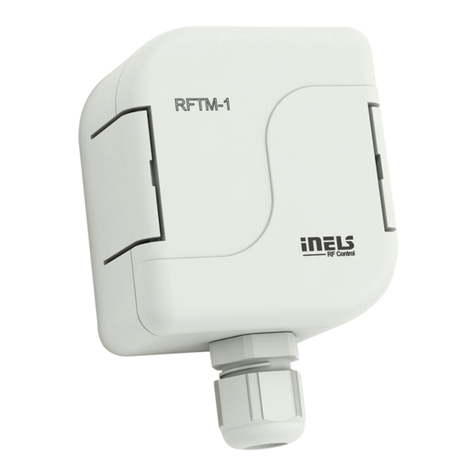
RFTM-1
Wireless pulse converter
EN
02-82/2016 Rev.0
Made in Czech Republic
SENSOR SET
Characteristics /
• The wireless pulse converter detects home energy meters (electric, water, gas) by means of sensors,
and sends them to the wireless unit RFPM-2M.
• The energy gateway RFPM-2M acts as an interface between the meter and a smartphone.
• Measured values are displayed in the application iHC-MAIRF/MIIRF, in daily, weekly or monthly
overview in graphs.
• The sensor is designed for use on existing meters and even without the impulse output“S0”(The
gauge must support scan).
• RFTM-1 transfers consumption from meters using sensors - LS (LED sensor), WS (Magnetic sensor
for meter), MS (Magnetic sensor) or by impulse output („S0“). The sensor does not effect meter
consumption, nor does it interfere with the reading measurements the meter makes.
• For each consumption meter, it is necessary to have one pulse converter RFTM-1.
• The increased IP65 protection is appropriate for mounting in risers, switchboards and other de-
manding environments.
• Battery power (1.5 V / 2x AAA - included in package) with average battery life of around 2 years
(according to the type of scan, frequency of transmissions and pulses).
• Range up to 100 m (in open space), if the signal between the controller and the user is weak, use
the signal repeater RFRP-20 or protocol component RFIO2that support this feature.
• Communication frequency with bidirectional protocol iNELS RF Control.
Radio frequency signal penetration through various construction materials /
1/3
60 - 90 % 80 - 95 % 20 - 60 % 0 - 10 % 80- 90 %
brick walls wooden structures
with plaster boards reinforced
concrete metal partitions common glass
Indication, settings, types of sensors /
battery holders / • Red LED - pulse indication
- indication of wrong communication
• Green LED - indication of setting mode
- indication of correct communication
• Button SET - long press (> 1s) - activating the Adjustment mode
- short press (< 1s) - Communications Test
• Terminal block for sensor connection
• Set the sensor type:
1 - S0: Meters with pulse output designated as „S0“ (passive contact, open collector, reed
magnetic contacts).
2 - LS: LED sensor (scans LED impulses on the meter, which indicates consumption by
flashing).
3 - MS, WS: Magnetic sensor (scans movement of the numeral, upon which a permanent
magnet is placed).
4...10 - Service
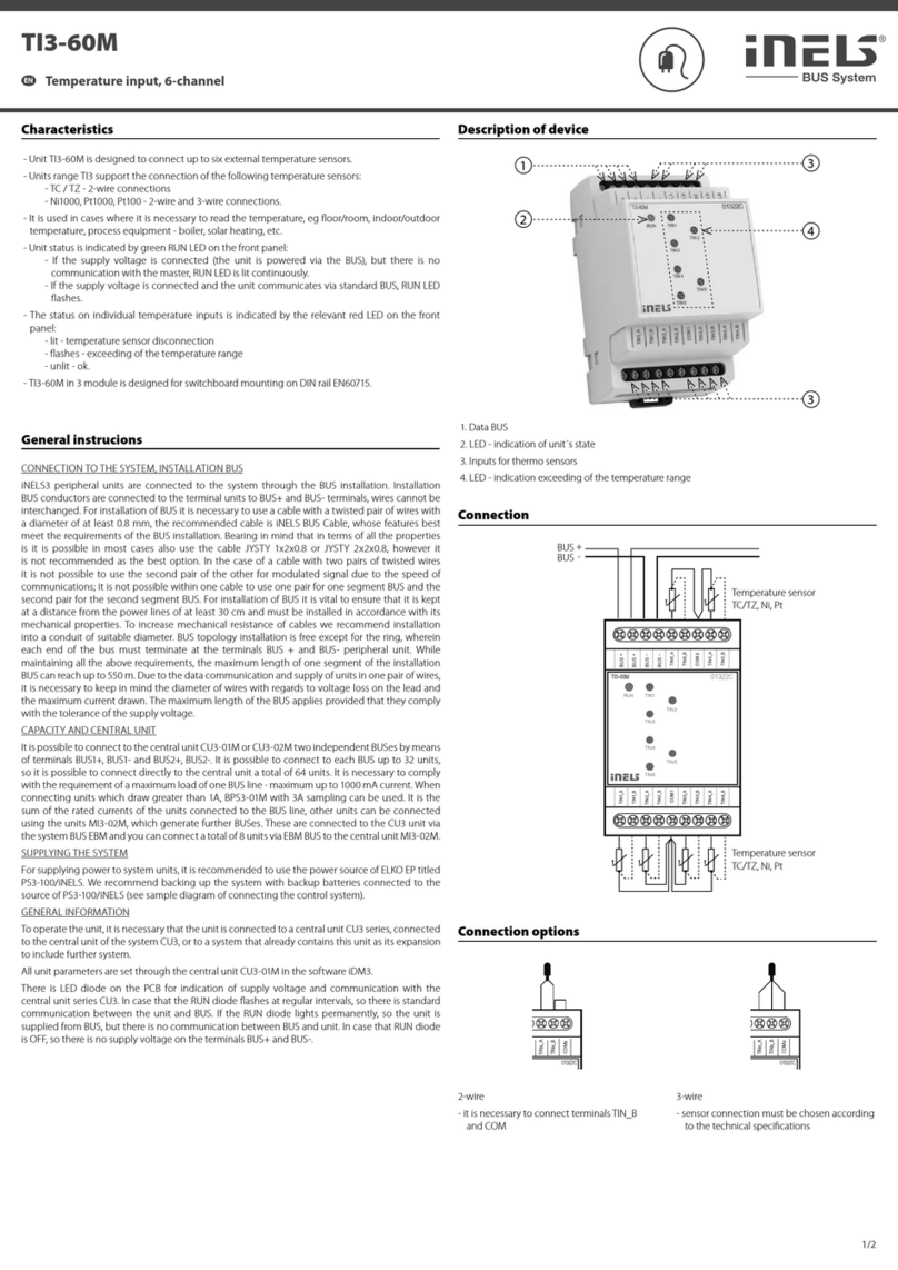
Before starting the programming / manual control, open the actua-
tor housing using a screwdriver. Indication and control units are lo-
cated inside the box.
After completing programming / manual control, snap the housing
closed again.
button /
sensor selection /
terminal blocks /
SENSOR
5 6
4 7
3 8
2 9
1 10
cable gland /
☺
☺
☺
☺

RFRP-20
☺
LED STATUS
LED SET
www.elkoep.com / www.elkoep.sk
ELKO EP, s.r.o. | Palackého 493 | 769 01 Holešov, Všetuly | Czech Republic | e-mail: [email protected] | Support: +420 778 427 366
ELKO EP SLOVAKIA, s.r.o. | Fraňa Mojtu 18, 949 01 Nitra | Telefón: +421 37 6586 731 | E-mail: [email protected]
Bezdrôtový prevodník pulzov
SK
Charakteristika
• Bezdrôtový prevodník pulzov detekuje snímače domácej energie (elektrina, voda, plyn) pomocou
senzorov a posiela ich do bezdrôtovej jednotky RFPM-2M.
• Energy brána RFPM-2M je prostredníkom medzi meradlom a chytrým telefónom.
• Namerané hodnoty sa zobrazujú v aplikácii iHC-MAIRF/MIIRF a to v dennom, týždennom či
mesačnom prehľade v grafoch.
• Snímač je určený na použitie na existujúcich meracích prístrojoch i bez impulzného výstupu„S0“
(meradlá musia snímanie podporovať).
• RFTM-1 prevádza spotrebu z meradla pomocou senzorov - LS (LED senzor), MS (Magnetic senzor),
WS (Magnetický senzor pre vodomer) alebo impulzným výstupom („S0“). Senzory neovplyvňujú
merač spotreby a nemajú vplyv na meranie sledovanej veličiny.
• Pre každé meradlo spotreby je nutné mať jeden prevodník pulzov RFTM-1.
• Zvýšené krytie IP65 je vhodné pre montáž do stúpačiek, rozvádzačov a iných náročných prostredí.
• Batériové napájanie (1.5 V / 2x AAA - súčasťou balenia) s priemernou životnosťou cca 2 roky
(podľa druhu snímania, vrátane vysielania a impulzov).
• Dosah až 100 m (na voľnom priestranstve), v prípade nedostatočného signálu medzi ovládačom
a prvkom použite opakovač signálu RFRP-20 alebo prvky s protokolom RFIO2, ktoré túto funkciu
podporujú.
• Komunikačná frekvencia s obojsmerným protokolom iNELS RF Control.
Priestup rádiofrekvenčných signálov rôznymi stavebnými materiálmi
tehlové steny drevené konštrukcie
so sadrokartónovými
doskami vystužený betón kovové prepážky bežné sklo
Indikácia, nastavenie, typy senzorov
Pred začatím programovania / manuálneho ovládania otvorte
pomocou skrutkovača kryt prvku. Indikácie a ovládacie prvky sú
umiestnené vo vnútri krabičky.
Po ukončení programovania / manuálneho ovládania kryt zacvaknite.
držiaky batérií • Červená LED - indikácia pulzov
- indikácia chybnej komunikácie
• Zelená LED - indikácia nastavovacieho režimu
- indikácia správnej komunikácie
• Tlačidlo SET - dlhé stlačenie (> 1s) - aktivácia nastavovacieho režimu
- krátke stlačenie (< 1s) - test komunikácie
• Svorkovnice pre pripojenie senzorov
• Nastavenie typu senzoru:
1 - S0: Meracie prístroje s impulzným výstupom označeným ako „S0“ (pasívny kontakt,
otvorený kolektor, jazýčkový magnetický kontakt).
2 - LS: LED senzor (sníma impulzy na meracom prístroji, ktorý blikaním LED indikuje spotrebu).
3 - MS, WS: Magnetický senzor (sníma pulz, ktorý vytvorí každým otočením magnet
umiestnený na jednotkovom ciferníku).
4...10 - Servis
tlačidlo SET
red / červená
voľba senzoru
svorkovnice
káblová prechodka
green / zelená
RFTM-1
Wireless pulse converter
EN
02-82/2016 Rev.0
Made in Czech Republic
Sensor connection /
Pull the cable end of the sen-
sor cable through the cable
gland and connect it to the
terminal box (see the individ-
ual sensor instructions for the
wiring diagram).
On the potentiometer, select
the type of connected sensor,
loosen the cable grommet.
Adjust the cable guide inside
the box and tighten the cable
gland.
3
Press SET > 1s to enter RFTM-1
into setting mode, green LED
SET flashes.
Switch on the appliance (gas
stove, faucet, kettle...) de-
pending on the type of ener-
gy being scanned (gas, water,
electricity).
Insert the batteries, observe
the polarity.
4
1 2
5 6

Sensor SET
5 6
4 7
3 8
2 9
1 10
Sensor SET
5 6
4 7
3 8
2 9
1 10
Sensor SET
5 6
4 7
3 8
2 9
1 10


Sensor SET
5 6
4 7
3 8
2 9
1 10
+
-
+
-
Press the SET < 1s button to
exit the setting mode. (After
5 minutes, the adjustment
mode ends automatically.)
Attach the sensor to the scan-
ning position. The cable must
be loose. Check the scanning
accuracy - the red LED blinks
when the pulse is detected.
Clean the sensor surface (de-
pending on the sensor type)
and attach the sensor. The red
LED blinks when the pulse is
detected. *
7 8 9
Sensor SET
5 6
4 7
3 8
2 9
1 10
+
-
+
-

Sensor SET
5 6
4 7
3 8
2 9
1 10
+
-
+
-

Pairing with RFPM-2M /
xxxxxx
address /
For pairing with RFPM-2M, the address on the side of the component is the par-
ing address. RFTM-1 can be paired with one RFPM-2M.
Press SET < 1s to test communication with paired RFPM-2M.
Success rate indication:
- Green LED blinks - the connection is successful.
- Red LED blinks - no or bad connection - relocate the RFTM-1.
Position the RFTM-1 within the range of the gauging gauge and fasten with
suitable bonding material according to the type of substrate (gluing, round
head screws - maximum head diameter 8 mm, maximum thread diameter 4 mm,
minimum length 30 mm).
Because of the significantly reduced throughput of the RF signal with metal
partitions, it is not recommended to install it inside metal switchboards.
Assembly /
2/3
Sensor SET
5 6
4 7
3 8
2 9
1 10
* If the sensor type is incorrectly adjusted, adjust the sensor type on the rotary switch and press
the SET < 1s key.
www.elkoep.com / www.elkoep.sk
ELKO EP, s.r.o. | Palackého 493 | 769 01 Holešov, Všetuly | Czech Republic | e-mail: [email protected] | Support: +420 778 427 366
ELKO EP SLOVAKIA, s.r.o. | Fraňa Mojtu 18, 949 01 Nitra | Telefón: +421 37 6586 731 | E-mail: [email protected]
Bezdrôtový prevodník pulzov
SK
Pripojenie senzoru
Na potenciometri zvoľte typ
pripojeného snímača, uvoľnite
káblovú prechodku. Vytiahnite koniec káblu s
dutinkami zvoleného senzoru
cez káblovú prechodku
a zapojte do svorkovnice
(schéma zapojenia viď návod
jednotlivých senzorov).
Upravte vedenie káblu vo
vnútri krabičky a utiahnite
káblovú prechodku.
Vložte batérie, pozor na po-
latitu.
Podľa druhu snímanej energie
(plyn, voda, elektrina) zapnite
spotrebič (plynový sporák,
vodovodný kohútik, varná
kanvica...).
Očistite snímaciu plochu
meracieho prístroja (podľa
typu senzoru) a priložte senzor.
Pri zaznamenaní impulzu
preblikne červená LED. *
Pripevnite senzor na miesto sní-
mania. Kábel musí byť vedený
voľne. Prekontrolujte správnosť
snímania - pri zaznamenaní
impulzu preblikne červená LED.
Stlačením tlačidla SET < 1s
ukončíte nastavovací režim.
(Po 5 minútach sa nastavovací
režim ukončí automaticky.)
Stlačením tlačidla SET > 1s
uvediete RFTM-1 do nastavo-
vacieho režimu, zelená LED SET
začne blikať.
Spárovanie s RFPM-2M
adresa
Pre spárovanie s RFPM-2M slúži adresa, uvedená na bočnej strane prvku. RFTM-1
môže byť spárovaný s jedným RFPM-2M.
Stlačením tlačidla SET < 1s otestujte komunikáciu so spárovaným RFPM-2M.
Indikácia úspešnosti spojenia:
- Preblikne zelená LED - spojenie je úspešné.
- Preblikne červená LED - žiadne alebo zlé spojenie - premiestnite RFTM-1.
Výrobok RFTM-1 umiestnite v dosahu snímaného meracieho prístroja a upevnite
vhodným spojovacím materiálom podľa typu podkladu (lepenie, skrutky s
poľgulatou hlavou - max. priemer hlavy 8 mm, max. priemer závitu 4 mm, min.
dĺžka 30 mm).
Z dôvodu výrazne zníženej priechodnosti RF signálu kovovými prepážkami
neodporúčame inštalovať dovnútra kovových rozvádzačov.
Montáž
* Pri chybnom nastavení typu senzoru upravte typ senzoru na otočnom prepínači a stlačte
tlačidlo SET < 1s.
RFTM-1
Wireless pulse converter
EN
02-82/2016 Rev.0
Made in Czech Republic
Sensor SET
5 6
4 7
3 8
2 9
1 10
+
-
+
-
Sensor SET
5 6
4 7
3 8
2 9
1 10
3/3
1
Replacement of a battery /
2
Open the actuator housing
using a screwdriver. Remove the original batteries
and insert new batteries into
the battery holder (do not use
new and used batteries to-
gether). Observe the polarity.
Snap on the cover.
3
+
-
+
-
Safe handling /
When handling a device unboxed it is important to avoid contact with liquids. Avoid contact
with the components of the device.
Technical parameters /
Sensor SET
5 6
4 7
3 8
2 9
1 10
+
-
+
-
Instruction manual is designated for mounting and also for user of the device. It is always a part of its packing.
Installation and connection can be carried out only by a person with adequate professional qualification upon un-
derstanding this instruction manual and functions of the device, and while observing all valid regulations. Trouble-
free function of the device also depends on transportation, storing and handling. In case you notice any sign of
damage, deformation, malfunction or missing part, do not install this device and return it to its seller. It is necessary
to treat this product and its parts as electronic waste after its lifetime is terminated. Before starting installation, make
sure that all wires, connected parts or terminals are de-energized. While mounting and servicing observe safety
regulations, norms, directives and professional, and export regulations for working with electrical devices. Do not
touch parts of the device that are energized - life threat. Due to transmissivity of RF signal, observe correct location
of RF components in a building where the installation is taking place. RF Control is designated only for mounting in
interiors. The must not be installed into metal switchboards and into plastic switchboards with metal door - trans-
missivity of RF signal is then impossible. RF Control is not recommended for pulleys etc. - radiofrequency signal can
be shielded by an obstruction, interfered, battery of the transceiver can get flat etc. and thus disable remote control.
Warning
* Pay attention to the operating tempera-
ture of batteries.
Attention:
When you instal iNELS RF Control system,
you have to keep minimal distance 1 cm
between each units.
Between the individual commands must
be an interval of at least 1s.
Power supply
Battery Life:
Indication
Setting mode:
Communications Test -RF STATUS:
Normal operation:
Control
Manual control:
Sensor Selection:
Supported sensors:
(not included in the package)
Output
Sending RF communication packet:
Rangein free space:
Other data
Working temperature:
Storagetemperature:
Operating position:
Protection:
Cross-section of connecting wires:
Dimension:
Weight:
www.elkoep.com / www.elkoep.sk
ELKO EP, s.r.o. | Palackého 493 | 769 01 Holešov, Všetuly | Czech Republic | e-mail: [email protected] | Support: +420 778 427 366
ELKO EP SLOVAKIA, s.r.o. | Fraňa Mojtu 18, 949 01 Nitra | Telefón: +421 37 6586 731 | E-mail: [email protected]
Bezdrôtový prevodník pulzov
SK
Výmena batérie
Vyberte pôvodné batérie a do
držiaka batérií zasuňte batérie
nové (nikdy nekombinujte
starú a novú batériu). Pozor na
polaritu.
Zacvaknite kryt.
Bezpečná manipulácia s prístrojom
Pri manipulácii s prístrojom bez krabičky je dôležité zabrániť kontaktu s tekutinami. Nedotýkajte
sa súčiastok na prístroji.
Technické parametre
2x 1.5Vbaterry / batéria AAA
Appr. 2years, (depending on the type of sensor, frequency of transmissions and pulses) /
cca. 2roky (podľadruhu snímača, vrátane vysielania aimpulzov)
green LED ashes -active / zelená LEDbliká -aktívny
red LED-blinks when the impulse is registered by the sensor /
červená LED-preblikne pri zaregistrovaní impulzu senzorom
green LED-communication OK/ zelená LED-komunikácia OK
red LED-communication ERR / červená LED-komunikácia ERR
no indication / bez indikácie
button SET / tlačidloSET
rotary switch / otočným prepínačom
LS (LEDsensor / senzor)
MS,WS (magnetic sensor / magnetický senzor)
S0(contact, open collector, reed magnetic contacts) /
kontakt, otvorený kolektor, jazýčkový magnetický kontakt)
866 MHz, 868 MHz, 916 MHz
up to / až 100 m
-20.. +50 °C*
-30.. +70°C
any / ľubovolná
IP65
max.0.5 -1mm2
72x 62 x 34 mm
104 g
Napájanie:
Životnosť batérie:
Indikácia
Nastavovací režim:
Test komunikácie -RF STATUS:
Bežná prevádzka:
Ovládanie
Manuálne ovládanie:
Voľba senzoru:
Podporované senzory:
(nie sú súčasťou balenia)
Výstup
Odosielanie komunik. RF paketu:
Dosah na voľnom priestranstve:
Ďalšie údaje
Pracovná teplota:
Skladovacia teplota:
Pracovná poloha:
Krytie:
Prierez pripoj.vodičov:
Rozmer:
Hmotnosť:
* Dbajte na pracovnú teplotu batérií.
Upozornenie:
Pri inštalácii systému iNELS RF Control musí
byť dodržaná minimálna vzdialenosť medzi
jednotlivými prvkami 1 cm.
Medzi jednotlivými povelmi musí byť
rozostup minimálne 1s.
Návod na použitie je určený pre montáž a pre užívateľa zariadenia. Návod je vždy súčasťou balenia. Inštaláciu a
pripojenie môžu vykonávať iba pracovníci s príslušnou odbornou kvalifikáciou, pri dodržaní všetkých platných
predpisov, ktorí sa dokonale zoznámili s týmto návodom a funkciou prvku. Bezproblémová funkcia prvku je tiež
závislá na predchádzajúcom spôsobe transportu, skladovania a zaobchádzania. Pokiaľ objavíte akékoľvek známky
poškodenia, deformácie, nefunkčnosti alebo chýbajúci diel tento prvok neinštalujte a reklamujte ho u predajcu. S
prvkom či jeho časťami sa musí po ukončení životnosti zaobchádzať ako s elektronickým odpadom. Pred začatím
inštalácie sa uistite, že všetky vodiče, pripojené diely či svorky sú bez napätia. Pri montáži a údržbe je nutné
dodržiavať bezpečnostné predpisy, normy, smernice a odborné ustanovenia pre prácu s elektrickými zariadeniami.
Nedotýkajte sa častí prvku, ktoré sú pod napätím - nebezpečenstvo ohrozenia života. Z dôvodu priepustnosti RF
signálu dbajte na správne umiestnenie RF prvkov v budove, kde sa bude inštalácia prevádzať. RF Control je určený
iba pre montáž do vnútorných priestorov. Prvky nie sú určené pre inštaláciu do vonkajších a vlhkých priestorov,
nesmú byť inštalované do kovových rozvádzačov a do plastových rozvádzačov s kovovými dverami - znemožní
sa tak priepustnosť rádiofrekvenčného signálu. RF Control sa neodporúča pre ovládanie prístrojov zaisťujúcich
životné funkcie alebo pre ovládanie rizikových zariadení ako sú napr. čerpadlá, el. ohrievače bez termostatu, výťahy,
kladkostroje a pod. - rádiofrekvenčný prenos môže byť tienený prekážkou, rušený, batéria vysielača môže byť vybitá
a pod., a tým môže byť diaľkové ovládanie znemožnené.
Varovanie
Pomocou skrutkovača otvorte
kryt prvku.
Other iNels Media Converter manuals

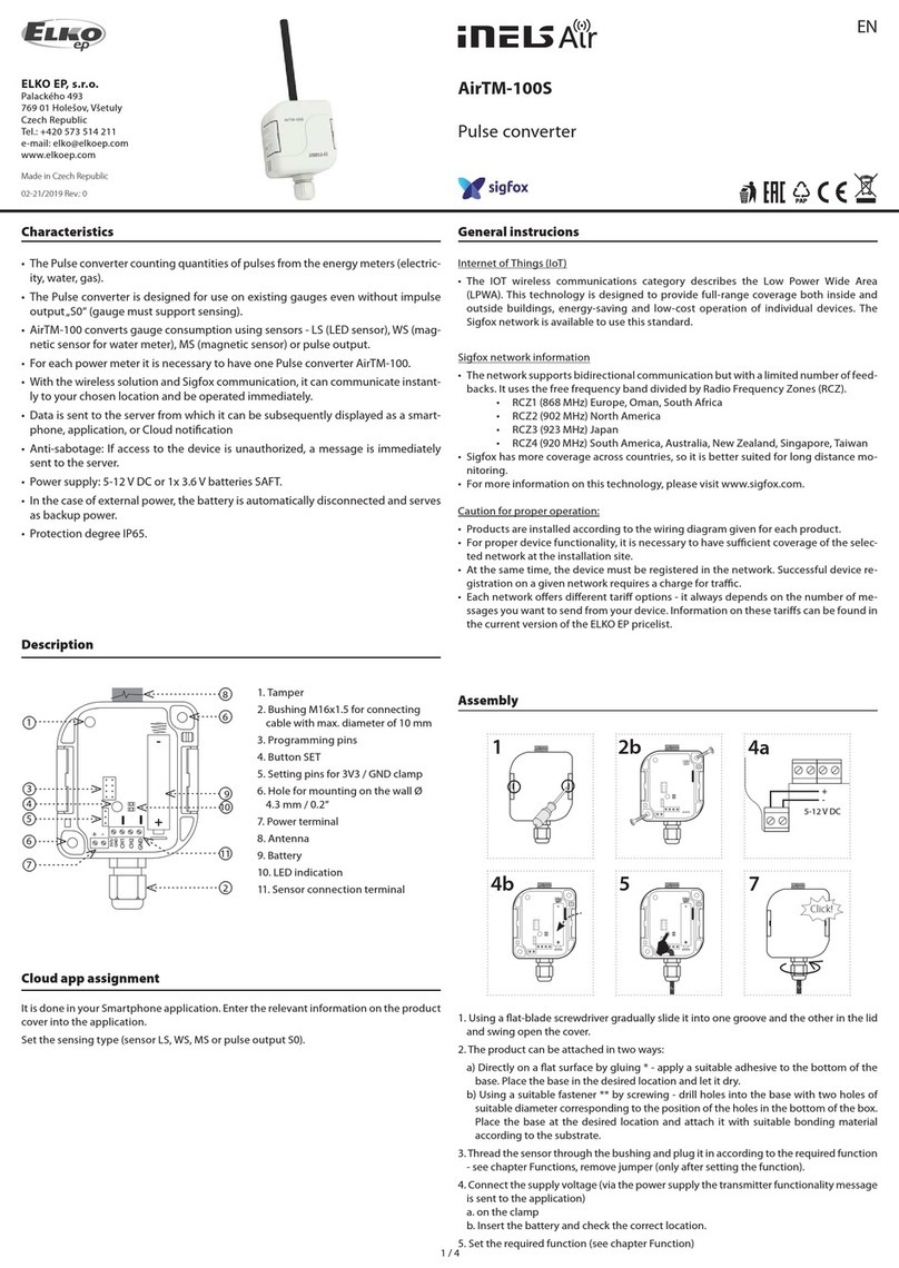
iNels Elko AirTM-100S User manual

iNels

iNels Elko AirTM-100S User manual

iNels RFSG-1M User manual

iNels

iNels RFSG-1M User manual

iNels RFSG-1M User manual

iNels

iNels RFSG-1M User manual

iNels ADC3-60M User manual

iNels

iNels ADC3-60M User manual

iNels RFSG-1M User manual

iNels

iNels RFSG-1M User manual

iNels RFIM-20B User manual

iNels

iNels RFIM-20B User manual

iNels RFSG-1M User manual

iNels

iNels RFSG-1M User manual

iNels DAC2-04M User manual

iNels

iNels DAC2-04M User manual

iNels TI3-60M User manual

iNels

iNels TI3-60M User manual

iNels RFSG-1M User manual

iNels

iNels RFSG-1M User manual

iNels Elko AirTM-100NB User manual

iNels

iNels Elko AirTM-100NB User manual

iNels Elko AirTM-100L User manual

iNels

iNels Elko AirTM-100L User manual

iNels ADC3-60M User manual

iNels

iNels ADC3-60M User manual

iNels DAC3-04B User manual

iNels

iNels DAC3-04B User manual

iNels RFSG-1M User manual

iNels

iNels RFSG-1M User manual

iNels RFTM-1 User manual

iNels

iNels RFTM-1 User manual

Popular Media Converter manuals by other brands

Cross Technologies 2099-2424 instruction manual

Cross Technologies

Cross Technologies 2099-2424 instruction manual

Ocean Matrix OMX HDMI SDI user guide

Ocean Matrix

Ocean Matrix OMX HDMI SDI user guide

Texas Instruments TPS6110XEVM-216 user guide

Texas Instruments

Texas Instruments TPS6110XEVM-216 user guide

Sunix FTL-1218H-G Series Quick installation guide

Sunix

Sunix FTL-1218H-G Series Quick installation guide

ICP ZT-2550 user manual

ICP

ICP ZT-2550 user manual

Monacor UA-960 instruction manual

Monacor

Monacor UA-960 instruction manual

CYP DCT-15 Operation manual

CYP

CYP DCT-15 Operation manual

Xylem YSI WaterLOG H-3301 owner's manual

Xylem

Xylem YSI WaterLOG H-3301 owner's manual

Sennheiser MobileConnect quick guide

Sennheiser

Sennheiser MobileConnect quick guide

Sonnet Hermes owner's manual

Sonnet

Sonnet Hermes owner's manual

Advantech SSPBM-K80-BTE Installation and operating manual

Advantech

Advantech SSPBM-K80-BTE Installation and operating manual

Clever Little Box LCU-1A User instructions

Clever Little Box

Clever Little Box LCU-1A User instructions

Kingrex UD384 user manual

Kingrex

Kingrex UD384 user manual

Synectics e1600 user manual

Synectics

Synectics e1600 user manual

CYP CH-301TX Operation manual

CYP

CYP CH-301TX Operation manual

Collingwood Lighting 5055351501473 Wiring instructions

Collingwood Lighting

Collingwood Lighting 5055351501473 Wiring instructions

American DJ Multi-Data/PAK User instructions

American DJ

American DJ Multi-Data/PAK User instructions

Absolute Process Instruments DuoPak APD 2010 manual

Absolute Process Instruments

Absolute Process Instruments DuoPak APD 2010 manual

manuals.online logo
manuals.online logoBrands
  • About & Mission
  • Contact us
  • Privacy Policy
  • Terms and Conditions

Copyright 2025 Manuals.Online. All Rights Reserved.