2
TLP Pro 1225MG and TLP Pro 1525MG • Setup Guide
Mounting
ATTENTION:
• Do not install the TLP Pro 1225MG, or TLP Pro 1525MG in a re resistant rated wall or partition assembly.
• Ne pas installer le TLP Pro 1225MG ou le TLP Pro 1525MG dans un mur résistant au feu ou une cloison.
• All structural steps and electrical installation must be performed by qualied personnel in accordance with local and
national building codes and electrical codes.
• Toute étape structurelle et installation électrique, doit être effectuée par un personnel qualié, conformément aux codes
du bâtiment, aux codes incendie et sécurité, et aux codes électriques, locaux et nationaux.
Wall Mounting
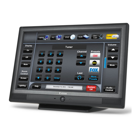
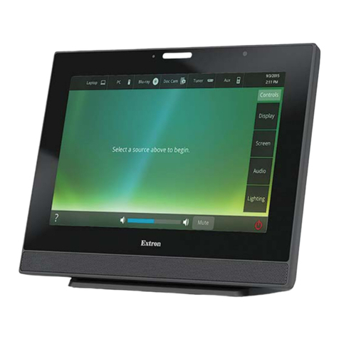
The touchpanels can be wall mounted, using the provided hardware. Where local codes require a rear metal enclosure, either model
can be mounted using the Extron BB 700M (not provided). Figure 1 shows the TLP Pro 1525MG. Mount the TLP Pro 1225MG in the
same way.
With a wall box
Some local building codes require the touchpanel to be mounted in a wall box such as the Extron BB 700M. This installation
procedure is described below.
1. Cut a hole in the drywall, 9.55 inches (24.26 cm) wide x 6.55 inches (16.64 cm) high, and install the BB 700M ( see gure 1, 1),
as described in the BB 700M Installation Guide (see www.extron.com).
2. Place the metal mounting plate against the wall, mark the
four mounting holes, and drill four pilot holes (2).
Install BB 700M (optional).
TLP Pro 1525MG
Back View
Hold the touchpanel at a slight angle.
Mount the touchpanel over the two
hooks on the mounting plate.
Add the mounting plate. Align with
the wall box and mark holes for screws.
Secure the mounting plate
to the wall with screws (4).
Place the provided mounting screws (2)
with washers in the mounting screw slot
in the touchpanel.
6
5
3
1
2
4
7
Secure the touchpanel by tightening the
mounting screws against the base of the
mounting plate.
3. Secure the mounting plate with four #10
screws (3).
4. Run and connect cables to the back of the
touchpanel (4, and see Rear Panel
Features on page 4).
5. Insert the two provided Phillips pan
head #6-32 x ¾ inch length screws
with washers in the mounting screw
slot (5, see Figure 1, Back View
inset). Leave a gap for the ange at the
bottom of the mounting plate to t into.
6. Hold the touchpanel at a slight angle
and lower the notches at the top of the
back panel (6) over the hooks of the
mounting plate.
7. Swing the bottom of the touchpanel
inwards so that it lies at against
the mounting plate with the ange
at the bottom of the mounting plate
sitting in a groove in the bottom of the
touchpanel.
8. Secure the touchpanel to the mounting
plate with the mounting screws (7).
Without a wall box
If the wall box is not required by local building
codes, you can mount the touchpanel directly into
drywall.
1. Download the cut-out template for your touchpanel
from www.extron.com. Print it at 100% (no scaling).
2. Use the template to mark the wall, cut the hole, and drill
the four pilot holes.
The size of the cut-out hole is 9.25 inches (23.50 cm) wide x
6.25 inches (15.88 cm) high.
3. Secure the mounting plate and complete the installation, as
described in steps 3 through 8 above.
steps 3 through 8
Figure 1. TLP Pro 1525MG Mounting
