extronics iTAG X30 User manual

Operating Manual
iTAG X30

2
Document Number X124749(2) (See DDM for the latest Version)
For warranty information, refer to Terms and Conditions at http://www.extronics.com
©2021 Extronics Limited. This document is Copyright Extronics limited.
Extronics reserve the right to change this manual and its contents without notice, the latest
version applies.

3
Contents
Contents
Introduction.......................................................................................................... 5
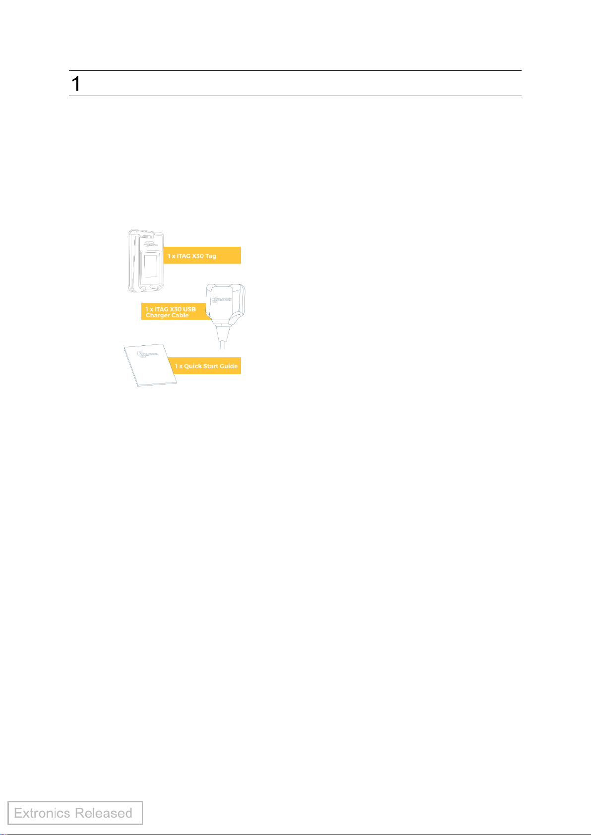
1.1 What is inside the box? ................................................................................. 5
1.2 Pre-requisites ................................................................................................ 5
1.3 Reference documentation ............................................................................. 5
Safety Information ............................................................................................... 6
2.1 Storage of this manual................................................................................... 6
2.1 Special conditions for safe use –ATEX IECEx ............................................ 6
2.2 Warnings ...................................................................................................... 6
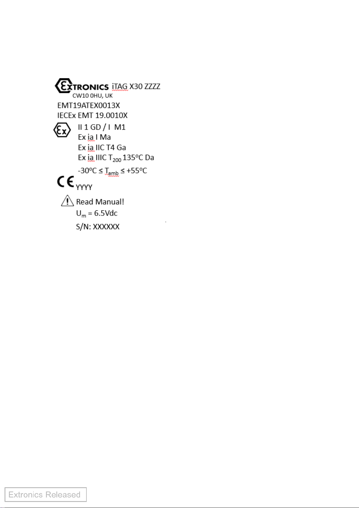
2.3 Marking information....................................................................................... 7
2.3.1 iTAG X30AI............................................................................................. 7
iTAG X30 Features.............................................................................................. 8
3.1 Emergency call button................................................................................... 8
3.2 Visual, audible and tactile indication.............................................................. 8
3.3 Wi-Fi security................................................................................................. 8
3.4 Beaconing ..................................................................................................... 8
3.5 Wi-Fi / GPS ................................................................................................... 8
3.6 Wi-Fi range.................................................................................................... 8
3.7 LF radio......................................................................................................... 8
3.8 Over-The-Air updates.................................................................................... 8
3.9 Battery and battery life................................................................................... 9
3.10 Mounting .................................................................................................... 9
3.11 Simple configuration................................................................................... 9
3.12 Motion sensor............................................................................................. 9
3.13 Integrated access control........................................................................... 9
3.14 Rugged performance.................................................................................. 9
iTAG X30 Usage Instructions............................................................................ 10
4.1 Before using the iTAG X30.......................................................................... 10
4.2 Configuring the iTAG X30............................................................................ 10
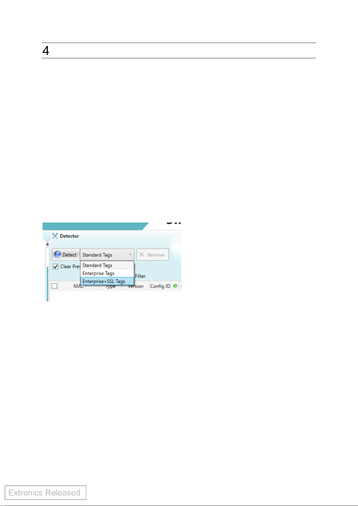
4.2.1 To detect iTAG X30 .............................................................................. 10
4.2.2 Detected iTAG X30 list.......................................................................... 10
4.2.3 Activating the iTAG X30........................................................................ 11
4.2.4 How to configure................................................................................... 12
4.2.5 Applying the transmission channels...................................................... 13
4.2.6 Applying the configuration ID................................................................ 13
4.2.7 Available configurations........................................................................ 14
4.2.8 Applying the wireless settings............................................................... 15
4.3 LED and audio indications........................................................................... 17
4.4 Wearing the tag........................................................................................... 18
4.5 Battery......................................................................................................... 18
4.5.1 Battery levels and charging indications................................................. 18
4.5.2 Charging the battery ............................................................................. 19
4.5.3 Variances in battery life......................................................................... 19
4.6 Over the Air (OTA) update........................................................................... 20
4.7 Inserting the access control / photo ID card ................................................ 21
4.8 Transport..................................................................................................... 22
4.9 Authorised persons...................................................................................... 22

4
4.10 Cleaning and maintenance....................................................................... 22
4.10.1 Assembly and disassembly ............................................................... 23
4.10.2 Aggressive substances...................................................................... 23
4.11 Exposure to external stresses.................................................................. 23
Variants............................................................................................................. 24
EU Declaration of Conformity............................................................................ 25
Manufacturer..................................................................................................... 28
Radio Equipment –FCC and ISED Warning Statement.................................... 29

5
Introduction
The iTAG X30 worker location tag with hybrid technology, allows for the accurate
location of workers in hazardous and non-hazardous areas. The iTAG X30 provides
audible, visual and tactile alerts and works with Stanley MobileView software to provide
real-time alerting and reporting for worker location solutions.
1.1 What is inside the box?
1.2 Pre-requisites
Refer to iTAG X30 Compatibility Matrix (X124937) for compatible software required to
use the iTAG X30.
1.3 Reference documentation
•ELS Deployment Guide (X126582)
•iTAG X30 Datasheet
•MobileView Administrator Guide from 5.4 MR1 and above
•MobileView 5.4 MR1 Deployment & Configuration Guide
•AeroScout Location Engine 5.4 MR1 Deployment & Configuration Guide
•AeroScout Tag Manager BD User Guide

6
Safety Information
2.1 Storage of this manual
Keep this user manual safe and in the vicinity of the product. All persons required to
work with the product should be advised on where the manual is stored.
2.1 Special conditions for safe use – ATEX IECEx
•iTAG X30 must only be charged in a safe area.
•iTAG X30 must only be charged from a supply meeting the following requirements:
oA SELV (<15W) or PELV system, or
oa safety isolating transformer complying with the requirements of IEC 61558-2-6,
or technically equivalent standard, or
oconnected to apparatus complying with the IEC 60950 series, IEC 61010-1, or a
technically equivalent standard, or
ofed directly from cells or batteries.
•iTAG X30 charger input Um= 6.5Vdc.
•Battery cells must not be replaced in a hazardous area.
2.2 Warnings
Warning! The iTAG X30 should only be cleaned with a damp cloth.
Warning! Do not open the iTAG X30. There are no user-serviceable parts inside.
Warning! Any repairs or replacement of parts MUST be performed by the
manufacturer or its nominated sub-contractor or agent.
Warning! This product can be delivered in a number of different variants. Each
variant has restrictions on where it can be used. Please read the
information on the product label fully and ensure that your iTAG X30 is
suitable for the hazardous area in which it is to be used.
Warning! Before setting the units to work read the technical documentation
carefully.
Warning! The iTAG X30 contains a lithium ion battery. Do not force open, heat
excessively or dispose of in fire.

7
2.3 Marking information
2.3.1 iTAG X30AI
Where:
•YYYY is the Notified Body for production
•XXXXXX is the serial number
•ZZZZ is a code to identify model variants
Exact layout of markings may differ from that shown.

8
iTAG X30 Features
3.1 Emergency call button
The iTAG X30 features a call button which can be activated in the case of an
emergency, which triggers an event in MobileView to show the location of the worker
in need of assistance.
3.2 Visual, audible and tactile indication
The iTAG X30 features multiple LEDs to indicate to the worker that it is running, the
call button has been activated and when it has a low battery. Tactile and audible
indications occur to inform the wearer that the call button has been activated.
3.3 Wi-Fi security
The iTAG X30 supports WPA2-PSK Wi-Fi security protocol used during Over-The-Air
updates.
3.4 Beaconing
The tag utilises lightweight beaconing communication.
3.5 Wi-Fi / GPS
The iTAG X30 features hybrid technology which includes Wi-Fi and GPS to accurately
locate workers in all areas of the site whether there is a dense Wi-Fi infrastructure or
not.
3.6 Wi-Fi range
Outdoor –Up to 200m (line of sight to an Access Point)
Indoor –Up to 80m (infrastructure dependant)
3.7 LF radio
The iTAG X30 sends out specific location reports upon arrival at a chokepoint or
gateway where an LF exciter is positioned. The iTAG X30’s behaviour can be
automatically modified whilst in certain areas after passing through a chokepoint such
as a doorway or gate.
3.8 Over-The-Air updates
The tag has firmware Over-The-Air (OTA) update capability which can be used when
new functionality becomes available. This eliminates the need to return the iTAG X30
to the factory to enable new features.

9
3.9 Battery and battery life
The iTAG X30 has a long lasting rechargeable lithium ion battery.
3.10 Mounting
The iTAG X30 comes complete with a stainless steel buckle clip which can clip to PPE
or be used with a lanyard.
3.11 Simple configuration
The iTAG X30 firmware contains predefined configurations, which can be activated
quickly and easily using the TED and Tag Manager BD (TMBD).
3.12 Motion sensor
The iTAG X30 contains an on-board motion sensor. When the iTAG X30 is configured
to a profile which utilises the motion sensor it will enable different transmission intervals
whether it is stationary or in motion, reducing unnecessary network traffic and
conserving the battery.
3.13 Integrated access control
The iTAG X30 minimises the number of ancillary products being carried by using
integrated access control to gain site access. This easily identifies workers using the
Photo ID which is visible on the front.
3.14 Rugged performance
The iTAG X30’s enclosure has been designed for durability with ratings of IP65 and
IP67 to ensure complete confidence in the product when in harsh environments.

10
iTAG X30 Usage Instructions
4.1 Before using the iTAG X30
Please check for damage to the iTAG X30 and Charging Cable prior to use.
Check firmware is to the latest version and update if required.
4.2 Configuring the iTAG X30
TMBD is used to configure the iTAG X30. Refer to Tag Manager BD User Guide for
more detailed instructions.
4.2.1 To detect iTAG X30
1. Arrange the iTAG X30 around the TED device.
2. Confirm the TMBD application is running.
3. Connect the TED to the PC and select the connection in the TMBD menu.
4. To detect iTAG X30’s select Enterprise+SSL Tags, Figure 1.
Figure 1.
TMBD detects the available iTAG X30s.
4.2.2 Detected iTAG X30 list
Detected iTAG X30s are listed in the Detected Tags window, Figure 2. The detected
tag count is displayed at the bottom of the window. An image of the iTAG X30 is
displayed when placing the mouse over the detected tag.

11
Figure 2.
4.2.3 Activating the iTAG X30
iTAG X30s leave the factory in a dormant mode for shipping purposes. Dormant iTAG
X30s only react to two commands: Activate and Deactivate. iTAG X30 must be
activated before configuring and use. Single or multiple iTAG X30s can be activated
simultaneously.
1. To Activate the iTAG X30(s)
Confirm the iTAG X30 is detected. From the Detected Tags list, right click on the iTAG
X30 and select Activate. The tag colour indicator changes to green (Activated Tag),
Figure 3. The iTAG X30’s LED will flash green to indicate communication.
Figure 3.
OR to activate multiple tags:
Confirm the tags are detected.
From the Detected Tags list, select the iTAG X30s by checking their selection boxes
(or check the box in the column header to select them all). Under the selection Tag
Configuration, select Activate and check the Tag state box, Figure 4.
Figure 4.
2. Click Apply. The Applying Configuration window opens, Figure 5.

12
Figure 5.
The tag colour indicator changes to green (Activated Tag).
3. Click Finish, Figure 5.
4.2.4 How to configure
The iTAG X30 can be configured using the TMBD application.
The TMBD application allows you to configure the following tag parameters (if not
already factory set) according to the site’s infrastructure and use case. More
information can be found in the Tag Manager BD User Guide.
Transmission and Wireless, Figure 6.
•Transmission Channels
•IP Settings (Static IP/DHCP)
•Application servers
•Wi-Fi Security Settings - WPA2-PSK

13
Figure 6.
4.2.5 Applying the transmission channels
1. From the Detected Tags list check the iTAG X30s to configure.
2. Click the Transmission arrow . The transmission section opens, Figure 7.
3. Under the Channels section, select the transmission channel(s).
4. Click on the Data Frame Format drop down menu and select data frame format.
The Data Frame Format specifies the format of the tag location messages sent to
destination address. The data frame format configured in the tags should match the
data frame format of the access points. iTAG X30 tags support CCX, IBSS and WDS
data frame formats and combinations.
Figure 7.
4.2.6 Applying the configuration ID
Select the configuration ID which best suits your application, Figure 8.

14
Figure 8.
4.2.7 Available configurations
The iTAG X30 firmware contains predefined configurations. These configurations
define the tag type and beacon rate behaviour. Each configuration has a unique ID
number called a “Static Configuration” which cannot be edited. Only one configuration
can be selected and used per iTAG X30.
The following table shows the available configurations:
Static
Config
ID
Tag type
Beacon rate
Motion
enabled
Transmission
SD&CT
182
iTAG X30
5 Seconds
No
Unidirectional
No
183
iTAG X30
15 Seconds
No
Unidirectional
No
184
iTAG X30
1 Minute / 15 seconds motion
Yes
Unidirectional
No
185
iTAG X30
3 Minute / 5 seconds motion
Yes
Unidirectional
No
186
iTAG X30
3 Minute / 15 seconds motion
Yes
Unidirectional
No
187
iTAG X30
3 Minute / 30 seconds motion
Yes
Unidirectional
No
188
iTAG X30
5 Minute / 30 seconds motion
Yes
Unidirectional
No
210
iTAG X30
5 Seconds
No
Unidirectional
Yes
211
iTAG X30
15 Seconds
No
Unidirectional
Yes
212
iTAG X30
1 Minute / 15 seconds motion
Yes
Unidirectional
Yes
213
iTAG X30
3 Minute / 5 seconds motion
Yes
Unidirectional
Yes
214
iTAG X30
3 Minute / 15 seconds motion
Yes
Unidirectional
Yes
215
iTAG X30
3 Minute / 30 seconds motion
Yes
Unidirectional
Yes
216
iTAG X30
5 Minute / 30 seconds motion
Yes
Unidirectional
Yes
Note: SD&CT –Social Distancing and Contact Tracing

15
4.2.8 Applying the wireless settings
1. Click the Wireless . The Wireless section opens, Figure 9.
2. Select the tags IP type Static or Obtain from DHCP.
3. If you select Static, enter the relevant information in the Static IP box.
4. If you select Obtain from DHCP, an IP address is automatically assigned when a
bidirectional communication session begins. This IP address is “released” once the
bidirectional session ends. Additionally you can enter in the Automatic IP
Renewal, in hours.
Figure 9.
5. Enter the details for the Application Servers (Tag controller IP address), Figure
10. This is the address which is used by the tag to obtain firmware OTA updates
and needs to match the settings in the Extronics Location Selector (ELS). If
needed, click on the plus button to add another server IP.
Figure 10.
6. Under the Wi-Fi section, perform the following:
Enter in the networks SSID name (Extronics_OTA is the default name), Figure 11.
Select the Authentication Method:
a. WPA2-PSK (Requires a key).
b. 802.1X (Requires User Name/ Domain name and Password). Future
functionality.
Optional: Click on the plus (+) button to add an additional SSID. If the first SSID
connection fails, the tag will try the next SSID connection. At least one of the total of
four connections needs to be set.

16
WPA2-PSK: Key
Figure 11.
To complete the configuration click Apply, Figure 12.
Figure 12.

17
The Applying Configuration window opens, Figure 13.
Figure 13.
Click Finish.
4.3 LED and audio indications
The iTAG X30 has multi-colour LEDs on the top and front. Indications are shown in
the following table:
Indication
LED colour
LED
position
Sound
Vibrate
Tag on
Green Flashing
Top
N/A
N/A
Low battery
Red Flashing
Top
N/A
N/A
Critical battery
Red Solid
Top
N/A
N/A
Call button activated
Red Solid
Top and
Front
Yes
Yes
Error
Rapid Orange Flashing
Top
N/A
N/A

18
4.4 Wearing the tag
The iTAG X30 includes a versatile buckle clip, Figure 14. Ensure the iTAG X30 is
worn in an upright position. For best results wear the tag as high up your body as
possible.
Figure 14.
The iTAG X30 can be:
➢clipped to your pocket.
➢clipped to your epaulette.
➢clipped to your chest pocket.
The iTAG X30 has successfully been tested to EN 62311:2008 Section 8.3 Human
Exposure Evaluation.
4.5 Battery
The iTAG X30 has a non-replaceable rechargeable Lithium ion battery and is charged
using the Charging Cable included. Battery life depends on the configuration and use
case.
4.5.1 Battery levels and charging indications
The iTAG X30 has the following 3 battery levels that are shown in MobileView:
•High –Indicates the tag has more than 75%.
•Medium –Indicates the tag has between 75% and 30%.
•Low –Indicates the tag has less than 30%.
Indication
LED Colour
LED position
Normal operation –high and medium battery
Green flashing
Top
Low battery
Red Flashing
Top
Reserve battery
Red on
Top
Battery charging
Red Slow Flash
Top
Battery fully charged
Green on
Top
It is recommended to charge the tag daily.

19
4.5.2 Charging the battery
The iTAG X30 is charged using the USB Charging Cable provided. It is attached and
detached from the rear of the tag, Figure 15.
Figure 15.
The charger input conditions listed in the Special Conditions of Safe Use must be
observed. Charging is only permitted between 0oC and 45oC. When connecting to a
USB power supply, ensure the supply is rated less than 100W.
Warning! If the photo ID cover screw is backed out it can cause the charger to get
stuck in the charged position.
4.5.3 Variances in battery life
Variances in battery life are based on usage. Actual results may vary due to the
following:
•LF exciter usage.
•Changes in tag usage.
•Time in storage before use.
•Changes in transmission interval.
•Temperature.
•Motion.
•Indoor/Outdoor applications.
•Time to receive firm GPS co-ordinates.
The firmware endeavours to optimise battery life, using various techniques –motion
detection for example. If the iTAG X30 is being worn in a vehicle motion will be
detected.

20
4.6 Over the Air (OTA) update
When new firmware becomes available the iTAG X30’s firmware can be OTA updated.
The tag has a button on the rear that needs to be pressed down, Figure 16.
Figure 16.
Updating is performed as follows:
1. Place a pen’s nib or similar sized item inside the OTA button and gently and
continuously press down.
2. The iTAG X30 will begin beeping (once per second) and the top LED will flash
green.
3. Once a faster beep is heard the button can be released –after approximately ten
seconds.
4. The top LED will flash red and front LEDs flash as the iTAG X30 starts to download
the new firmware. This can take over 15 seconds depending on network speed.
5. Once the download has completed the top LED will blink green and iTAG X30 will
reset.
6. Upon successful install all three front LEDs will flash 4 times.
7. Finally, the top green LED will then flash as usual.
Should the install fail the top LED will flash red quickly. The following checks can be
made:
1. Check that the iTAG X30 Wi-Fi settings are correct. If so, the button press process
described above should be repeated.
2. Check network connectivity.
3. Check ELS Deployment Guide, Section 6.2.
4. If multiple fails occur then please contact Extronics Technical Support.
OTA
Other manuals for iTAG X30
1
Table of contents
Other extronics Industrial Equipment manuals