manuals.online logo
Brands
  1. Home
  2. •
  3. Brands
  4. •
  5. Eyevision
  6. •
  7. Intercom System
  8. •
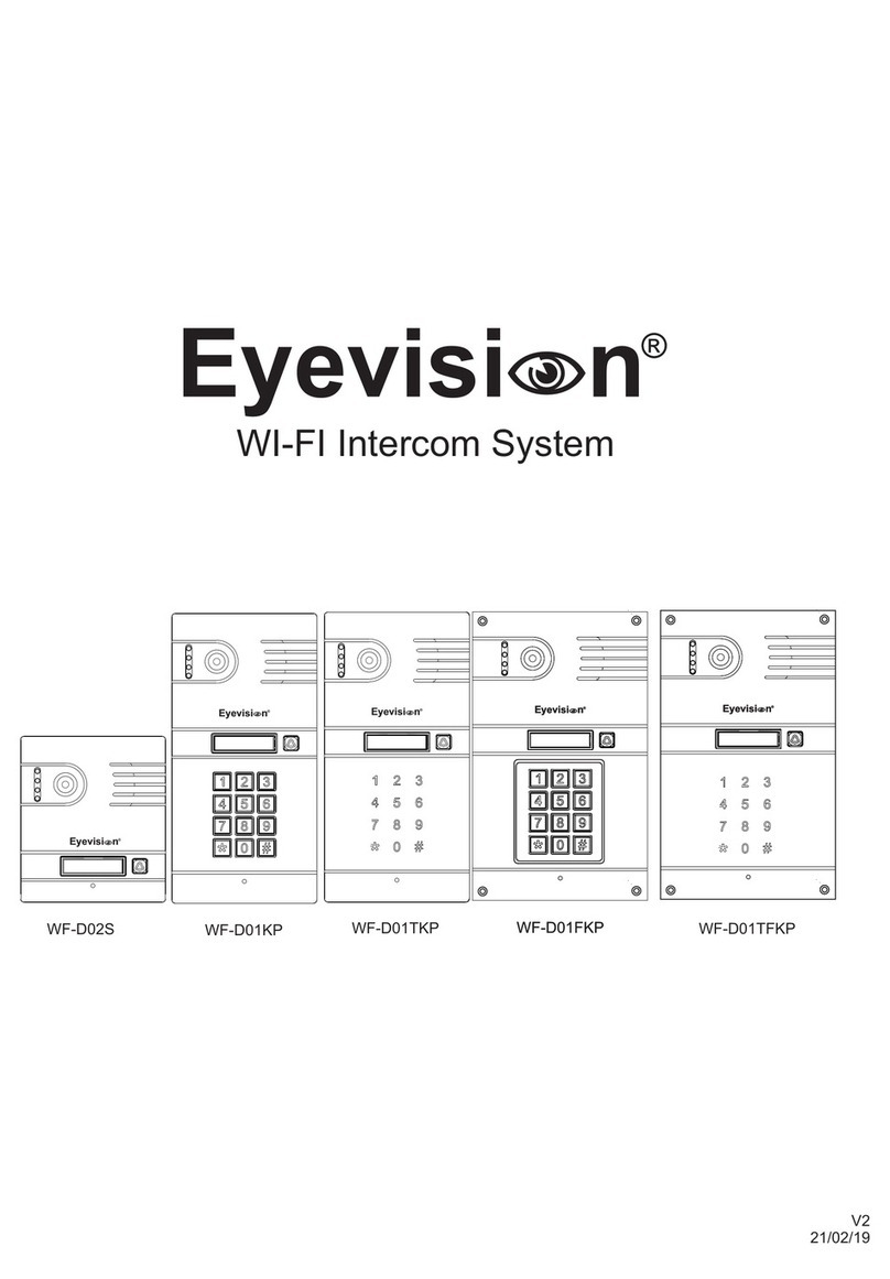
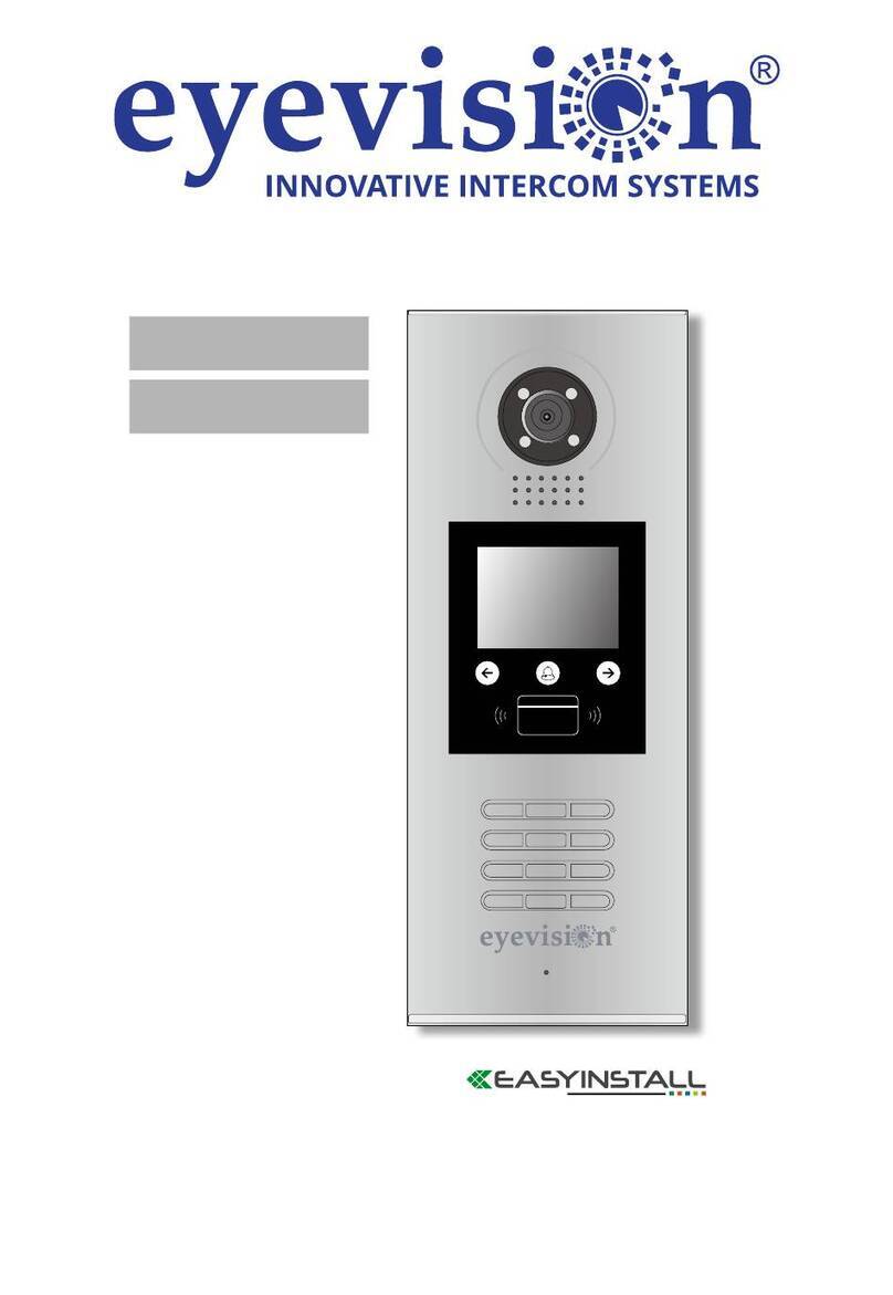
  9. Eyevision Intelli Series User manual

Eyevision Intelli Series User manual

Third Generation 4 Wire Intercom
Intelli Series Smart Intercom
DS 21 KP 21 WF 7 S 7
REV 0.2 040221
ŸDue to our constant developments, your purchased model functions may vary slightly to the instruction manual provided.
ŸWe always endeavor to try to update our manuals regularly in accordance with the level of new development.
ŸConnect this unit ONLY to other compatible units specified within this manual,
ŸConnecting anything else to this unit may damage it or prevent it from operating correctly.
ŸDo not place the power cords from the AC/DC adapters, camera or monitor where they can be pinched or cut.
ŸKeep cords away from children’s, pets and routine household traffic.
ŸDo not place heavy objects on power cords or cover cords with rugs or carpet.
ŸWhen the system is not in use, please unplug the AC/DC adapters from the wall outlet.
ŸSlots or openings in the back of the monitor are provided for ventilation and to ensure reliable operation of the video monitor or
equipment and to protect it from overheating.
ŸThese openings must not be blocked or covered.
ŸThe monitor should never be placed near a heater and should not be placed in a built in installation such as a bookcase unless proper
ventilation is provided.
ŸAll parts of the system should be protected from shocks and vibrations.
ŸFor cleaning the Lens & Screen please do the cleaning with a soft cotton cloth, do not use organic or chemical impregnate cloths. If
necessary please use a damp soft cloth to clean dust.
ŸImage distortion may occur if the video door phone is mounted too close to magnetic field e. g. Microwaves, TV, computer etc.
ŸPlease keep the indoor monitor away from wet areas, high temperature, dust, caustic and oxidation gas in order to avoid any
unpredictable damage.
Precautions
Quick Reference Diagram for Simple Installations
Table of Contents
This Page
Precautions
Quick Reference Diagram for simple installations
Page 1
Indoor Monitor overview, installation and specifications
Outdoor Unit overview, installation and specifications
Page 2
Cabling types and maximum lengths
Power Adapter
Page 3
Cabling Topology
Page 4
Wiring Overview
Page 5
KP 21 wiring, LED indicator, exit button electric striker and gate automation
connection
Page 6
DS 21 wiring, LED indicator, electric striker and gate automation
connection
Page 7
Common lock output (direct from monitors)
CCTV Integration
Alarm Sensor Integration
DVR Integration
Page 8
Keypad Programming
Page 9
Keypad Programming cont.
Page 10
Keypad Programming cont.
Indoor Monitor Touch Button Overview
Page 11
Using the indoor monitor (general use)
Page 12
Indoor Monitor Typical Configurations
Page 13
Indoor Monitor Typical Configurations cont.
Page 14
Surveillance and Alarm Settings
Page 15
Multimedia
Page 16
Multimedia cont.
Page 17
Tuya APP and Configuration
Page 18
Tuya APP and Configuration cont.
Page 19
Tuya APP and Configuration cont.
Automatic Gate OR Electric Striker
See Pages 5 & 6
Power Adapter for
KP 21 Model Only
RED=VCC
CHIME
Resolution 7" (1024*600)
Power Consumption Maximum 500mA
Power supply External power supply DC 12-15V
Operating Temp 0~+50℃
SD Card Requirment 2GB~32GB Class 10 micro SD Read/Write 10MB/S Min.
System Capacity 6 indoor monitors + 2 outdoor stations + 2 cameras (1MP MAX.)
Video Input Signal CVBS, CVI, TVI, AHD2.0
2 TFT display
4 Microphone
8 Mute Indicator
9 Mute switch
3 Touch Buttons
5 Speaker
7 SD card slot
1 Power Indicator LED
6 Menu/Settings Button
Indoor Monitor Specifications
Indoor Monitor Installation
Outdoor Unit Installation
Wall Plugs Wall Bracket
Cables
• Avoid installation near magnetic fields such as AC motors or
Lifts
• Avoid facing the camera to direct sunlight
• Install the camera lense equal with average height eye level
• Always ensure power is off when connecting and
disconnecting
• Ensure that the AC power supply is at least 30cm from the unit
to avoid interference.
15
7
9
86
2
3
4
Indoor Monitor Overview
o
120
Outdoor Unit Specifications Outdoor Unit Overview
Camera Sensor 1/3" CMOS Camera
Viewing Angle 120°
Definition 1.3MP
Night Viewing IR LED
Operating Temperature -0°C to +50°C
Operating Voltage 12-15V DC
Operating Current 30mA Standby 70mA Operational
Card Type IC Card (KP 21 Only)
IP Rating IP65
1 Speaker
2 Camera
3 Microphone
4 IR LED’s
5 IC Tag Sensor (KP 21 ONLY)
6 Keypad (KP 21 ONLY)
7 Call Button
8 Volume Adjustment Pot
9 Wiring
Outdoor Unit Installation with angle bracket Outdoor Unit Installation without angle bracket
• Avoid installation near magnetic fields such as AC motors or Lifts
• Avoid facing the camera to direct sunlight
• Install the camera lense equal with average height eye level where possible
• Always ensure power is off when connecting and disconnecting
• Ensure that the AC power supply is at least 30cm from the unit to avoid interference.
Page 1
KP 21 DS 21
wall plugs wall plugs
long countersunk
screws
long countersunk
screws
short black
countersunk screw
short silver
countersunk screw short silver
countersunk screw
Cabling
Power Adapter Limitations
4C ordinary unshielded wire and shielded wiring
3C ordinary unshielded + video cable(RG-59) connection method
CAT5/CAT6 network cable connection (not recommended)
≤50 meters
≤100 meters
≤80m (4*0.5mm²)
Page 2
Indoor Monitor & Outdoor Unit 15V 1A Power Adapter
* Max extendable distance is 3m
* Recommended cable to extend length is 14/020 pair
* Only one unit per power supply
≤50m (4*0.2mm²)
DC
AC
+
-
OUT
OUT
15V DC 1.5A Power Supply
* Max distance is 5m
* Recommended cable to is 14/020 pair or greater
* Max one unit per power supply
ALARM
SENSOR
ALARM
SENSOR
Through the settings menu each monitor MUST be set with
an ID number. The DEVICE ID Setting can be found in the
monitors MODE menu.
First Monitor (Master) is addressed 01
Second Monitor (Slave 1) is addressed 02
Third Monitor (Slave 2) is addressed 03
Fourth Monitor (Slave 3) is addressed 04
Fifth Monitor (Slave 4) is addressed 05
Sixth Monitor (Slave 5) is addressed 06
Cabling Topology
2C
4C
4C
RG 59 + 2C
RG 59 + 2C
2C
Automatic Gate
OR
Electric Striker
(See pages 5 & 6)
Automatic Gate
OR
Electric Striker
(See pages 5 & 6)
2C
2C
2C
2C
2C
2C
COMMON
Automatic Gate
OR
Electric Striker
(See page 7)
Page 3
Power Adapter for
KP 21 Model Only
Power Adapter for
KP 21 Model Only
See Page 7
See Page 7
See Page 7
NOTE: The monitor with the
alarm sensor connected is the
only monitor that alarm in the
system that will alarm and
record, this should typically be
Device 01. CCTV cameras must
be connected to the same
monitor.
CCTV
CVBS , TVI, CVI, AHD
1.3MP Max.
WHITE=ALARM
WHITE=ALARM
ALARM
SENSOR 2
ALARM
SENSOR 1
Wiring Overview
COMMON
Automatic Gate
OR
Electric Striker
See Page 7
DOOR 1
Automatic Gate
OR
Electric Striker
See Pages 5 & 6
DOOR 2
Automatic Gate
OR
Electric Striker
See Pages 5 & 6
Red & Black
Red & Black
Page 4
Power Adapter for
KP 21 Model Only
Power Adapter for
KP 21 Model Only
See Page 7
See Page 7
RED=VCC
RED=VCC
CHIME CHIME
External Chime System
N/O Relay (voltage free)
Latches for 5 seconds upon doorbell ring
NOTE: The monitor with the alarm
sensor connected is the only monitor
that alarm in the system that will alarm
and record, this should typically be
Device 01. CCTV cameras must be
connected to the same monitor.
CCTV
CVBS , TVI, CVI, AHD
1.3MP Max.
Red (Intercom Switching Power Line to Indoor Monitor)
Black (Intercom Ground Line to Indoor Monitor)
White (Intercom Audio Line to Indoor Monitor)
Yellow (Intercom Video Line to Indoor Monitor)
}
Green (Normally Open Circuit)
Brown (Normally Closed Circuit)
Orange (Relay Common)
}
Blue (Exit Button Normally Open Connection)
}
Grey (Power Adapter Negative)
Purple (Power Adapter Positive)
}
Intercom Line
to indoor monitor
Unlock Relay
Exit Button
Power Adapter
Green (Normally Open Circuit)
Orange (Relay Common)
Push Button/ OSC Input
Common/Ground for Push Button/ OSC Input
Grey (System Negative/Power Adapter Negative)
Blue (Exit Button)
Fail Secure Electric Striker Connection (Power ON to Unlock)
KP 21 Outdoor Station
Fail Safe Electric Striker Connection (Power OFF to Unlock)
Automatic Gate Connection
Exit Button Connection
Door Station LED
Wiring Overview
White LED
Standby (Without Motion Detection)
Green LED
Unlocking Outdoor Station Electric Striker or
Automatic Gate
RED LED
Standby (With Motion Detection)
In a Video Monitoring/Communication State
Green (Normally Open Circuit)
Grey (Power Adapter Negative)
Orange (Relay Common)
Purple (Power Adapter Positive)
JOIN
Black
Black/White
Power
Adapter
-
-
+
+
Orange (Relay Common)
Grey (Power Adapter Negative)
Brown (Normally Closed Circuit)
Purple (Power Adapter Positive)
JOIN
Black
Black/White
Power
Adapter
-
-
+
+
Purple (Power Adapter Positive)
Black
NO
COM
Black/White
Power
Adapter
-+
12V DC
250mA Max.
12V DC
250mA Max.
Page 5
Red (Intercom Switching Power Line to Indoor Monitor)
Black (Intercom Ground Line to Indoor Monitor)
White (Intercom Audio Line to Indoor Monitor)
Yellow (Intercom Video Line to Indoor Monitor)
}
Green (Normally Open Circuit)
Brown (Normally Closed Circuit)
Orange (Relay Common)
}
Blue (VCAM+)
}
Grey (GND)
Intercom Line
to indoor monitor
Unlock Relay
DVR Mode
Green (Normally Open Circuit)
Orange (Relay Common)
Push Button/ OSC Input
Common/Ground for Push Button/ OSC Input
Fail Secure Electric Striker Connection (Power ON to Unlock)
Fail Safe Electric Striker Connection (Power OFF to Unlock)
Automatic Gate Connection
Door Station LED
Wiring Overview
White LED
Standby (Without Motion Detection)
Green LED
Unlocking Outdoor Station Electric Striker or
Automatic Gate
RED LED
Standby (With Motion Detection)
In a Video Monitoring/Communication State
Green (Normally Open Circuit)
Orange (Relay Common)
JOIN
JOIN
-
+
Orange (Relay Common)
Brown (Normally Closed Circuit)
Black
Black/White
Power
Adapter
-
-
+
+
12V DC
250mA Max.
12V DC
250mA Max.
Page 6
Indoor Monitor Line
DS 21 Outdoor Station
CCTV Wiring
Alarm Sensor Wiring
DVR Mode for KP 21
To Indoor Monitor
To a vacant
camera port
Swipe the add tag
Swipe the add tag to complete programming
Swipe the add tag a second time
Swipe the add tag a third time
Swipe the Delete tag to turn on the DVR output
Swipe the Delete tag again to turn off the DVR output
SWIPE ADD TAG
SWIPE ADD TAG
SWIPE ADD TAG
SWIPE ADD TAG
Note:
1. You would need two additional tags to be allocated as add and delete tags to allow for this programming method.
2. Add and Delete tags must be programmed first before beginning this process.
SWIPE DELETE TAG
SWIPE DELETE TAG
Sensor Common
& NEGATIVE
BLACK=VIDEO GND
CCTV camera draws greater than
200mA or is not 12V DC
compatible or Distance is too
great and needs localised 12V DC.
• Required if motion detection setting will be enable for the CCTV camera or its ALARM
feature.
• Supports Normally Open/Normally Closed Sensors, configurable from the ALARM menu.
• If the sensor requires power from the intercom the maximum draw is 50mA in working
state on 12V DC.
•NOTE: The monitor with the alarm sensor connected is the only monitor that alarm in
the system that will alarm and record, this should typically be Device 01. CCTV cameras
must be connected to the same monitor.
Acceptable cameras to connect into
the system are CVBS, CVI, TVI and AHD with a
max. of 1.3MP.
If the camera does not show on the CAM1/CAM2
input the system may need a reboot to re-detect the
camera technology in use. This can be found by
Main Menu > System > System Info.
If it still does not show there is a wiring error or a
camera fault.
BLACK=
RED=12V POSITIVE
WHITE= Sensor NO/NC
VIDEO GND
& NEGATIVE
CCTV camera draws less than
250mA at 12V DC.
BLACK=
RED=12V POSITIVE
Option 1 Option 2
Common Door Lock Output (From monitor only)
For Automatic Gates For Electric Strikers
To Automatic Gate
Next Monitor
POWER SUPPLY CONTROL
MODEL: K80
CONTROL -
CONTROL+
PUSH
GND
+12V
- COM
+ NC
+ NO
+
TIME
Next Monitor
Page 7
RED=VCC
To Indoor Monitor
To a vacant camera port
RED=VCC
GREY = GND
GREY = GND
PURPLE = +12V
BLUE = +V CAM +
DVR Mode for DS 21
Note: When using DVR mode you must now use a power adapter to power the outdoor station constantly
#
#
#
Type * then swipe an already working tag
Type the current PIN (The default which cannot unlock is 0000)
Type the new PIN and press # (4 Digits)
Repeat the new password and press #
#
#
#
#
9
9
1
1
9
9
9
9
1
1
Default PIN is 999999, if the PIN has been changed in the past then use the current PIN
Type 0 to enter the PIN programming menu
Type 1 to enter the Tag programming menu
Type 11# to enter the common PIN menu
Type in a user position between 001 and 200
Type the new PIN and press # (4 or 6 Digits)
Swipe the tag
Repeat the new PIN and press #
Press *, * then # to exit
Successful Command
Failed Command
Returned one step in Menu
Press *, * then # to exit
*#
#
#
9
6
6
9
6
6
9
6
6
9
6
6
9
6
6
9
6
6
#
0
77
Changing the Admin PIN
Default PIN is 999999, if the PIN has been changed in the past then use the current PIN
Type 0 to enter the PIN programming menu
Type 77# to enter the admin PIN menu
Type the new PIN and press # (6 Digits)
Repeat the new PIN and press #
*#
9999
99
Entering and Exiting Admin
Buzzer Alerts
Default PIN is 999999, if the PIN has been changed in the past then use the current PIN
*
4
4
4
4
4
4
0
4
4
00
0
Providing a User with a Tag (or changing) there PIN number
*
*
#
#
#
#
#
9
9
1
SWIPE
SWIPE
1
*
*
*
*
*
*
*
*
9
9
1
1
9
9
1
1
1
1
#
1 #
0
1
1
0
1
0
Changing the Common Unlock PIN
Adding a User Tag
Bi!
Bi!
Bi!
Bi!
Bi!
Bi!
Bi!
Bi! Bi!
Swipe the add tag
Swipe the add tag to complete programming
Swipe the add tag a second time
Swipe the add tag a third time
Swipe the new users tag, you can swipe through multiple one after the other
SWIPE ADD TAG
SWIPE ADD TAG
SWIPE ADD TAG
SWIPE ADD TAG
SWIPE NEW USER TAG
Adding User Tags using the Admin Add Tag
Note: Adding tags using this method does not give each tag a USER ID number, this means the tags can only be deleted by a complete clear of all user
tags OR the tag being available and present for deleting.
#
9
99Default PIN is 999999, if the PIN has been changed in the past then use the current PIN
Type 6#
Swipe the tag to be nominated as the add tag
Swipe the tag to be nominated as the delete tag
Press *, * then # to exit
*#
#
9
SWIPE ADD TAG
SWIPE DELETE TAG
**
99
6
Adding Administrator ADD/DELETE tags
Page 8
*#
9999
99
#
#
3
5
x
x
x
x
Changing the Security Settings
Default PIN is 999999, if the PIN has been changed in the past then use the current PIN
Type 3 to enter the Access Control Setup Method
Type 5 to enter the Security Settings
Type the setting number and press #
#
#
*
*
*
*
Press *, * then # to exit
#
#
#
0
0
0
0
1
2
Only unlocking by Tag
Unlocking by PIN or Tag (Default)
Unlocking by Tag first followed by PIN
#
#
#
0
0
0
0
1
2
No Security (Default)
Swiping non-registered card or 10 incorrect PINS within a 5 minute period results in 2 minute shut down of the unlocking system from
the outdoor station along with a doorbell call to the monitor.
Swiping non-registered card or 10 incorrect PINS within a 5 minute period results in an alarm output from the buzzer for 1 minute
along with a doorbell call to the monitor.
*#
9999
99
Changing the Access Control Method
Default PIN is 999999, if the PIN has been changed in the past then use the current PIN
*#
9999
99
#
4
05
Default PIN is 999999, if the PIN has been changed in the past then use the current PIN
Type 4 to enter the unlock time setting menu
Type the amount of seconds (00-99) then press #
#
**Press *, * then # to exit
Setting the Unlock Time for PIN number and Tag Users
Note for the monitor its unlocking time can be set via the monitor itself
#
9
99Default PIN is 999999, if the PIN has been changed in the past then use the current PIN
Type 2 to enter into deleting state
Type in the used user ID to be deleted between 001 and 200
Press *, * then # to exit
*
#
9
**
99
1 #
2
00
Deleting a User by there ID number
*#
#
#
9
SWIPE
**
999
99
2
Default PIN is 999999, if the PIN has been changed in the past then use the current PIN
Type 2 to enter into deleting state
Swipe the tag
Press *, * then # to exit
Deleting a User by using there tag
Swipe the delete tag
Swipe the delete tag to complete programming
Swipe the delete tag a second time
Swipe the delete tag a third time
Swipe the users tag you wish to delete, you can swipe through multiple one after the other
SWIPE DELETE TAG
SWIPE DELETE TAG
SWIPE DELETE TAG
SWIPE DELETE TAG
SWIPE USER TAG
Deleting User Tags using the Admin Delete Tag
Note This will not reset the common PIN.
#
9
99Default PIN is 999999, if the PIN has been changed in the past then use the current PIN
Type 2 to enter into deleting state
Type in a 88#
Swipe any programmed tag
Press *, * then # to exit
*
#
#
9
**
99
8 #
2
8
Deleting ALL User Tags
SWIPE USER TAG
Page 9
Reset Process (without admin PIN)
This process will reset back to default parameters as listed below
• Admin PIN to 999999
• Public unlock PIN to 123456
• Unlock time to 2 seconds
• Security mode to No Security
1. Outdoor station power should be OFF
2. Temporarily connect the Exit Button Wire to the power supply Negative for the systemBLUE GREY
alternatively if an Exit Button is installed an assistant could hold the button down until the below steps are complete
3. Turn the outdoor station power adapter to ON
4. A Bi Bi Bi sound will be heard from the keypad to indicate reset complete
5. Disconnect blue wire or have the assistant release the exit button exit button.
*#
9999
99
#
0
99
Reset Process (with admin PIN)
Default PIN is 999999, if the PIN has been changed in the past then use the current PIN
Type 0 to enter the menu
Type 99# to perform the reset
#
**Press *, * then # to exit
Down
Up
Unlock the door striker/gate related to the outdoor station
Transfer/
intercom
Call transfer/Internal intercom/Color Contrast
1. Standby mode long press the button start internal intercom
2. During monitor and door station on conversation long press the button transfer call to slave monitor.
3. During conversation or monitoring, short press the button start Colour Contrast.
Monitor Door 1/Cam 1/Door 2/Cam 2
1. Start conversation with door station
2. Monitor monitoring door station, press the button start conversation with door station
3. During conversation, press the button hang up
4. During make menu setting, press the button exit
Unlock the COMMON door striker/gate by press this button
Confirm/Enter into main menu
1. Standby mode press the button to enter main menu
2. Setting parameter press button confirm
3. During talking/monitoring mode, press button start recording/snapshot/stop recording
4. Playing music/video/picture mode, press the button pause/play
5. Playing music/video, long press the button adjust volume
Setting
Monitoring
Unlock
Answer/
Hang up
“+”
“-”
Gate
Unlock
Indicates the intercom is muted from the switch on the side of monitor
Mute
Touch Button Overview
This process will reset back to default parameters as listed below
• Admin PIN to 999999
• Public unlock PIN to 123456
• Unlock time to 2 seconds
• Security mode to No Security
Page 10
Photo Frame:
Motion Detection is disabled when Photo Frame is switched ON
on
6
Play time interval:
2
2
3
3
4
4
5
5
6
6
When a visitor presses the doorbell the indoor monitor(s) will ring for a total of 30 seconds before returning to standby. At anytime during the
ringing time a user can answer from any of the monitors by pressing the button. At this point there is hands free communication in both
directions.
If required he user can press to operate the gate connected to the outdoor station that is in communication or can press to operate
the gate that is connected to the common release.
In a Multi indoor monitor installation if the user answers on one of the indoor monitors but decides the call is for another user within the
home or another room the call can be transferred by pressing during the call then choosing the extension from the displayed list
. they wish to transfer to by cycling using the keys and to select._______________________
Once a call is transferred the indoor monitor will return to standby and the target monitor will ring with the guest showing.
Visitor Calls
Call Transfers
Intercom Call
Monitoring
Whilst in standby press and hold the button until the intercom extensions list is displayed. Cycle using the
keys and to select the target monitor. Once the target indoor monitor presses to answer there will be hands free audio communication
between both points. Either party can end communication by pressing the button
From Standby press the button to display DOOR 1, you can cycle to Cam 1 > Door 2 > Cam 2 by pressing consecutively.
If a Micro SD card is installed you can take a Video/Photo (depending on the setting in the “Mode” menu) by pressing .
Note that by default Door 2, CAM 1 and CAM 2 are all enabled. Door 2 can be disabled from the “MODE” Menu and CAM 1/CAM2 can be disabled
from the “Alarm” menu.
10:50
Monday
07-08-2020
System
2019-04-032019-04-03
23:59:5823:59:58
Sunday
Alarm
Photo Frame
Record
Mode
Media
There are three different modes of standby that can be used, option 1 and 2 are activated by pressing
Option 1: which is when the indoor monitor is in an idle state if you press it will display only a message indicator
if there are any messages. See clock switch settings and DISABLE. It will timeout after TWO minutes.
Option 2: which is when the indoor monitor is in an idle state if you press it will display the time and date. See
clock switch settings and ENABLE It will timeout after TWO minutes.
Option 3: Digital photo frame which is when the indoor monitor is in an idle state it will loop through stored photos
on the SD card. See Digital photo frame
Note: When using digital photo frame mode motion detection will automatically be disabled.
From the menu choose navigate to “Photo Frame”. From here you can ENABLE and DISABLE the feature along with set
the interval of each photo anywhere from two seconds and up to 10 seconds.
Notes:
1.When using digital photo frame mode you will not have an indicator to let you know there is an unseen message.
2. For digital photo frame the photos must be 1920x1080 resolution.
3. Each photo cannot exceed 3MB.
4. For photo storage all photos must be places on the micro SD card in the folder structure USER\photo noting that the
directory is case sensitive.
Standby
Enable/Disable Digital Photo Frame
In standby mode, press to monitor then press to bring up adjustment mode.
Within you can adjust colour, brightness, contrast and saturation.
Select the option and press button. Arrow Keys to increase or decrease its value.
Then press button again to save the changes.
door1
05 25 25 25
Values adjustable from 0 to 50. (Default: 25).
Values adjustable from 0 to 5(Default: 5).
Values adjustable from 0 to 50. (Default: 25).
[Bright]:
[Talking Volume]:
[Contrast]:
Values adjustable from 0 to 50. (Default: 25).
[Saturation]:
Realtime Monitoring Adjustments
[Return]: Press to return.
Page 11
Navigate to “Mode” then from the Device ID setting you can cycle from 01 to 06. This number directly
corelates to the call transfer and intercom function when selecting a target indoor monitor.
Notes
1. The first monitor in the intercom in the line should always be set to 01
2. No two monitors should share the same ID number to avoid conflicts
Navigate to “Mode” then scroll to Door 2 Status. To Enable a second outdoor station this setting
should be turned ON for the FIRST monitor in the intercom line ONLY (Device ID 01).
Navigate to “Mode” then scroll to Door 1 or Door 2 Unlock time depending on which (or both) need to be
set and adjust to the required time between 2 seconds and 10 seconds.
This is the respective unlocking time of each indoor monitor and should only be set on the FIRST monitor in
the intercom line (Device ID 01).
Note: KP 21 Keypad models also need the unlock time set on the outdoor station itself (see keypad
programming).
Navigate to “Mode” then scroll to room unlock time. This is the time setting for the unlocking time of
the common gate which is connected directly to the monitor.
Note that this is NOT the outdoor station unlock time.
Navigate to “Mode” then scroll to record mode. This is to set the type of recording for the systems
automatic *when a guest rings the door bell) and manual captures wether it be a video recording or
a photo snapshot.
Note that a micro SD card must be installed to use this feature.
Navigate to “Mode” then scroll to motion detection. Motion detection can be enabled for one specific
camera of the two outdoor station inputs. When enabled it will automatically call up the video for the
chosen motion detection camera and take a capture based on the record mode setting.
Note that for the outdoor station it is considered sensitive and good for enclosed front door areas which
would not see any movement normally. It should not be enabled when it could see any movement
normally from trees, pedestrians etc.
Navigate to “Mode” then scroll to motion message. If enabling the message feature after no answer from
any user on any indoor monitor and once the ringing duration times out (see volume menu) then the
guest will be prompted with a message “no one is at home could you please leave a message”
Note that a micro SD card must be installed to use this feature.
Setting Indoor Monitor Number (Device ID)
Enabling/Disabling a Second Outdoor Station
Door 1 and Door 2 Unlock Time
Room Unlock Time
Record Mode
Motion Detection
Message
Eingestellte Apparat-ID 01
Bewegungserkennung Kamera 1
Aufnahmemodus
Schnappschuss
Tür2 Entsperrzeit 05
Tür1 Entsperrzeit 10
Tür 2Status an
Nachricht an
Door2 status
Device ID
01
Motion detection Door 2
Record mode Video
Room unlock time
02
02
Door2 unlock time
02
Door1 unlock time
On
Message On
Eingestellte Apparat-ID 01
Bewegungserkennung Kamera 1
Aufnahmemodus
Schnappschuss
Tür2 Entsperrzeit 05
Tür1 Entsperrzeit 10
Tür 2Status an
Nachricht an
Door2 status
Device ID
01
Motion detection Door 2
Record mode Video
Room unlock time
02
02
Door2 unlock time
02
Door1 unlock time
On
Message On
Eingestellte Apparat-ID 01
Bewegungserkennung Kamera 1
Aufnahmemodus
Schnappschuss
Tür2 Entsperrzeit 05
Tür1 Entsperrzeit 10
Tür 2Status an
Nachricht an
Door2 status
Device ID
01
Motion detection Door 2
Record mode Video
Room unlock time
02
02
Door2 unlock time
02
Door1 unlock time
On
Message On
Eingestellte Apparat-ID 01
Bewegungserkennung Kamera 1
Aufnahmemodus
Schnappschuss
Tür2 Entsperrzeit 05
Tür1 Entsperrzeit 10
Tür 2Status an
Nachricht an
Door2 status
Device ID
01
Motion detection Door 2
Record mode Video
Room unlock time
02
02
Door2 unlock time
02
Door1 unlock time
On
Message On
Eingestellte Apparat-ID 01
Bewegungserkennung Kamera 1
Aufnahmemodus
Schnappschuss
Tür2 Entsperrzeit 05
Tür1 Entsperrzeit 10
Tür 2Status an
Nachricht an
Door2 status
Device ID
01
Motion detection Door 2
Record mode Video
Room unlock time
02
02
Door2 unlock time
02
Door1 unlock time
On
Message On
Eingestellte Apparat-ID 01
Bewegungserkennung Kamera 1
Aufnahmemodus
Schnappschuss
Tür2 Entsperrzeit 05
Tür1 Entsperrzeit 10
Tür 2Status an
Nachricht an
Door2 status
Device ID
01
Motion detection Door 2
Record mode Video
Room unlock time
02
02
Door2 unlock time
02
Door1 unlock time
On
Message On
Eingestellte Apparat-ID 01
Bewegungserkennung Kamera 1
Aufnahmemodus
Schnappschuss
Tür2 Entsperrzeit 05
Tür1 Entsperrzeit 10
Tür 2Status an
Nachricht an
Door2 status
Device ID
01
Motion detection Door 2
Record mode Video
Room unlock time
02
02
Door2 unlock time
02
Door1 unlock time
On
Message On
Page 12
Language English
Navigate to “System” then volume. From this menu you can set the scheduled time for different ring
volume levels (1-10) for Morning (Volume 1)/Afternoon(Volume 2)/Evening(Volume 3) and the
duration of the ringing time.
Button Voice sets the audible feedback ON/OFF per touch button press on the indoor monitor..
Ringback Enables the ringtone to be audible at the outdoor station.
Navigate to “System” then ring tone. From this menu you can through the mode setting choose
wether to use from one of the default ten ring tones or choose a custom ring tone.
Note: When choosing the mode it will be common to both outdoor stations. Meaning if default both
will need to use a default ring tone if custom both will need to be a custom ring tone.
If using a custom ring tone the mp3 file(s) must be stored on the micro SD card in the folder
structure USER\ring noting that the directory is case sensitive.
Each custom ring tone must be named ring_x.mp3 replacing the x with a numerical number in
consecutive sequence. Example: The first is ring_1.mp3 and the second is ring_2.mp3.
Navigate to “System” then system info.
This screen will display Firmware and MCU version Mac address and ID number.
It will also display the micro SD card capacity, used space and allow formatting of the micro SD.
Furthermore GET ID can be used for an address ID Update/Change.
Reboot can be used to restart the monitor without disconnecting the power supply.
Clock Switch on
Format YY-MM-DD
Date 2019
01
04
38
07
43
Time
Ring vol1:
Start Time End Time Volume Duration
Ring vol2:
Ring vol3:
Button Voice:
Ringback
06
12
18
on
on
12
18
06
00
00
00
00
00
00
07
07
07
30
30
30
Navigate to “System” then Language. You can choose from English, Hebrew, French, Spanish,
Portugese, Russian, Turkish, Chinese, Polish, Arabic and German.
Navigate to “System” then Time.
Here you can set the date and time (in 24 Hr format). This is critical for any system recording as well
as the clock display.
You can also ENABLE-DISABLE the Clock Switch Setting for the standby screen. Enabling Clock Switch
will set the system standby to Clock Mode, Disabling will set the system Standby into Simple Mode.
Language
Time and Date
Intercom Ring Volume & Enabling Ringtone outside
Ringtone
Information
Door 2 ring
Mode Default
Door 1 ring Default 1
Default 2
SD capacity
FW ver. AH-V1.0.1036
Reboot
0MB/0MB
Format
MCU ver. MCU-0_6_45
confirm
confirm
ID:
MAC: 18:c8:e7:2d:6a:25
brdz32e9d0e2dc762ea2
Get ID: confirm
Page 13
CAM2 Ring Time 05
CAM2 on
Sensor Type 2 NO
CAM1 Ring Time 05
CAM1 on
Sensor Type 1 NO
Alarm Record Video
CAM2 Ring Time 05
CAM2 on
Sensor Type 2 NO
CAM1 Ring Time 05
CAM1 on
Sensor Type 1 NO
Alarm Record Video
CAM2 Ring Time 05
CAM2 on
Sensor Type 2 NO
CAM1 Ring Time 05
CAM1 on
Sensor Type 1 NO
Alarm Record Video
CAM2 Ring Time 05
CAM2 on
Sensor Type 2 NO
CAM1 Ring Time 05
CAM1 on
Sensor Type 1 NO
Alarm Record Video
Navigate to “Alarm” then from Alarm Record you can set the type of recording for the systems
sensor based captures for the surveillance cameras wether it be a video recording or a photo
snapshot.
Note:
1. A micro SD card must be installed to use this feature.
2. The recording time is 2 minutes.
NOTE: The monitor with the alarm sensor connected is the only monitor that alarm in the system
that will alarm and record, this should typically be Device 01. CCTV cameras must be connected to
the same monitor.
Navigate to “Alarm” then CAM1/CAM2 you can set each individual camera to be ON/OFF.
This should only be set on the first monitor in the line (DEVICE 01).
Navigate to “Alarm” then Sensor Type 1/Sensor Type 2 you can set the type of sensor that is being
used for the detection of each camera. You can choose NO (normally Open), NC (Normally Closed) or
OFF to Disable.
NOTE: The monitor with the alarm sensor connected is the only monitor that alarm in the system
that will alarm and record, this should typically be Device 01. CCTV cameras must be connected to
the same monitor.
Navigate to “Alarm” then ring time, from there you can set the ringing time for the alert of each
camera on the indoor monitor, this can be set from 5 seconds up to 20 seconds.
NOTE: The monitor with the alarm sensor connected is the only monitor that alarm in the system
that will alarm and record, this should typically be Device 01. CCTV cameras must be connected to
the same monitor.
Alarm Record
Enabling/Disabling Surveillance Cameras
Sensor Type
Alarm Ring Time
Page 14
Music Photo
ReturnFile
manager system
USER
DCIM
ring
DIALOG
are you sure to delete?
Yes No
Navigate to “Media”. You can choose from within this menu the type of file you wish to view wether it
be Music for audio files, photo for images or file for general navigation along with firmware upgrade
files.
Note: ALWAYS disconnect the power to the indoor monitor whenever inserting or removing the
micro SD card.
Navigate to “Media” then “Music”.
Using the button music can be adjusted through the five different playing modes.
[Play In Sequence]: Play all songs from top to bottom of list. Stop playing after the last song is played.
[Single Play]: Stop automatically after playing the current song.
[Single Cycle]: Play the same song repeatedly without stopping.
[List Cycle]: Repeat all songs in sequence. Restart playback from the first song after finishing the last.
[Random Play]: Play all songs in random order without stopping.
For volume adjustment hold down the until the volume appears on the screen, then use and
to lower and raise the volume.
For mp3 music file placement on the micro SD card the folder structure should be USER/Music.
Navigate to “Media” then “Photo”.
Using the and you can scroll up and down through the list to the file name then press the
to view the photo. Note that it will automatically move to the next photo after two seconds.
For .jpg photo file placement on the micro SD card the folder structure should be USER/Photo.
Note: ALWAYS disconnect the power to the indoor monitor whenever inserting or removing the micro
SD card.
Maximum photo is 1920x1080 resolution and 3MB or less.
Navigate to “Media” then “File Management”.
[Delete file]: Press the Arrow keys to highlight a file to delete. Then press setting icon and hold until a
pop-up window appears with the message “Delete File?” Use the Arrow keys to select “Yes” and press
setting icon to delete file. Otherwise, press setting icon when “No” is selected to cancel.
[DCIM]: This DCIM folder is automatically created by the Monitor for saving files created for the Record
Centre. It contains the “Photo” & “Video” folders. The “Photo” folder saves the automatic snapshots and
manually captured photos. Similarly, the “Video” folder saves the automatic and manually recorded
videos by the monitor.
[USER]: The USER directory contains the “Music, Photo, Ring, Update” folders. Note: These directory &
names are case sensitive.
- “Music” folder stores the MP3 music files.
- “Photo” folder stores JPG pictures for the digital photo frame.
- “Ring” folder stores the custom ringtones.
- “Update” folder for upgrade files. USER folder stores “Music, Photo, Ring, Update” folders.
[Upgrade]: Put upgrade file (xxx.dd is the program file) in the Update folder, select upgrade file xxx.dd
and press setting icon to pop up the window “Upgrade?” Select“Yes” and press setting icon to confirm
upgrade and wait for the upgrade to succeed. “No” Press setting icon to close the window.
[MCU Upgrade]: Put MCU file (xxx.bin is the MCU file) in the update folder, select MCU file xxx.bin and
press setting icon to pop up a window “Upgrade?” Select “Yes” and press setting icon to confirm to
upgrade and wait for the upgrade to succeed. Select “No” Press setting icon to close the window.
Note: During system upgrading, do not remove SD card, power off, or disable indoor monitor. After
the upgrade is complete, the device will restart.
Media Menu
Music
Photos
File Managment
Page 15
Video Picture Return
Navigate to “Record Centre”. You can choose from within this menu the type of recording you wish
to view wether it be Video or Picture (Photo).
Navigate to “Record Centre” then “Video”. From within this menu you can scroll through the list of
recorded videos using the and you can scroll up and down through the list to the file name
then press the to view the recording.
To delete this can be done through the Media > File menu.
Navigate to “Record Centre” then “Picture”. From within this menu you can scroll through the list of
recorded photos using the and you can scroll up and down through the list to the file name
then press the to view the recording.
To delete this can be done through the Media > File menu.
Media Menu
Video Recordings
Video Recordings
Page 16
APP Configuration
APP Install and Registration (All Users)
APP Preparation (Home Owners Device)
Monitor Preparation for Wi-Fi Connection
1. Download Tuya Smart from the APP Store on your Android/Apple Device.
2. Open the App and register an account ensuring you select “Australia” as the country
3. Login after registration. NOTE: Each user must register there own account.
1. Select System
1. Go to “Me” 2. Go to
“Home Management”
3. Select “My Home...”
4. Name the home
5. Set the Location
6. Deselect ALL
the rooms
except the one
where the indoor
monitor is
installed.
System
2019-04-032019-04-03
23:59:5823:59:58
Sunday
Alarm
Photo Frame
Record
Mode
Media
TimeTime
VolumeVolume
LanguageLanguage
RingRing
InformationInformation
Network setting
2. Select Network Setting 3. Select WiFi Set 4. Select AP mode then Deselect
the monitor will restart and create
a hotspot
Video
WiFi Set Server Set
Select Mode AP MODE


①
②
②
③
③
④
④
⑤
⑤
⑥
⑥
⑦⑧
⑩
Snapshot
Unlock
Play back
Mute
Switch
Channel
Albums
Recording
Common
Hang up / Exit.
Unlock (Connected to outdoor station)
Switch camera image: During talking/monitoring, press the button view door1, door2, camera1, camera2.
Playback: Make sure monitor insert MicroSD card, and support playback calling/monitoring video record.
Common Unlock (Connected to the monitor)
Video record: During talking/monitoring, press the button start video recording.
Full screen: Press the button display full screen.
Setting:
Photo albums: Android system smart phone save snapshot picture on App; IOS system smart phone
save snapshot picture on mobile phone photo albums.
Audio Status
Mute
Snapshot: During talking/monitoring mode, press the icon snapshot image(Android system smart phone
save snapshot picture on App; IOS system smart phone save snapshot picture on mobile phone photo
albums.
①


⑦
⑧
⑩
APP Interface
Unlock
Steps continue on next page
Page 17
7. Press Save
Monitor to APP Connection (Home Owners Device)
1. Ensure you are on the
correct home then go to
“Add Device”
2. Select Video
Surviellance then
Smart Doorbell
3. From the top right
change from QR CODE
to AP MODE
Then Check the prompt
tone checkbox and press
next.
No tone or LED is
expected with this
system.
5. Select go to Connect
and choose the
SmartLife-xxxxx hotspot
created by the indoor
monitor
then press back
6. Once it reaches 100%
it has been added
successfully
7. Successfully Completed
Touch the pen
to edit the
name
ENSURE you are connected to your home Wi-Fi 2.4GHZ network
If at anytime you are prompted to accept permission including location please accept
4. Select the home WiFi
network (2.4GHZ) and
input the password
1. In a case where the phone tries to reconnect to SmarLife-xxx hotspot
then from your Wi-Fi settings choose to forget this network.
2. After successfully completing the Tuya Smart App will provide further
instructions to set the phone to always receive the notifications, these
must be followed for reliable notifications.
3. If you are receiving notification without audio try turning off your
bluetooth as it may be sent to another device such as car audio, smart
watch etc.
Page 18

This manual suits for next models

4

Other Eyevision Intercom System manuals

Eyevision EV-IP-KP22 User manual

Eyevision

Eyevision EV-IP-KP22 User manual

Eyevision EV-TRUWL7-KP22 User manual

Eyevision

Eyevision EV-TRUWL7-KP22 User manual

Eyevision EV-D301 User manual

Eyevision

Eyevision EV-D301 User manual

Eyevision WF-D02S User manual

Eyevision

Eyevision WF-D02S User manual

Eyevision EV-V4L User manual

Eyevision

Eyevision EV-V4L User manual

Eyevision EV-H298 User manual

Eyevision

Eyevision EV-H298 User manual

Eyevision EV-D298F Series User manual

Eyevision

Eyevision EV-D298F Series User manual

Eyevision EV-DMR18S User manual

Eyevision

Eyevision EV-DMR18S User manual

Popular Intercom System manuals by other brands

KOCOM KIP-300 manual

KOCOM

KOCOM KIP-300 manual

fortessa DIGI-2 Technical manual

fortessa

fortessa DIGI-2 Technical manual

FRELAN EXITEC Fitting instructions

FRELAN

FRELAN EXITEC Fitting instructions

Panasonic VL-MV72AZ user guide

Panasonic

Panasonic VL-MV72AZ user guide

nedis DOORP10CGT user manual

nedis

nedis DOORP10CGT user manual

Videx ESVK/KRV782 Series Installation handbook

Videx

Videx ESVK/KRV782 Series Installation handbook

Sancon SAMCOM FTAN20AA instruction manual

Sancon

Sancon SAMCOM FTAN20AA instruction manual

Telguard Bespoke install guide

Telguard

Telguard Bespoke install guide

EtiamPro EDS201B user manual

EtiamPro

EtiamPro EDS201B user manual

HME Clear-Com ProGrid PG8-INTERCOM-FX user guide

HME

HME Clear-Com ProGrid PG8-INTERCOM-FX user guide

Niko 10-570 user manual

Niko

Niko 10-570 user manual

Bell System bellissimo Installation & operation manual

Bell System

Bell System bellissimo Installation & operation manual

IQAmerica VD-8810 instruction manual

IQAmerica

IQAmerica VD-8810 instruction manual

Koch VTC40 user manual

Koch

Koch VTC40 user manual

DIY Security Cameras Hikvision Setup guide

DIY Security Cameras

DIY Security Cameras Hikvision Setup guide

Tempest Tornado 2400 quick start guide

Tempest

Tempest Tornado 2400 quick start guide

Marmitek VIDEO DOORPHONE user manual

Marmitek

Marmitek VIDEO DOORPHONE user manual

Alcad GRF-200 manual

Alcad

Alcad GRF-200 manual

manuals.online logo
manuals.online logoBrands
  • About & Mission
  • Contact us
  • Privacy Policy
  • Terms and Conditions

Copyright 2025 Manuals.Online. All Rights Reserved.