O
Op
pe
er
ra
at
ti
io
on
n
M
Ma
an
nu
ua
al
l
Table of Content
Table of ContentTable of Content
Table of Content
IMPORATANT NOTICE
IMPORATANT NOTICEIMPORATANT NOTICE
IMPORATANT NOTICE
..
....
..………………
………………………………
…………………………………………………………………………………………
……………………………………………………………………………………………………………………………………………………
…………………………………………………………………………
1
11
1
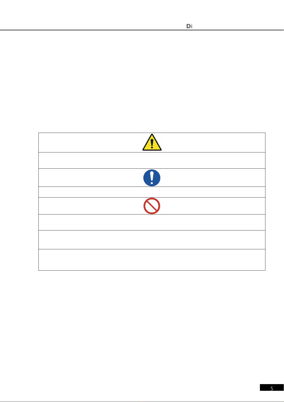
SAFETY INFORMATION
SAFETY INFORMATIONSAFETY INFORMATION
SAFETY INFORMATION ..
....
..……………
…………………………
………………………………………………………………………………………
……………………………………………………………………………………………………………………………………………………
…………………………………………………………………………
2
22
2
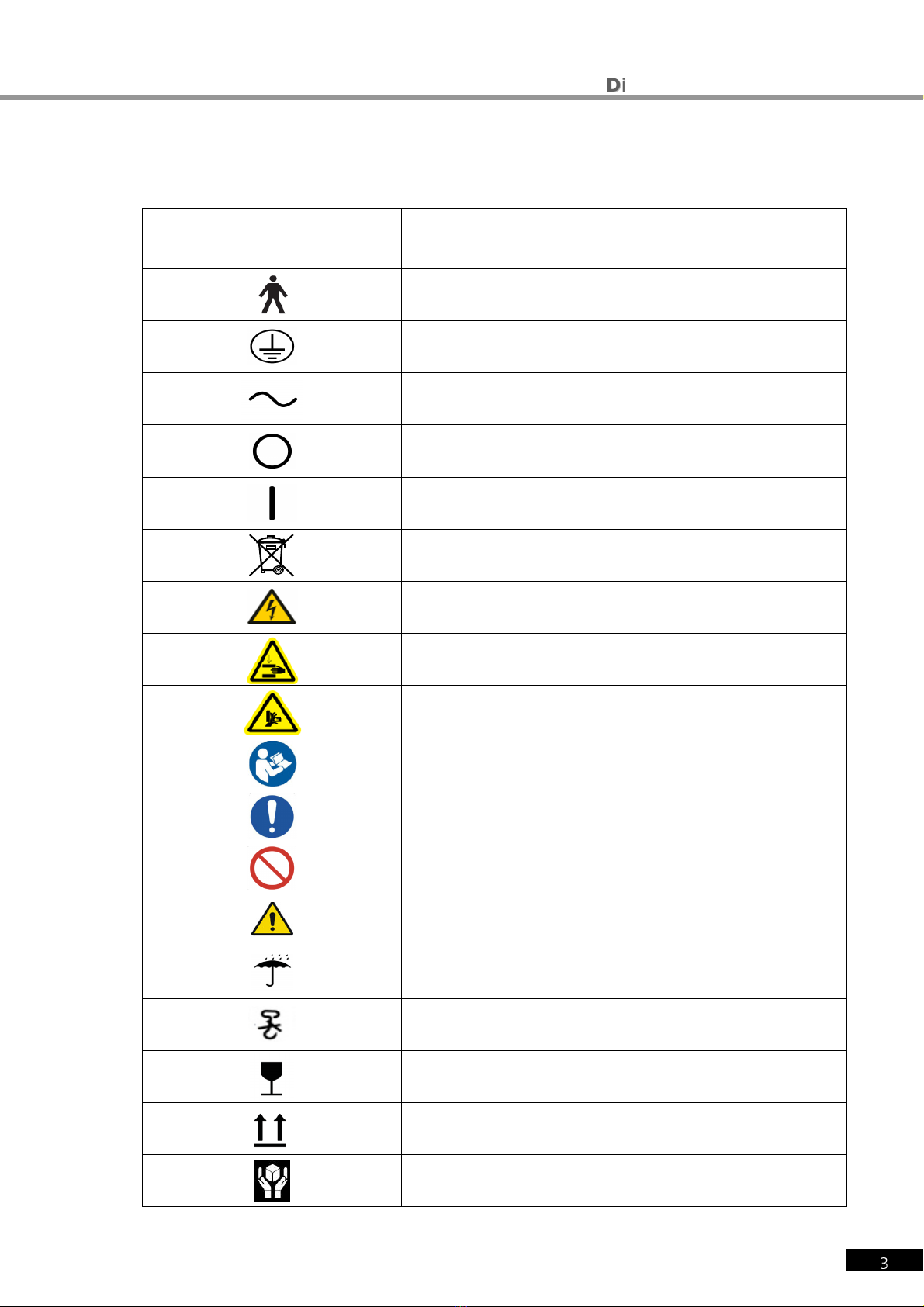
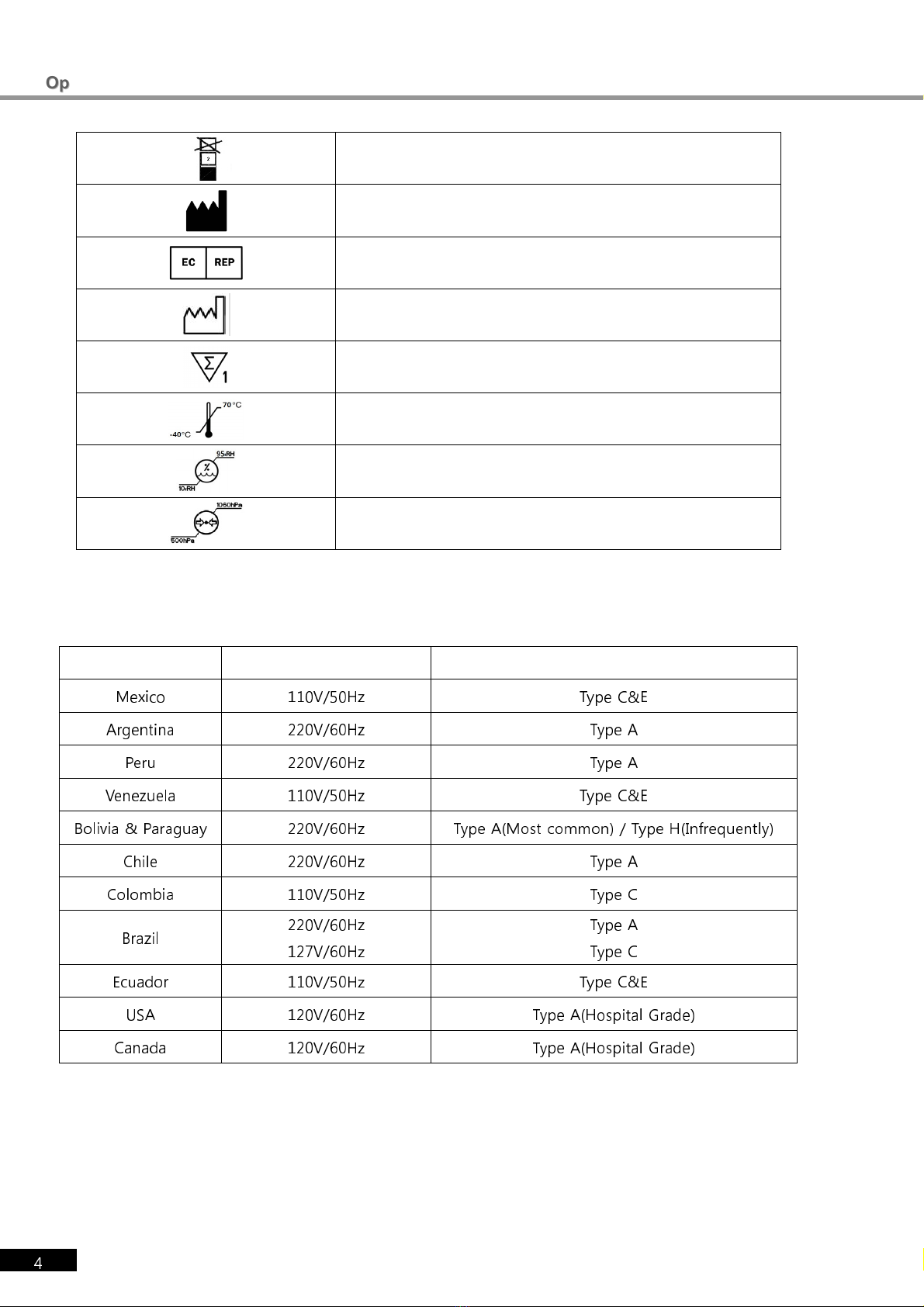
SYMBOLS
SYMBOLSSYMBOLS
SYMBOLS…………………
……………………………………
…………………....
........
....……………
…………………………
……………………………………………………………………………
………………………………………………………………………………………………………………………………
…………………………………………………………………
……
………
…………
……
3
33
3
GENERAL SAFETY INFORMATION
GENERAL SAFETY INFORMATIONGENERAL SAFETY INFORMATION
GENERAL SAFETY INFORMATION ……………………………………………………………………………
…………………………………………………………………………………………………………………………………………………………
……………………………………………………………………………
5
55
5
1.
1.1.
1.
Characteristics
CharacteristicsCharacteristics
Characteristics
................................
................................................................
................................................................
................................................................
................................................................
................................................................
...............................................
..............................
...............
10
1010
10
2. Notice for Use
2. Notice for Use2. Notice for Use
2. Notice for Use
................................
................................................................
................................................................
................................................................
................................................................
................................................................
...............................................
..............................
...............
11
1111
11
3. Prerequisite for safety
3. Prerequisite for safety3. Prerequisite for safety
3. Prerequisite for safety
................................
................................................................
................................................................
................................................................
................................................................
................................................................
.....................................
..........
.....
13
1313
13
4. Designations and Functions of Each Parts
4. Designations and Functions of Each Parts4. Designations and Functions of Each Parts
4. Designations and Functions of Each Parts
................................
................................................................
................................................................
................................................................
.........................................
..................
.........
14
1414
14
4.1 Body of EDR 7800 (Ref.Body) ................................................................................... 14
4.2 Operation Panel....................................................................................................... 15
4.3 Junction Box........................................................................................................... 17
4.4 Accessaries ............................................................................................................ 18
4.4.1
Ref. Body ...................................................................................................................................................................... 18
4.4.2
Operation Panel ........................................................................................................................................................ 19
4.4.3
JUNCTION BOX ......................................................................................................................................................... 19
4.4.4
Converter Box ............................................................................................................................................................. 20
4.5 How to install EDR 7800 ........................................................................................... 21
4.5.1
Notice to install EDR 7800 ................................................................................................................................... 22
5. Basic operation
5. Basic operation5. Basic operation
5. Basic operation
................................
................................................................
................................................................
................................................................
................................................................
................................................................
.............................................
..........................
.............
23
2323
23
5.1 How to conrtol Key pad button on OP PANEL.............................................................. 23
5.2 How to control touch screen monitor.......................................................................... 25
6. Test Mode
6. Test Mode6. Test Mode
6. Test Mode................................
................................................................
................................................................
................................................................
................................................................
................................................................
.....................................................
..........................................
.....................
29
2929
29
6.1 Why does need Test Mode? ...................................................................................... 30
6.2 Test Mode and Results Copy..................................................................................... 30
6.3 Use of PRESET and AUX OFF Mode........................................................................... 31
6.4 Test of Far Vision and Near Vision ............................................................................. 32
7. Communication with Various Vision Test Devices
7. Communication with Various Vision Test Devices7. Communication with Various Vision Test Devices
7. Communication with Various Vision Test Devices
................................
................................................................
................................................................
................................................................
................................
34
3434
34
7.1 Option setting for Chart Projector (ECP- 5400)............................................................. 34
7.2 Option setting for Auto Ref/ Keratometer (ERK- 7800).................................................. 34
7.3 Load and Save the data of Auto Ref / Keratometer (ERK- 7800) ................................... 34
7.4 Make Use of Built- In Database.................................................................................. 36
8. Choose Menu
8. Choose Menu8. Choose Menu
8. Choose Menu
................................
................................................................
................................................................
................................................................
................................................................
................................................................
................................................
................................
................
37
3737
37
8.1 TEST RESULT ......................................................................................................... 37
8.2 SYSTEM CONFIG..................................................................................................... 40
8.2.1
How to control the b tton key .......................................................................................................................... 40
8.2.2
Introd cing each page ........................................................................................................................................... 41