eZway Stand Aid Specifications

EZ Way Stand Aid
400 lb. Capacity
Form 2-198
Rev. 8/15/18
Operator’s Instructions
EZ Way, Inc.
PO Box 89
Clarinda, IA 51632
1-800-627-8940
www.ezlifts.com
WARNING: Cancer and Reproductive Harm - www.P65Warnings.ca.gov.

The affordable, durable EZ Way Stand Aid actively engages the patient in the standing process, thus reducing
the need for caregiver assistance. Its ability to fit through narrow doorways and 400 lb. safe working load makes it
an excellent wheelchair alternative for convenient patient transfers. Call EZ Way at 1-800-627-8940 to schedule
a product demonstration.
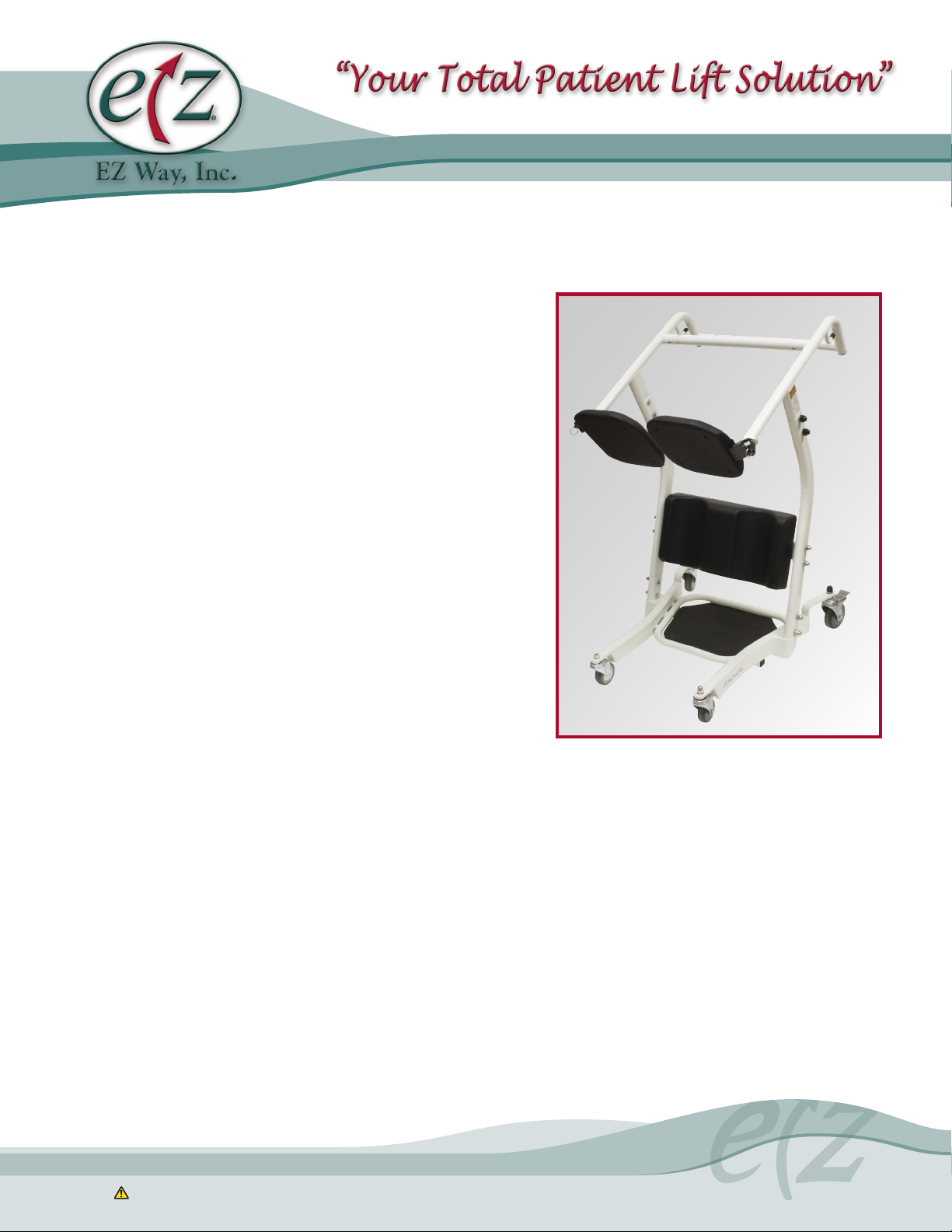
The EZ Way Stand Aid is a transfer assist unit which keeps residents active and engaged in the transferring
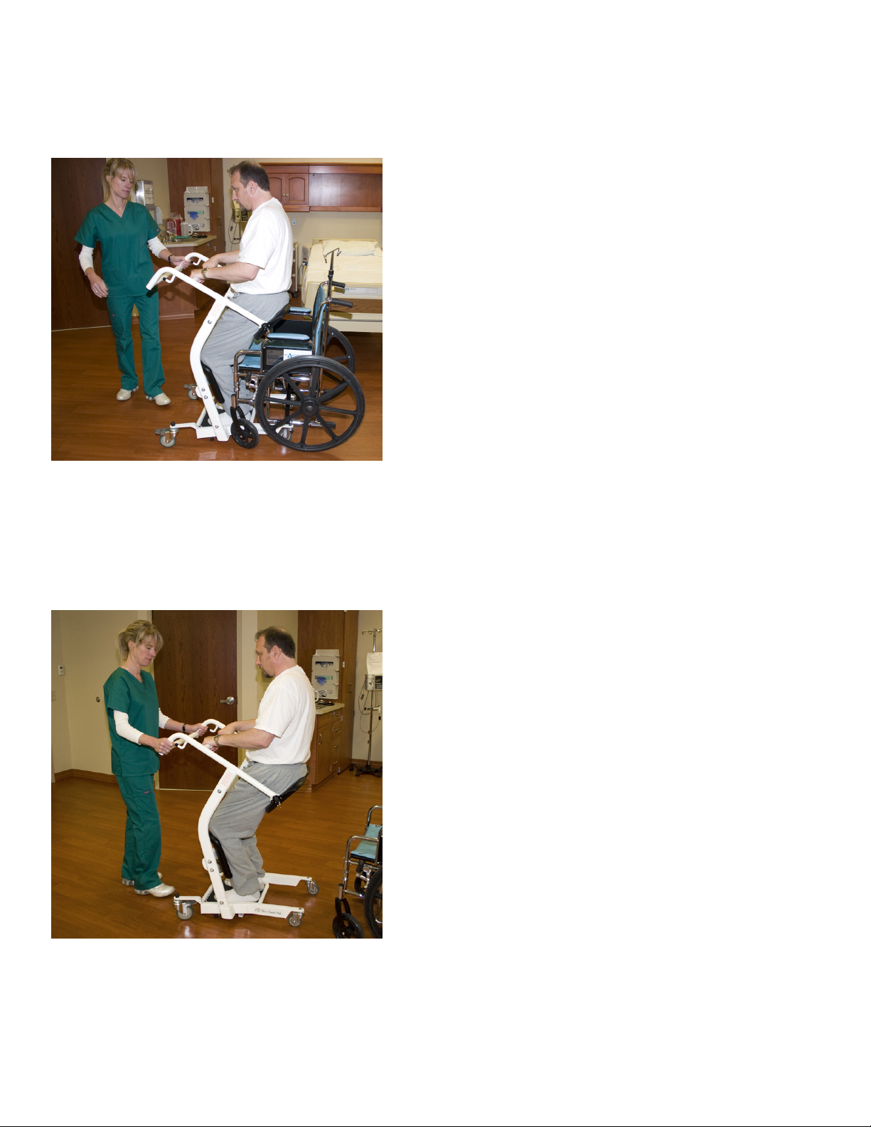
process. Transfers are quick and require minimal caregiver assistance. Users simply grasp the middle bar and pull
themselves up. A padded split seat swings out for loading or unloading then swings back to form a comfortable,
secure seat for transport. It is an excellent alternative to a wheelchair for easier commode access.
For safe operation of the EZ Way Stand Aid, operators should read through this manual, complete the
competency checklist, and practice on fellow staff members before use with patients.
Safety Notes
The EZ Way Stand Aid is a manual standing aid to allow patients to assist themselves in preparation for
transferring. Patients qualified to use the EZ Way Stand Aid should have adequate arm strength to pull
themselves upward and enough leg strength to support their own weight. Patients who meet this criteria and
have difficulty walking will find the EZ Way Stand Aid a useful and safe transferring device. The Stand Aid
is positioned between a traditional walker and electric stand assist lift in terms of function. Once the resident
has positioned themselves on board, the split seat can easily be placed securely and allow the resident to sit
comfortably while a caregiver performs the transfer. For residents lacking the strength to assist themselves, an EZ
Way Smart Stand®or EZ Way Smart Lift®is recommended.
The EZ Way Stand Aid is capable of the following transfers when used according to the instructions:
1) Bed to Chair/Wheelchair
2) Bed/Chair/Wheelchair to commode
3) Room to Room
These instructions should be kept with the EZ Way Smart Stand Aid at all times. Instructions can also be
downloaded from EZ Way’s website www.ezlifts.com.
2
Never attempt to transfer a patient whose
weight exceeds 400 lbs.
WARNING:
Failure to use this device according to
instructions may cause serious injury.
WARNING:
Do not leave a patient unattended during
transfer.
WARNING:
Assembly and Safety Precautions
Only qualified caregivers familiar with the proper use of the EZ Way Stand Aid should attempt to transfer
patients.
1) Patients unable to pull themselves upright and support their own weight should not be transferred with an EZ
Way Stand Aid.
2) Never attempt to transfer a patient whose weight exceeds the safe load limit.
3) Prior to a transfer, check the EZ Way Stand Aid to ensure all components are properly and securely assembled
and in working order.
4) Do not leave a patient unattended during any part of the transfer.
Maximum safe working load limit is 180kgs / 400lbs.
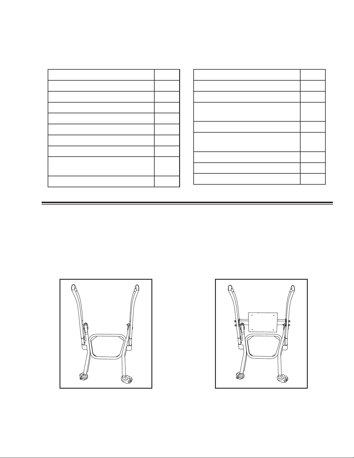
Assembly Instructions
Prior to assembly unload shipping carton and check all parts. Contact EZ Way if parts are missing.

3
Parts Included
Step-by-Step Assembly
1) Install 2 PC long-curved legs on base with
casters. Use 4 carriage bolts, threads facing out.
Install washer, lock washer and acorn nut, then
tighten. Place black acorn nut cover on nut.
2) Add a shin pad backing plate. Install bolts as in
Step 1.
Part Description QTY
Handrail Tube 2
Shin Pad Backing Plate 1
Shin Pad 1
Seat Pad 2
L Tube 2
Leg 2
Lock for Seat Pad 2
Carriage Bolts/Nuts/
Flat & Lock Washers/Black Caps 12
1/2" Hex Screws 4
Part Description QTY
Socket Head Cap Screws/Washers 2
Base with Casters 1
1-1/4" Screws & 1/4" Flat Washer
for Shin Pad 4
Rubber Cap for Seat Lock 2
5/16" Hex Bolt/
Flat & Lock Washers 2
Brass Bushings 2
Glue for Brass Bushings 1
Seat Locks 2
Tools Needed
5/16" Allen wrench, 5/32" Allen wrench, 11/16" Open or box wrench
Step 1: base with casters
ASSEMBLY INSTRUCTIONS
1914
Size:210x285mm Face Side
Step 2: install 2PC long curved legs Step 3: add 1PC leggings baffle
Step 4: add baffle pad in the top of
the legging baffle
Step 5: take 2PCS handrail tubes &
L tubes
Step 6: assembly handrail tubes with
L-shaped tubes
Step 1: base with casters
ASSEMBLY INSTRUCTIONS
1914
Size:210x285mm Face Side
Step 2: install 2PC long curved legs Step 3: add 1PC leggings baffle
Step 4: add baffle pad in the top of
the legging baffle
Step 5: take 2PCS handrail tubes &
L tubes
Step 6: assembly handrail tubes with
L-shaped tubes

4
3) Add shin pad to the top of the backing plate.
Use 4 Allen screws with washers.
5) Assemble base with two legs and L tubes. Install
bolts as in Step 1.
4) Assemble handrail tubes with L-shaped tubes
using 4 small Allen screws.
Step 1: base with casters
ASSEMBLY INSTRUCTIONS
1914
Size:210x285mm Face Side
Step 2: install 2PC long curved legs Step 3: add 1PC leggings baffle
Step 4: add baffle pad in the top of
the legging baffle
Step 5: take 2PCS handrail tubes &
L tubes
Step 6: assembly handrail tubes with
L-shaped tubes
Step 1: base with casters
ASSEMBLY INSTRUCTIONS
1914
Size:210x285mm Face Side
Step 2: install 2PC long curved legs Step 3: add 1PC leggings baffle
Step 4: add baffle pad in the top of
the legging baffle
Step 5: take 2PCS handrail tubes &
L tubes
Step 6: assembly handrail tubes with
L-shaped tubes
Size:210x285mm Back Side
ASSEMBLY INSTRUCTIONS
1914
Step 7: Assembly base with two legs
and L tubes.
Step 8: Lock fasteners for installing
L tubes.
NO.
1
2
3
4
5
6
DESCRIPTION
Handrail tube Lock for cushion
Hex screws
Casters
Base
Socket head cap screws/washers
Carriage Bolts\Nuts\Washers\Black Caps
Legging baffle
Shin pad
Cushion
L tube
Leg
2 2
2
4
4
1
12
2
2
2
1
1
QTY
Step 9: Insert the seat pad with lock
Step 10: install all parts completedly.
NO.
7
8
9
10
11
12
DESCRIPTION QTY
6) Place 2 drops of glue on inside brass bushing and
push onto bushing post.
7) Insert the seat pad with lock. Proper lock
position is with seat down. Use Allen screw and
washer to install lock. Place black cap on screw.
Repeat for other locking seat pad.
8) Tighten all parts completely.
NOTE: DOUBLE CHECK ALL ASSEMBLIES
FOR TIGHTNESS AND READ OPERATING
INSTRUCTIONS CAREFULLY PRIOR TO USE
Size:210x285mm Back Side
ASSEMBLY INSTRUCTIONS
1914
Step 7: Assembly base with two legs
and L tubes.
Step 8: Lock fasteners for installing
L tubes.
NO.
1
2
3
4
5
6
DESCRIPTION
Handrail tube Lock for cushion
Hex screws
Casters
Base
Socket head cap screws/washers
Carriage Bolts\Nuts\Washers\Black Caps
Legging baffle
Shin pad
Cushion
L tube
Leg
2 2
2
4
4
1
12
2
2
2
1
1
QTY
Step 9: Insert the seat pad with lock
Step 10: install all parts completedly.
NO.
7
8
9
10
11
12
DESCRIPTION QTY

5
Seat usage instructions
The two black molded seat units can be rotated
upwards to allow for patient loading. Once the
patient is in an upward standing position the split
seats must be lowered down to form a complete
two-sided seat. Always make sure each of the two
seat components are properly lowered and locked,
forming a complete seat prior to having the patient
sit down.
Instructions for use and transport
1) Raise the two split seat units up and parallel to
the side of the EZ Way Stand Aid as shown
below.
2) Have the patient positioned at the edge of the
surface and move the EZ Way Stand Aid in front
of the patient so that their feet are firmly on the
platform and knees/shins are in contact with the
two cupped knee/shin pads as shown below.
3) Lock the casters by stepping on the caster clip
and pushing down as shown below.
4) Have the patient grasp the cross bar closest to
them and using their own strength, pull
themselves up into a standing position firmly on
the platform as shown below.
5) Lower both of the split seat units down into
position to form a complete seat as shown below.
Confirm seat locks are engaged.

6
6) Have the patient lower themselves down onto
the seat while keeping their knees/shins in the
knee/shin pads and while still holding the cross
bar with both hands as shown below. Make sure
both seat locks are locked in place.
7) Unlock the casters and place both hands on the
cross bar furthest from the patient and move the
EZ Way Stand Aid to the new surface. Make sure
the patient is secure and in proper position as
described in Step 6 above prior and during
transfer as shown below.
Once the EZ Way Stand Aid has been positioned
against the new surface, the following steps are
required
1) Position the EZ Way Stand Aid against the new
surface ensuring the patient will be in a position
to sit down firmly and safely on the new surface.
2) Lock the casters.
3) Have the patient pull themselves back up to a full
standing position.
4) Unlock and raise the two split seat units up to
a parallel position to allow the patient to lower
themselves.
5) Stand beside the patient as they lower themselves
down onto the new surface.
6) Make sure the patient is safely positioned then
unlock the casters and move the EZ Way Stand
Aid to storage.

7
Accessories
The EZ Way Stand Aid is designed to fully support a seated patient for transfer. For patients requiring some upper
body support or additional security, a safety belt may be used. Either the Standard or Extra Large seat belt is
designed to work with the EZ Way Stand Aid. Please see the pictures below for the use of these slings:
Maintenenance
The EZ Way Stand Aid is a manual unit and therefore requires minimum maintenance on an ongoing basis.
However to ensure safety and proper use the following steps should be taken on a monthly basis:
1) Check all bolt/nut assemblies to make sure they are tight and no wear and tear is evident. Replace
and tighten any worn assemblies prior to using the EZ Way Stand Aid.
2) Check the two seat assemblies to make sure they are not worn or damaged and that the bolts are tight.
Replace any worn or damaged seat components prior to using the EZ Way Stand Aid.
3) Check the casters to make sure they are in working order and are secured firmly to the EZ Way Stand Aid.
Replace any worn or damaged casters prior to using the EZ Way Stand Aid.
LIMITED WARRANTY: EZ WAY STAND AID
The product you purchased is guaranteed by EZ Way, Inc. to be free from defects in material and workmanship under normal use and
service. The warranty period for this product is twenty four (24) months from the date of purchase by the original purchaser. EZ Way
agrees to repair or replace this product, at our option and at no charge, within the warranty period and proven by EZ Way’s consent to
be defective. For warranty service, please contact EZ Way, Inc. at 800-627-8940. To ensure the best service to our customers, EZ Way
requests the following information to be included with the returned unit:
1) Model Name/Number and Serial Number attached on the packaging.
2) A detailed description of the problem and its symptoms.
This warranty shall not apply to any product which has been repaired or altered in any way so as, in our judgment, to affect its
functionality and durability, nor to any product subject to abuse, misuse, negligence or accident, improper maintenance, improper
installation, nor to any product used with other parts, components and /or accessories with quality and/or specifications incompatible with
this product. This warranty shall also be voided if any required periodic maintenance, if applicable, has not been properly performed on
this product.

8
EZ Way Stand Aid Competency Checklist
Purpose: To assist in the proper training of operating the EZ Way Stand Aid.
Staff Name: Date: Observed by:
Yes No
a) Demonstrate how to approach the patient with the unit and direct them to place their feet
on the footplate and their hands on the grasp bar.
b) Demonstrate how to direct the patient to raise themselves high enough so that the seat pads
can be swung into place below the patient’s buttocks.
c) In seating the patient onto a surface such as a wheelchair or toilet, demonstrate how to
direct the patient to raise themselves off the seat pads and how to unlock the seat locks.
d) Demonstrate how to swing the seat pads out from under the patient while the patient is
above a seating surface and direct them to seat themselves.
e) State the weight capacity of the unit.
Table of contents
Other eZway Medical Equipment manuals
Popular Medical Equipment manuals by other brands

Activ8rlives
Activ8rlives Pulse Oximeter2 Bluetooth manual

Agilent Technologies
Agilent Technologies PageWriter 10 Quick reference guide

bort medical
bort medical MalleoXpress quick guide

Anetic Aid
Anetic Aid AT4 Instructions for use

Welch Allyn
Welch Allyn Ear Wash System Directions for use

ResMed
ResMed AirFit F20 user guide