COLOUR SPOT- Discharge lamp
7/9
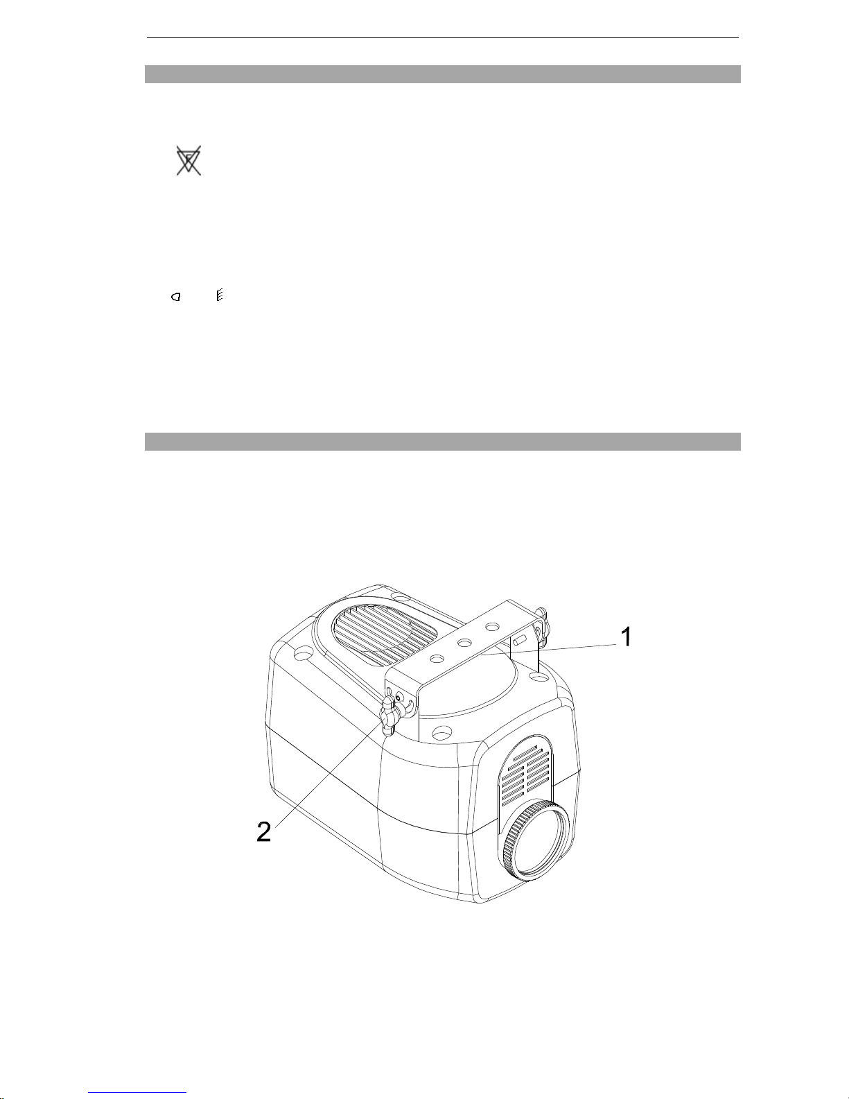
10 FOCUS
It ispossibleto movethe lensfor focusing the projector, simplytwistthe lenstubeclockwiseor
anticlockwise to achievefocus.
11 MAINTENANCE
Ifthe projectorslensbecomesdamaged or broken it should be replaced.
Ifthe lamp becomesdamaged or deformed in any way it must be replaced.
If the lightfromthelampappearsdimthiswouldnormallyindicate thatitisreaching the end ofitslife
and itshould be changed at once, oldlampsrun to theextremity oftheirlifecan explode.
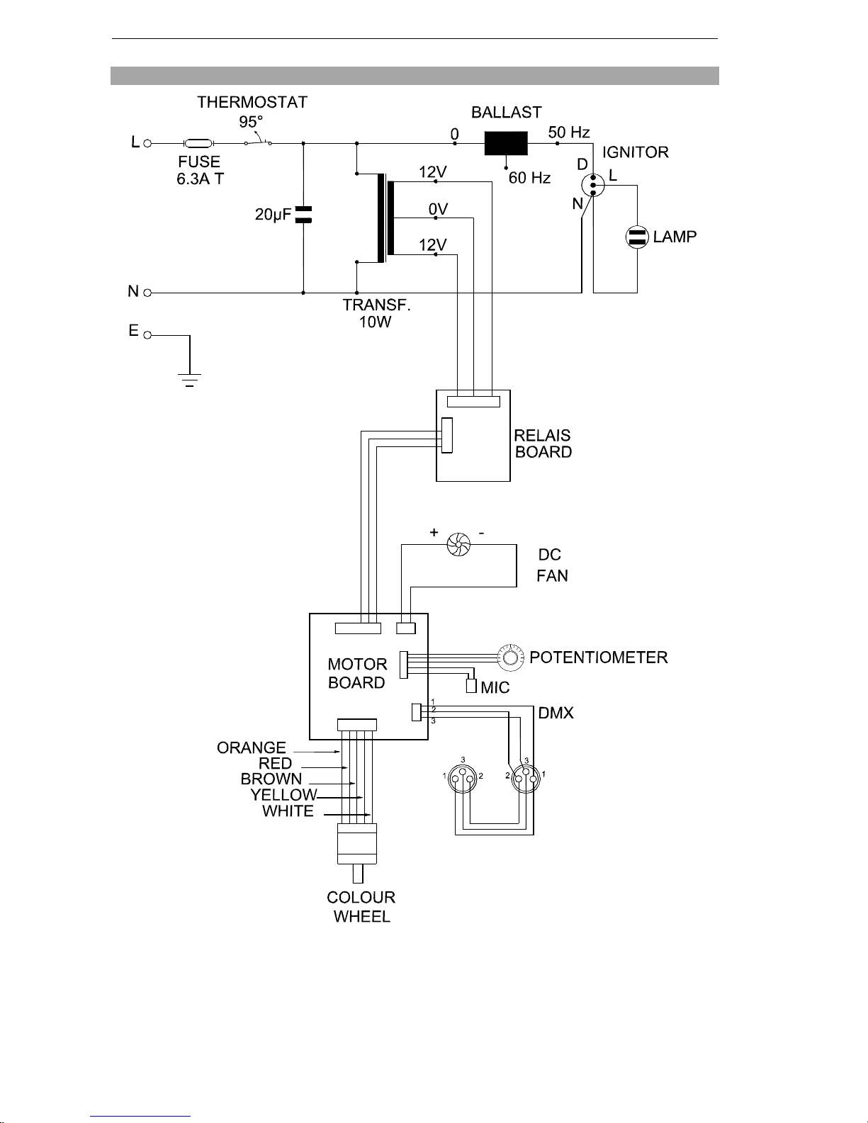
Ifthe projector doesnot function, check the fusesby the power socket onthe projector, they should
only be replaced by fuses ofthe samevalue asthat marked beside the fuse holder. On the electronics
card (pcb) inside the projector isafuserated at 4A F(fastblow), shouldthisbe damaged call a
qualified technician before replacement.
The Colour Spotalsohasathermalprotection device that willswitch off the projector incaseof
overheating, shouldthisoperate, check that the fan isnot blocked, and ifitisdirty clean it before
switching on the projector again.
Check that the fan isoperational, if not callaqualified technician.
12 KEEPING THE PROJECTOR CLEAN
To ensure the reliabilityof the projector itshouldbe kept clean. It isrecommended that the fan should
be cleaned every15 days.The lens,mirrorand dichroic colour filtersshouldalsobe regularlycleaned
to maintainan optimumlight output.Do not useany type ofsolvent on the mirror or dichroiccolour
filters.
13 TROUBLESHOOTING
PROBLEMPOSSIBLE SOLUTION
TheprojectordoesnotstartCheck thefusesbythepowerconnector.
Thelampcomeson buttheprojector doesnot
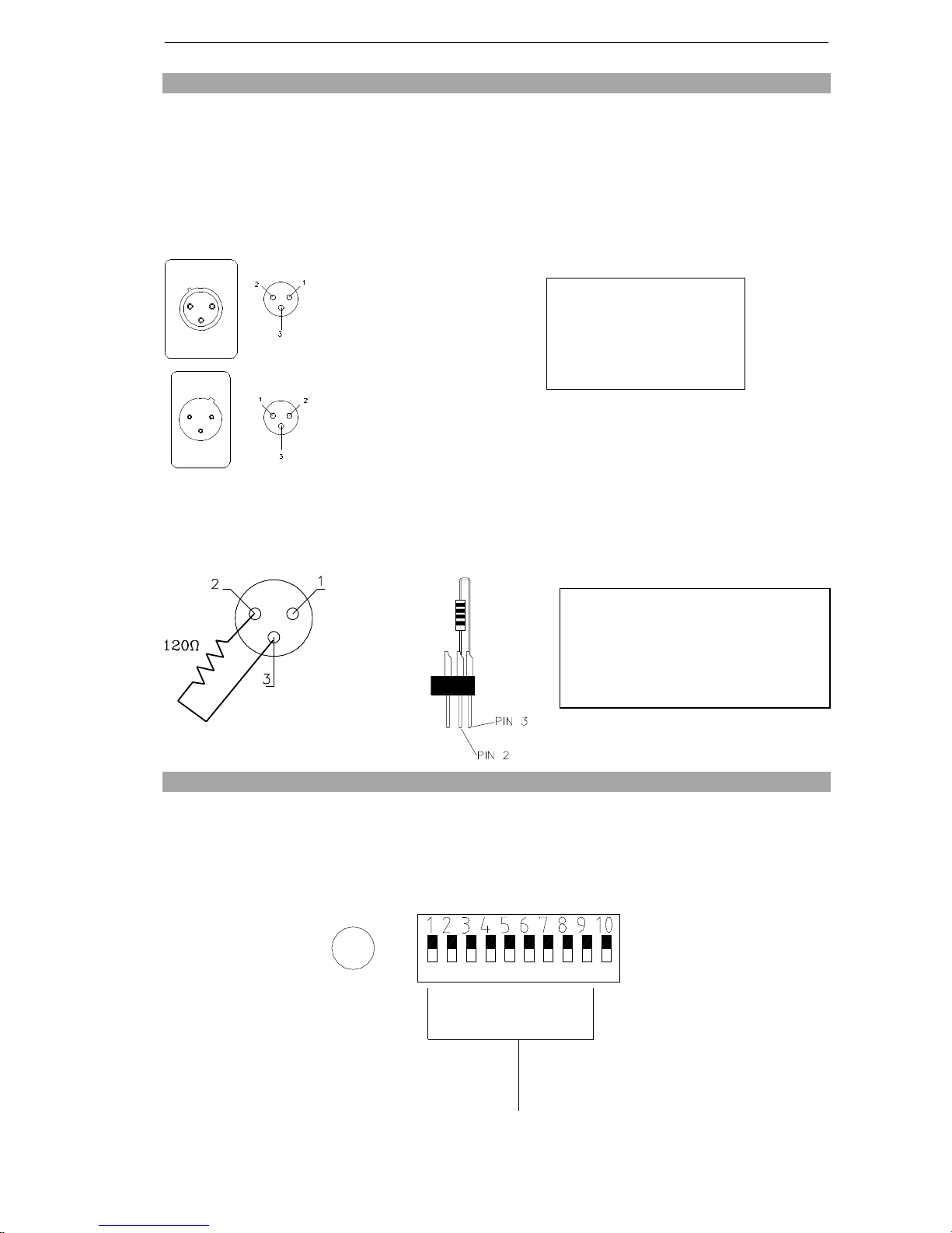
respond tothecontroller Check thedigitalstartaddress (section 07) and check
thewiringofthecontrolcable(section06).
TheprojectoronlyfunctionsintermittentlyCheck thefanisworkingandnotdirty.
TheprojectedimageappearstohaveahaloCheck thelampisinstalledcorrectly(section03).
Thebeam appearsdimThelampmaybeattheend ofitslifeand shouldbe
replaced. Checktheopticsareclean.
Any other maintenance should onlybe performed bya qualified person.