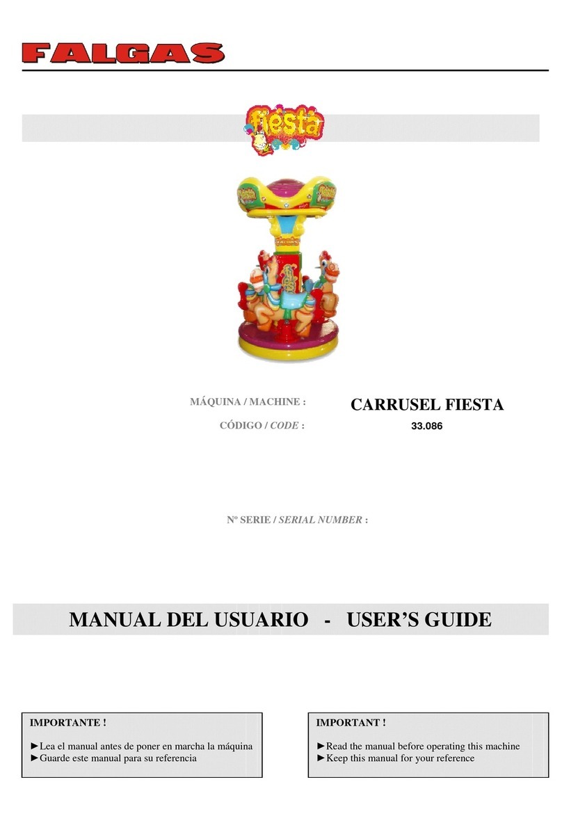
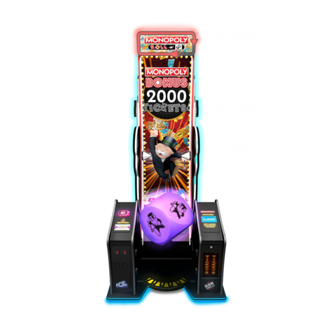
F.Y.C KIDDY RIDE Jumping Frog FC-094 User manual


Page 1
Contents

Page 5
Contents

Page 6
Contents

Page 7
Contents

Page 8
Contents

OPERATION MANUAL - SILVER CONTROL & MUSIC BOX
CONTENT
1. Function Introduction
2. Specification Introduction
3. Function Description:
Control Panel
Connect Panel
SD CARD Set Up Introduction
Music Installation
4. Attention
5. Rear Panel Pin Assignment

1. Function Introduction
The equipment is for Kiddy Ride machine only.
Function and feature:
1. 15W sound-stereo,and volume adjustment.
2. Set up the meter value by coin or play-time.
3. Multiple coins value set up for game-play.
4. Multiple times value set up for game-play.
5. AC Power 10A fuse、DC Power 5A fuse protection.
6. Use the mechanical-meter to count the coins or game-play.
7. The SD Card save music and may change the music by operator.
8. Power and Action led light directive for working.

2. Specification Introduction
MUSIC BOX
Specification
AC input
AC 85V~265V 50/60Hz
AC output (motor)
AC110 / AC220V , 10A
DC12V output
4A (TOTAL)
Speaker
15W / 8ΩSTERO
Music Storage
SD CARD (Up To 8G)
Music Format
MP3
AC Fuse
10A
DC Fuse
4 A
Weight
1.5 KG
Dimension
D:187mm x W:208mm x H:58mm

Main Unit
Specification
Dimension
D:170mm x W:168mm x H:54mm
Connect Unit
Specification
Dimension
D:90mm x W:208mm x H:58mm

3. Function Description:
Control Panel
1.
VOLUME
volume adjustment
2.
FUNCTION
SETTING
1
2
3
4
5
○
Coin Start
×
Button Start
○
Coin Record
×
Coin Unrecorded
×
Coin Selector- NO
○
Coin Selector- NC
○
Testing Mode
×
Normal Mode
○
Coin Counter
×
Game-Play Counter
Testing Mode:The cycle work 60 sec and then stop 60 sec.
Normal Mode:The business mode.
Coin Counter:The meter work for every coin. (1Coin 1 Play)
Game-Play Counter:The meter work for every game-play.
3.
COIN
Turn the knob to direct number and the function as follow:

SETTING
Position
Function
1
1Coin 1 Play
2
2 Coins 1 play
3
3 Coins 1 play
4
4 Coins 1 play
5
5 Coins 1 play
6
6 Coins 1 play
7
7 Coins 1 play
8
8 Coins 1 play
4.
TIME
The
Game-Play
time setup.
Turn the knob to direct number and the function as follow:
Position
Function
1
The Game-Play time:30 sec.
2
The Game-Play time:60 sec.
3
The Game-Play time:90 sec.
4
The Game-Play time:120 sec.
5
The Game-Play time:150 sec.
6
The Game-Play time:180 sec.
7
The Game-Play time:210 sec.
8
The Game-Play time:240 sec.
9
The Game-Play time:270 sec.
10
The Game-Play time:300 sec.
5.
AC Fuse
10A
6.
DC Fuse
4 A
7.
START
BUTTON
Press the button for game start.
8.
STOP
BUTTON
Press the button for game stop.

9.
METER
The mechanical-meter to count the coins or game-play.
10
SD Card
For SD Card install and work.
11.
POWER
Power led light directive for working.
12.
ACT
ACT led light directive for working.
***NOTE***
For each function change, the unit must reboot (power off/on) and the
function is working.

Connect Panel
J3 12-PIN
LED LAMP
*NOTE 1
1
GND
GND
2
The game-playing and DC power output.
DC 12V
3
GND
GND
4
The game-playing and DC power output.
DC 12V
5
GND
GND
6
The game-playing and DC power output per
0.5 sec.
DC 12V
7
GND
GND
8
The game-playing and DC power output per
0.5 sec.
DC 12V
9
GND
GND
10
The unit power-on and DC power output.
DC 12V
11
GND
GND
12
The unit power-on and DC power output.
DC 12V
J46-PIN
COIN
1
Coin Power VCC
DC 12V
2
Coin Power GND
GND
3
Coin Signal
SIGNAL
4
Start-Button light GND
GND
5
enable VCC
DC 12V
6
NO USE
NO USE
J5 8-PIN
EFFECT SWITCH
1
Start-Button
SW-1-NO
2
Start-Button
SW-1-COM

3
Effect-Button -1-
SW-2-NO
4
Effect-Button -1-
SW-2-COM
5
Effect-Button -2-
SW-3-NO
6
Effect-Button -2-
SW-3-COM
7
NO USE
NO USE
8
NO USE
NO USE
J6 8-PIN
AC INPUT
1
AC INPUT GND
AC INPUT
85V~265V
MAX 10A
2
AC INPUT GND
3
AC INPUT L
4
AC INPUT N
5
AC INPUT L
6
AC INPUT N
7
AC INPUT L
8
AC INPUT N
J7 4-PIN
AC OUTPUT
1
AC OUTPUT N
AC
OUTPUT
85V~265V
2
AC OUTPUT GND
3
AC OUTPUT L
4
AC OUTPUT GND
J8 6-PIN
MOTOR AC POWER
1
MOTOR AC OUTPUT L
110V/220V
MAX 10A
2
MOTOR AC OUTPUT L
3
MOTOR AC OUTPUT N
4
MOTOR AC OUTPUT N
5
MOTOR AC OUTPUT GND
6
MOTOR AC OUTPUT GND
J9 4-PIN
RS 232
1
RS232 COM
2
RS232 TX
3
RS232 COM
4
RS232 RX
J10 4-PIN
SOUND
1
SPEAKER R+
15W/8Ω
2
SPEAKER R-
3
SPEAKER L-
4
SPEAKER L+

J11 3-PIN
LIMIT SWITCH
1
+12v
2
SIGNAL
3
GND
J12 2-PIN
MOTOR AC LAMP
1
MOTOR AC LAMP OUTPUT L
110V/220V
2
MOTOR AC LAMP OUTPUT N
*NOTE 1:DC 12V power output maximum is 4A。

SD CARD Set Up Introduction
Tools:Flathead screwdriver、SD CARD。
Install:
Insert the SD CARD into the slot then use the flathead screwdriver to
press it.

Press to bottom and the SD CARD stuck. The install finished.
Uninstall
Use the flathead screwdriver to press the SD CARD to bottom. And the
slot will release the SD CARD.
Remove the flathead screwdriver and the SD CARD eject. And then take
out the SD CARD.

Music Installation
1. Set up the folders are named as below in the SD CARD.
2. Saving music files to the folder as your require and file type is .mp3.
3. MUSIC:The game-play mode use and play by turns.
EFFECT1:Press Effect-Button -1-, the mode use and play by turns.
EFFECT2:Press Effect-Button -2-, the mode use and play by turns.
4. Attention
** The equipment for maintenance staff operate only.
** Power off to remove the Main Unit.
** Please follow the operation manual to operate the equipment.

Rear Panel Pin Assignment
AC in
85~265 V
AC out
110/220 V
Motor AC out
110/220 V
DC 12V out
DC 12V out
DC 12V out
+
_
Coin Selector Power (DC 12V)
Coin Selector Impulse
Coin Selector Ground
+
+
_
_
Black
Pink
Yellow
Black
Orange
Red
Black
Black
Red
White
Normally Open
Normally Closed
White Gray
Blue
Speaker L
Speaker R
Black
Black
Green
+
_
_
+
Purple
Effcet Button 2
Effcet Button 1
Start Button
_
_
_
+
+
+
Black
Black
Black
Brown
Gray
Table of contents