F5 Paint Shaker Quick guide

F5 Paint Shaker
877-862-7049 www.F5PaintShaker.com
1.
2.
3.
4.
5.
6.
10.
7.
11.
8. 9.
17.
18.
13.
12.
19.
22.
21.
20.
26.
30.
27.
23.
24.
25.
20.
23.
24.
25.
14.
15.
16.
14.
15.
16.
Front
Left
Back
Right
Back
Left
Front
Right
29.
28.
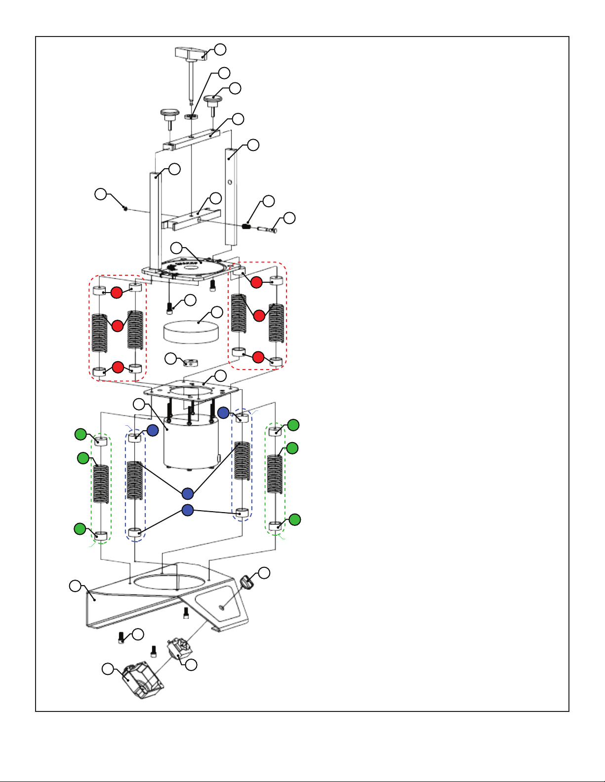
Holding Down Bolt
Jam Nut
Fixing Bolt
Adapter Plate
Right Side Support Plate
Left Side Support Plate
Spindle
Batten
Pull Off Spring
Lock Pin
Support Plate for Plate Can
M8 Inner Hexagon Screw
Bonnet
Fixed Block for Spring #3
Spring #3
Fixed Block for Spring #3
Eccentric Wheel
Fitting Plate for Motor
Motor
Fixed Block for Spring #2
Spring #2
Fixed Block for Spring #2
Fixed Block for Spring #1
Spring #1
Fixed Block for Spring #1
Knob for Timer
Timer
Timer Cover
M5 Screw
Base
1.
2.
3.
4.
5.
6.
7.
8.
9.
10.
11.
12.
13.
14.
15.
16.
17.
18.
19.
20.
21.
22.
23.
24.
25.
26.
27.
28.
29.
30.
F5 Paint Shaker Parts Diagram:
F5 Paint Shaker
877-862-7049 www.F5PaintShaker.com

1. Make sure that are in which you are operating the machine has adequate ventilation.
2. If the machine’s electrical cords are damaged (frays, etc.), do not use the machine.
3. Operate the machine only on solid, level, open-area surfaces.
4. Check for leaks or deformations in the can before shaking. Do not shake a damaged
can, and check regularly for damages during the mix cycle.
5. Do not leave the room while the machine is in use.
6. Unplug the machine while not in use or while you are working on it.
Before You Begin: Safety Instructions
•³⁄16” hex key
•⁵⁄32” hex key
•Channel-lock pliers
Tools Needed for Installation of Springs
1. Unpack machine and all parts and places on solid, level, open-area surface.
2. Ensuring that the side hole is located on the right side, fasten the bracket assembly
to the platform. (Fig. A) If the bracket assembly is not pre-assembled, please follow
the diagrams below (Fig. B) to assemble it.
3. Plug in the cord, making sure it is not in the path of any obstructions.
4. Familiarize yourself with the operating instructions, and place them where you can
see them while operating the machine.
Initial Machine Setup
Fig. A:
F5 Paint Shaker
877-862-7049 www.F5PaintShaker.com
Hole Located
on Right Side

F5 Paint Shaker
877-862-7049 www.F5PaintShaker.com
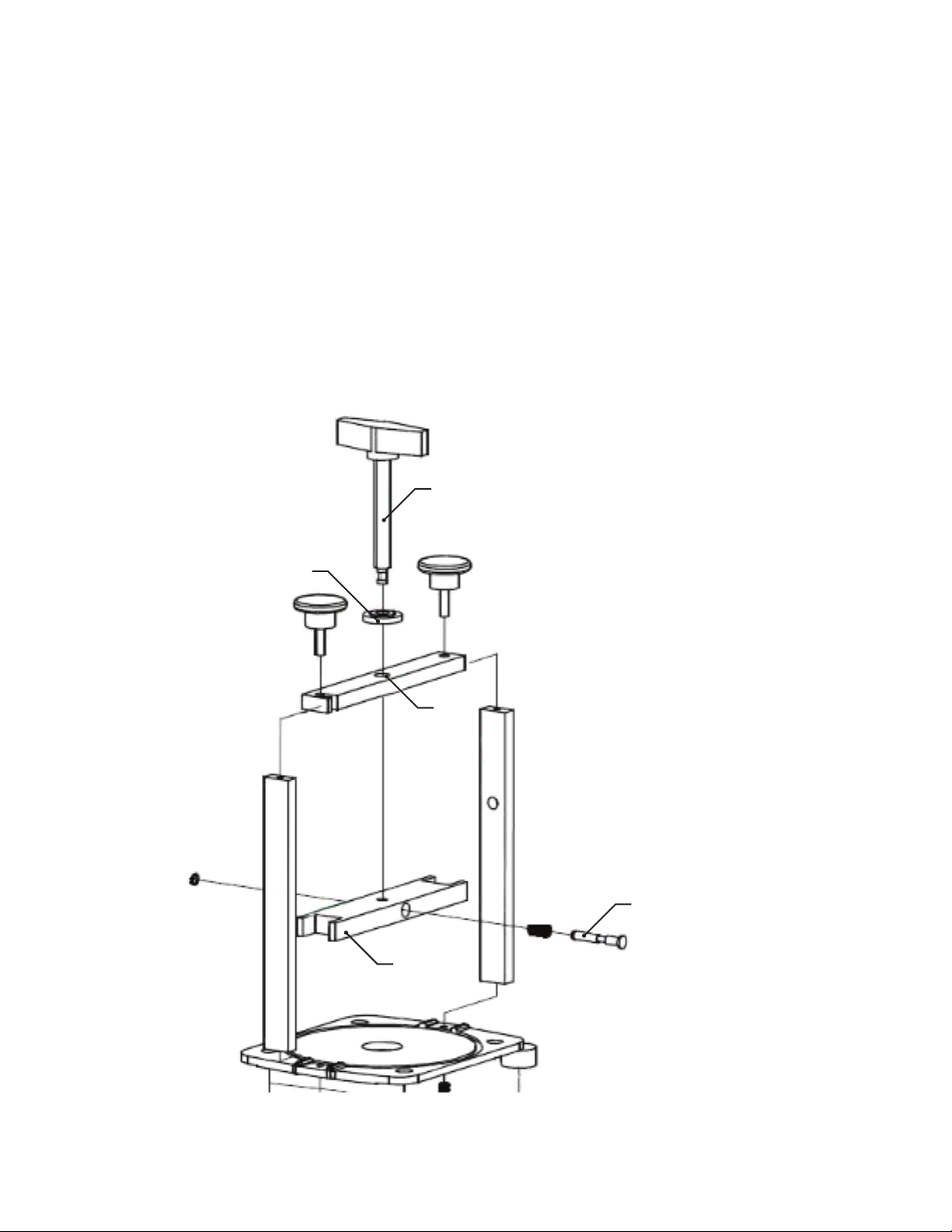
Fig. B:
1 2
3 4
F5 Paint Shaker
877-862-7049 www.F5PaintShaker.com
1. Locate the clamping screw (Part #1), insert it into the lock nut (Part #3) and then
into the hole in the bar (Part #4). Then insert the whole apparatus into the holding
bar (Part #7) while pushing in the locking pin (Part #8). (Fig. C)
2. Place your paint can into the machine and turn the clamping screw until the can
is securely fastened by the holding bar, leaving the lock nut free.
3. When you have secured the paint can, turn the lock nut down until it tightens to
the bar. Try giving both the nut and the clamping screw an extra ¹⁄4 turn at the
same time to ensure that it is tight. (Fig. D)
4. Rotate the timer switch (Part #30) to start the motor. Set the timer for two minutes
longer than intended mix time. User trial and error with varying times to find your
optimal mixing time.
Operating Instructions
Fig. C:
Clamping
Screw
Lock Nut
Hole
in Bar
Holding
Bar
Locking
Pin

F5 Paint Shaker
877-862-7049 www.F5PaintShaker.com
Fig. D:
NOTE: Place full rectangular gallons of primer to the left side of the platform rather than
the center.
1. Set aside the holding bar and clamping screw.
2. After loosening the knobs (Part #2), slide the right side of the top bar toward the front
of the machine using the slot in the right end of the the top bar to guide you. (Fig. E)
3. Keeping the top bar between the handle and the spout, slide the can onto the platform
of the machine.
4. When the can is centered evenly on the platform, tighten the knobs until the can is
securely clamped.
Instructions for Rectangular Cans:
Tighten Lock Nut

F5 Paint Shaker
877-862-7049 www.F5PaintShaker.com
Fig. E:
Diagram for Pint Cans (Fig. F) and Aerosol Cans (Fig. G):
Fig. F: Fig. G:
Slot
In Bar

F5 Paint Shaker
877-862-7049 www.F5PaintShaker.com
NOTES: Ther are two kinds of springs, lower (Part #21 and #24) and upper (Part #15)
and each type is sold in factory-matched sets of four. When one spring in the set becomes
damaged, the other three springs wear out faster as well, so you should replace all four.
Scratching or other damage to the spring wire during installation will cause the spring to
wear out faster.
The springs work in diametrically opposing pairs. Thus,each pair of springs should be
adjusted at the same time and in an equal amount.
How to Install the Springs
Lower Springs
1. Installation:
a. Find the first pair of springs, the two with the wide coil spacing, and use
two cap screws to attach them to the right front and the left back of the
frame.
b. Find the second pair of springs, the two with narrower coil spacing, and
attach them to the left front and right back as you previously did.
2. Adjustment: Only the upper springs will need adjustment, not the lower ones.
Replacement of lower springs may require adjustment of upper springs; Please
read “How to Check the Spring Adjustment” for instructions on this.
Upper Springs
1. Installation:
a. You will find that a ³⁄16” hex key fits through the threaded spring mount
hole into the cap screw that is assembled inside the spring. The screw
will fit through the mid-plate and threads into the lower spring’s top
mount.
b. Locate the two shortest springs and install them on the left front and right
back.
c. Located the two longest springs and install them on the right front and left
back.
d. Use four flat head cap screws to fix the can platform to the springs and
ensure that the screws are secure.
2. Adjustment: The springs are threaded onto the top spring mounts to provide for
optimal adjustment for shaking. If your springs have already been factory adjusted
and they are too stiff to shake, you will need to readjust the springs (back them off)
before operating the machine.
F5 Paint Shaker
877-862-7049 www.F5PaintShaker.com
Before proceeding to back off springs, ensure that you have fully installed the springs and
platform.
1. Carefully use a pair of pliers to grasp the top of the spring until the jaw catches onto the
end of the spring coil, making sure you do not gouge the spring wire. This will slightly
open the spring so that you can back it off the mount.
2. Back each spring off about ¹⁄4 turn and loosen the four flat head cap screws on the
platform. The springs will then snap back.
3. Retighten the four screws. Continue this until the end of each spring is ¹⁄4” away from
the platform. DO NOT BACK THE SPRINGS COMPLETELY OFF THE MOUNTS.
How to Back Off the Springs
1. To check if the springs need adjustment, place a full can of paint onto the platform,
secure it, and turn on the paint shaker. If you hear any clattering, there are loose
springs that need adjustment. If not, proceed to the next step (”How to Check the
Spring Adjustment”).
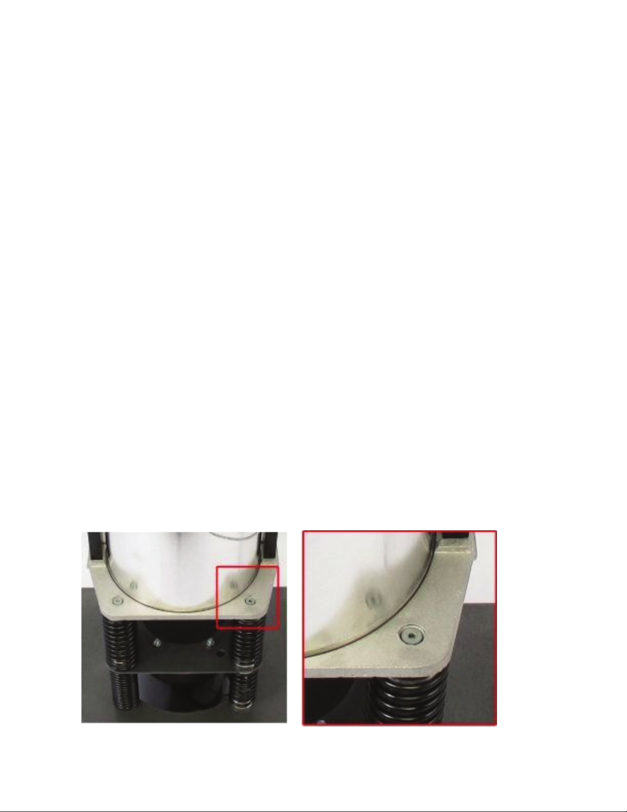
2. To determine which springs need adjustment, observe how the shaker’s mid-plate
moves while it’s on. If the right side moves more, tighten the right front and left back
springs (Fig. H). If the left side moves more, tighten the left front and the right rear
springs. If both sides move, tighten all four springs.
3. Turn off the machine before you tighten the springs. Take hold of the loose spring
and tighten it ¹⁄4 turn into the end mount. Then tighten that spring’s diametrically
opposite spring the same amount. Loosen the flat head cap screws on the springs
you have tightened, let the spring snap back, and then retighten the screws.
4. Turn on the machine again and once again observe if either side moves more than
the other. If so, repeat the procedure (always going ¹⁄4 turn at a time) until the
machine operates evenly on both sides.
How to Adjust the Springs
Fig. H:

F5 Paint Shaker
877-862-7049 www.F5PaintShaker.com
1. Start the machine and listen for clattering. If there is a clattering noise, go back to the
“How to Adjust the Springs” section. If there is no noise, proceed with the following
directions.
2. First, adjust all springs as necessary until the mid-plate moves in a uniform matter while
the machine is on. To do this, check for a few things. If one side moves more than the
other, the front spring on the side and its opposite spring needs to be backed off and the
spring set that moves more needs to be tightened. Refer to previous sections, “How to
Back Off the Springs” and “How to Adjust the Springs” to do this. You may proceed to
the next step when the mid-plate moves uniformly.
3. Turn on the machine and pay attention to the platform’s side to side movement. If the
machine moves more than ⁷⁄8” on both sides, tighten all springs ¹/8turn. If it moves less
than
³/4” on both sides, back off all springs ¹/8turn. You will know that the shaker is
properly adjusted if there is no clattering, the mid-plate moves uniformly, and the
mid-plate moves ³/4”.
How to Check the Spring Adjustment
NOTE: If you do not adhere to maintenance guidelines your warranty will be voided.
1. Clean paint splatters or spills off of the machine before they dry.
2. Regularly check the fasteners to make sure they are secure.
3. Check cords for damage; replace damaged cords before operating the machine
again.
Maintenance
Table of contents
Popular Paint Sprayer manuals by other brands


Bonide
Bonide 051 Operation and service instructions

zogics
zogics Z-DAS instruction manual

KISANKRAFT
KISANKRAFT KK-KBS-165 Operation manual

Matrix
Matrix SG 650 Translation of the original instructions

Anest Iwata
Anest Iwata SGA-3 Installation, use & maintenance instruction manual

paasche
paasche VV Instructions and parts list


