manuals.online logo
Brands
  1. Home
  2. •
  3. Brands
  4. •
  5. FA
  6. •
  7. Bathroom Fixture
  8. •
  9. FA Arc Enclosure User manual

FA Arc Enclosure User manual

FA/ ay 10
Arc Enclosure
Instruction anual
1. Check you have the correct enclosure and tray. Please look at the labels on the side of the product packaging.
2. Check all the product components are in the box and the fixing kits are complete. Please check this with the component
check list overleaf.
3. Unpack your product and handle it with care.
4. Please check the product for defects or damage. Once the installation has commenced we cannot accept responsibility for
any defects or damage to the products.
5. Please take the time to read these instructions prior to installing your product.
6. Before you commence any drilling check there are no hidden electrical cables and/or water pipes in the walls.
7. No attempt should be made to re-work the toughened safety glass.
8. The installation should be performed by two persons.
9. It is strongly recommended the walls the product is going to be installed on are vertical. However the wall profiles have
25mm of adjustment to help compensate for some deviation.
10. It is strongly recommended the product is fitted on tiled surface or similar waterproof surface.
11. It is strongly recommended the walls are tiled and grouted after the installation of the tray and before the installation of the
product. This will provide maximum adjustment and help when sealing the product.
12. If the walls and/or the tray are not level you will not achieve maximum adjustment of the product.
13. Pictures used are for illustration purposes only, product designs may alter slightly as a result of continuing product
development.
14. We do not stipulate where the European Standard Kite ark should be positioned on the glass panels when being factory
assembled.
I PORTANT INFOR ATION
• Roman’s toughened glass is completely safe for use in our shower enclosures and bath screens; providing our products are
installed according to our guidelines.
• It is important to note, that the glass must not be mounted or ‘pinched’ in such a way that would cause a stress point to
develop in the glass. In addition, it must not be subjected to any sharp impact or severe temperature fluctuation which may
also cause a stress point to develop in the glass.
• Roman’s toughened glass is physically and thermally significantly stronger than standard glass. During our toughening
process the stresses contained within any glass are balanced so if in the unlikely situation any of the above occurs and the
glass breaks, the glass will shatter safely into small thumbnail sized blunt fragments.
I PORTANT PRE-INSTALLATION CHECKS
Important: If you are fitting this product with integrated water delivery, the valve must be installed before
tiling the showering area and before the installation of this product.
FA
Consumer Guarantee - Please make sure the purchaser/end user completes and returns the Guarantee card
which is enclosed with this product. Failure to validate the Guarantee will mean only the 1 Year Statutory Guarantee will apply.
FA - Freedom Arc Dec 2009:CQB 4/5/10 12:05 Page 1
I PORTANT PRE-INSTALLATION CHECKS
1. Check the tray is level, on all sides (The bubble should be in the centre of the two lines on the spirit level).
2. Stand in the tray and check there is no adverse movement.
3. The walls should be tiled and grouted prior to installing the enclosure.
4. The tiles and the tray should be sealed, using bathroom sealant.
• Spray the seal and joints with the shower head and check for leaks.
• Check the plumbing for leaks.
• Do not grout the tiles when the enclosure has been fitted as the grout may discolour the
aluminum profiles.
• ake sure the tray is installed as per the manufacturers instructions.
• When all of the above criteria is complete please proceed to the next step in these instructions.
Step 1 - Checking the tray
Component Check List: Supplied
Description Quantity
Front Panel 1
Hinge Panel 1
Door 1
Wall Profiles 2
Wall Profile Trims 2
Handle Assemblies 1
Hinge Assemblies 2
Brace Bar Assembly 2
Door Bottom Seal 1
Fixing Kit - Component Check list.
40 mm Screws 8
Wall Plugs 8
16mm Pan Head Screws 6
Branding Badge 1
Profile Cover Caps 4
4mm Allen Key 1
3mm Allen Key 1
3mm Drill Bit 1
Plastic Tray Pin 2
Equipment Check List: Not Supplied
Description
ains or Battery drill
6mm asonry Drill Bit
Bathroom sealant gun
Bathroom sealant tube
Pozi Screw Driver
Spirit level
Tape measure
Pencil
Additional fixings if going into plaster board
10Nm Torque Wrench
FA - Freedom Arc Dec 2009:CQB 4/5/10 12:05 Page 2
1. Position the wall profiles using the guides on the tray, the lip of the profiles face towards the inside of the
enclosure (look at point 2 above).
• The wall profiles must be vertically level. Check using a spirit level. (The bubble should be in the centre of
the two lines on the spirit level).
2. ark the locations for the drill holes using a pencil.
• Use the supplied wall plugs if fitting the wall profiles into brick or block work, iF fitting into plasterboard,
the appropriate fixings will need to be used.
3. Drill the holes using 6mm masonry bit (not supplied). Then push the wall plugs in beyond the depth of the tile.
4. Apply sealant the width of the wall profiles, where they meet the tiles and the tray. (Important: failure to carry out
this procedure can cause serious water damage and is not covered by the guarantee).
5. Fix the Wall Profiles using the 40 mm screws (supplied).
6. Apply Sealant to the inside of the wall profiles, where they meet the tray. (Important: failure to carry out this
procedure can cause serious water damage and is not covered by the guarantee).
• (If you are fitting the enclosure straight to floor see the guidance page at the back of these instructions)
WALL PROFILE LIP
Step 2 - Fixing the Wall Profiles
FA - Freedom Arc Dec 2009:CQB 4/5/10 12:05 Page 3
Step 3 - Fit the hinge panel.
1. Select a panel and remove the black transit caps from the ends.
2. Screw one of the location pins into the bottom of the aluminum profile.
• ake sure that the locating pin projects enough so that it will locate into the tray.
3. Position the panel over the wall profile and place the location pin into the hole in the tray. ake sure the
glass is sitting parallel to the side of the tray and sitting horizontally along the edge of the tray.
4. Using a spirit level keep the panel vertical and drill through the pre-drilled holes of the wall profile using the
3mm drill bit (supplied).
5. Fix the panel to the wall profile using the 16mm pan head screws (supplied).
• The panel must be completely vertical (the bubble should be in the centre of the 2 lines on the spirit
level).
6. Fit the remaining panel by following steps1 to 5 as previously done.
• (You may need help to perform the installation steps, particularly to lift and hold the glass panel
in location).
(Please ensure the transport bands are removed with care from the glass panels in this and the
following steps. ake sure the vertical seals on the glass panels are carefully re-positioned).
FA - Freedom Arc Dec 2009:CQB 4/5/10 12:05 Page 4
1. Assemble the straight section of the brace bar onto the Low Level brace assembly and fasten together with the
countersunk screw: then slide the wall cup assembly onto the other end of the brace bar.
2. Position the full bracing assembly onto the panel but do not fix at this stage, slightly loosen the allen screw in
the low level bracing assembly so that it can be turned to achieve the correct angle
• No metal should touch the glass, the spacers must be used.
3. Slide the whole assembly up to the tiled wall to determine the position of the wall cup. ark around the cup
using a pencil.
4. Unscrew the brass insert from the end of the wall cup and position it in the centre of the pencil mark that you
have just done. ark through the slot for the position of the screw hole that is to be drilled.
5. Drill the location hole for the wall cup using a 6mm masonry drill (not supplied) and insert the wall plug.
6. Fix the brass insert to the wall using the 40mm screws (supplied) and then screw the wall cup onto the brass
insert so that it is tight up to the tiled walls.
7. Assemble the bracing bar back onto the panel and into the wall cup
• No metal should touch the glass, the spacers must be used.
8. When you are satisfied that the brace bar has been positioned correctly, tighten all the screws on the wall cup
and on the low level brace assembly with an allen key.
9. To fit the bracing on the other panel simply follow steps 1 to 8.
• There is 18mm of adjustment in the brace bar to allow for correct alignment.
• Both panels must be vertically level, make sure the bracing is adjusted to achieve this.
Step 4 - Assembling the Brace Bars (If you are fitting with intergrated water
delivery, please refer to your valve instructions for this step)
➂➃
➄
➀
➆
➅
FA - Freedom Arc Dec 2009:CQB 4/5/10 12:05 Page 5
Step 5 - Fitting the door and seals
1. Assemble the handle onto the door. (There should be no metal toughing the glass. The spacers must be
used)
2. Assemble the hinges onto the hinged panel. (There should be no metal toughing the glass. The spacers
must be used). Lightly tighten the hinge bolts using an Allen Key.
• ake sure the hinges are assembled the correct way up. The hinge pin in the centre should only be able
to be removed fromo the top of the hinge. This is important - take time to check this.
3. Assemble the bottom seal onto the door and cut to length if necessary. The bottom seal must be positioned
flush up against the vertical magnet seal at one end of the door, and cut level to the end of the glass at the
other end of the door. See Fig: 5 (The seal must be cut square and accurately using a retractable knife or
alternative blade)
4. Lift the door towards the hinge panel and into location on the hinges. ake sure the panel seal flap sits
behind the door glass. Assemble the hinges onto the door. (There should be no metal touching the glass.
The spacers must be used). Lightly tighten the hinge bolts using an Allen Key.
5. ake sure the door deflector seal is locating its full length horizontally along the tray.
6. Align the hinges so they are at 90 degrees to the glass, check using a spirit level, when you are satisfied
tighten the hinge bolts to 10Nm using a torque wrench.
• (You will need help to perform the installation steps, particularly to lift and hold the front panel into
location).
7. Close the door onto the front panel, with the door closed align the magnets so that the door and panel
magnets locate evenly the full length.
• You may need to move the magnets towards each other to achieve a seal.
• You may need to adjust the bracing on the panels so that the dor and panel meet.
Door seal flush
with magnet seal
Door seal cut level to
the end of the glass
➂
➂ ➄
➀ ➆ ➃
FA - Freedom Arc Dec 2009:CQB 4/5/10 12:05 Page 6
1. Clip on the wall profile cover trims. (They are designed to be a tight fit so take care).
2. Place all the cover caps on the profiles. (R and L on the inside of the caps indicate the handing of the caps looking
from the outside of the enclosure).
3. Place the Hinge Cover caps over the screw heads.
4. Stick on the Branding Badge.
5. Seal vertically the full length of the wall profiles/wall profile trims, where they meet the tiles on the inside of the
enclosure, using bathroom sealant. Also seal vertically the full length of the wall profiles where they meet the
tiles on the outside of the enclosure, using bathroom sealant.
6. Seal horizontally the aluminum profiles and the glass panels on the outside of the enclosure at the bottom where
they meet the tiles and the tray using bathroom sealant.
• (Please leave the sealant 24hrs to cure before use).
• I PORTANT: Failure to follow the procedure in steps 5 and 6 can result in serious water damage and is
not covered by the guarantee.
• (If you are fitting the enclosure with integrated water delivery please refer to your valve instructions to
complete the installations).
Step 6 - Fix the Cover Caps and Seal the enclosure.
FA - Freedom Arc Dec 2009:CQB 4/5/10 12:05 Page 7
ITE NO. Part Number Colour QTY Description
1 ROGWPS Silver 2 Wall Profile
2 RI 0211 Chrome 1 Screw Cover Cap (L-H)
3 ROG02S Silver 2 Screw Cover Trim
4 RI 0207 Chrome 1 Vertical Cover Cap (L-H-)
5 R C0096 Chrome 2 45 degree Wall Cup Assembly
6 R C0178 Chrome 2 25mm Brace Bar
7 R C0097 Chrome 2 Low Level Bracing Assembly
8 RG0092 Clear 2 Angled agnet
9 OF04 Clear 1 6mm Curved Door Glass
10 R C0076 Silver 2 Freedom Hinge
11 RG0130 Clear 1 Vertical Door Seal (C1064)
12 RI 0206 Chrome 1 Vertical Cover Cap (R-H)
13 RI 0210 Chrome 1 Screw Cover Cap (R-H)
14 RSCR48 Grey 2 Plastic Tray Pin
15 N/A N/A 1 Large Panel Assembly
16 R C0069 Silver 1 New Orbital Handle 240mm Centres
17 RGO149 Clear 1 Bottom Seal
18 N/A N/A 1 Small Panel Assembly
Spare Parts: If you require any spare parts, please look at the parts list below then call
customer services on 01325 328034
NB: If ordering item 18 please state Left or Right Hand.
FA - Freedom Arc Dec 2009:CQB 4/5/10 12:05 Page 8
Straight to floor guidance
Should you experience any problems during installation please refer to the
Trouble Shooting Guide or contact Customer Relations on:
+44 (0) 1325 328033/328034
To enable customer relations to provide you with an excellent level of service it is important that you quote your
Product Code and Reference Number - these numbers can be found on the guarantee card.
Locating the wall profiles and using the panel location pins (steps 2, 3 and 5).
The measurements above need to be used to locate the wall profiles (step 2).
The location pin measurements above need to be used to located the glass panels (step 3 and 5).
1. In order to use the location pins follow the measurements above to determine the positions.
2. Drill a 9 mm diameter hole with a recommended depth of 10mm, using suitable a drill bit.
3. Screw the location pins into the bottom of the aluminum profiles on the glass panels.
4. Continue with the installation by following the instructions.
• Caution: Before you commence any drilling check there are no hidden electrical cables and/or water
pipes under the floor and make sure you have enough depth in the floor to locate the pin. Do not
puncture the wet room membrane during the drilling. If you are unsure about the installation seek
professional advice.
The Location pins can be cut down from the non threaded end if required.
FA - Freedom Arc Dec 2009:CQB 4/5/10 12:05 Page 9
TROUBLE SHOOTING GUIDE.
Problem Solution
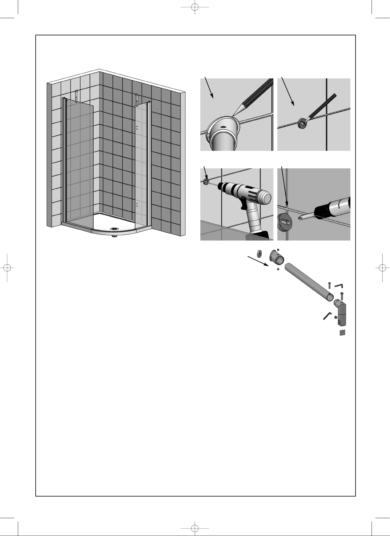
LEAKING 1. Check the enclosure has been sealed correctly as per the instructions:
2. The tray and tiles prior to the enclosure installation (Step 1).
3. The width of the wall profiles at the bottom where they meet the wall and the tray (Step 2).
4. Inside the wall profiles where they meet the tray (Step 2).
5. Vertically on the inside of the enclosure the full length of the wall profiles/wall profile trims where they
meet the tiles (Step 6).
6. Vertically on the outside of the enclosure the full length of the wall profiles where they meet the tiles
(Step 6).
7 Horizontally along the glass and aluminium on the outside only (Step 6).
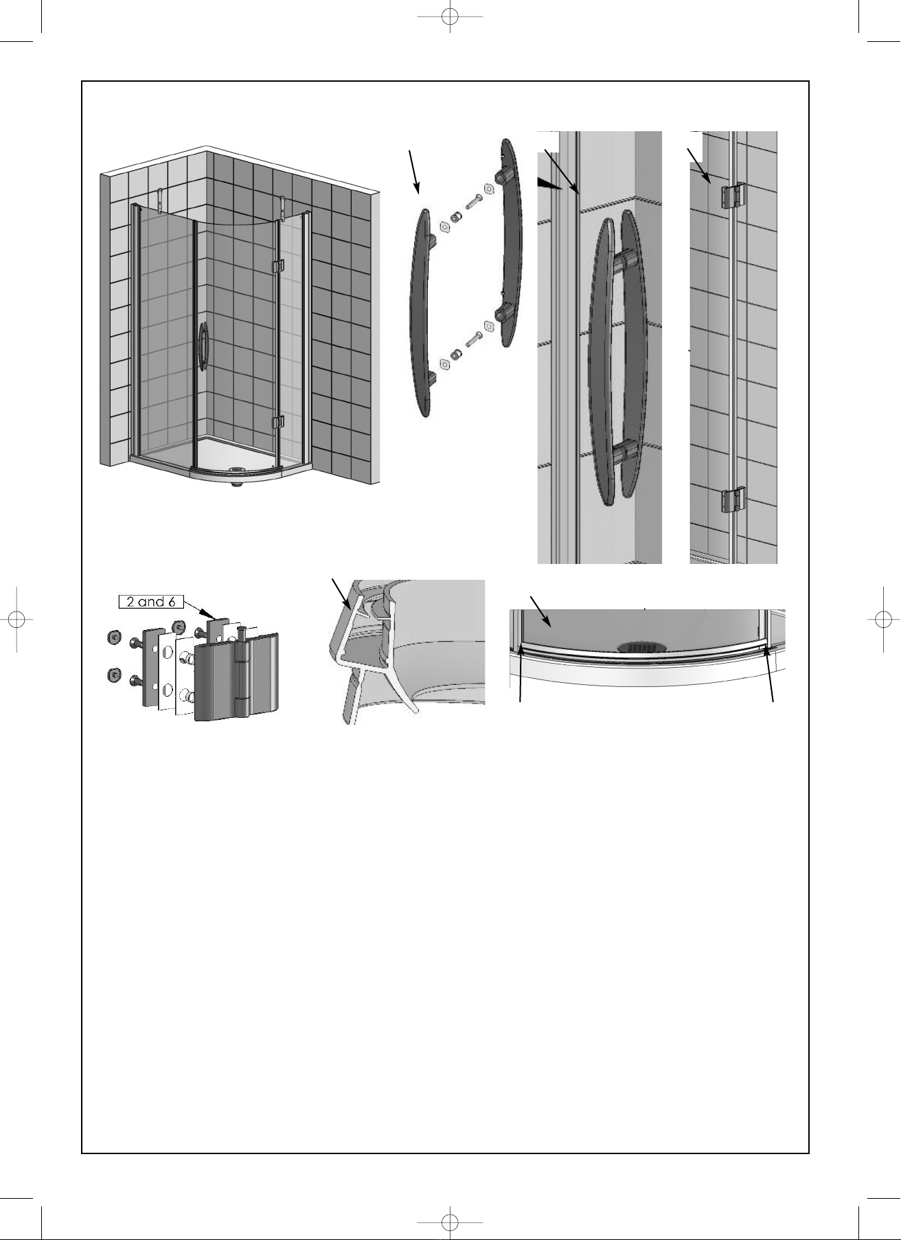
8. Check the horizontal door seal is fully locating along the sealing strip on the tray (Step 5)
9. Check the bottom door seal has been cut accurately to locate onto the vertical seals at the bottom of
the door and panel (step 5).
10.Check the vertical door and panel magnet seal are locating along the full length (Step 5).
ENCLOSURE 1. Check the wall profiles have been installed as per the instructions:
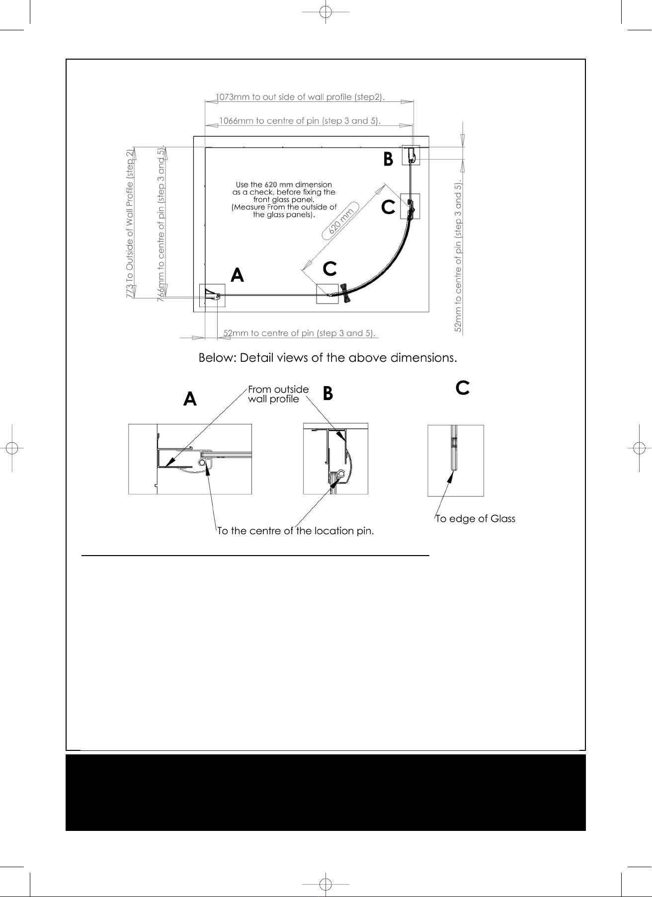
ALIGN ENT 2. ake sure they are vertically level (Step 2).
ON TRAY 3. Check the tray installation (Step 1).
4. Check the brace bar has been installed as per the instructions:
5. Check the brace bar is level (Step 4).
6. Check the panels are vertically level (Step 4).
DOOR NOT 1. Check the tray installation:
OPERATING 2. Check the tray is level (Step 1).
S OOTHLY 3. Check the wall profiles have been fitted as per the instructions:
4. ake sure they are vertically level (Step 2).
5. Check the panels have been fitted as per the instructions:
6. ake sure they are vertically and horizontally level (Step 3).
7. Check the hinges have been fitted as per the instructions:
8. Check the hinges are level (Step 5).
Some important information to help you aintain your product.
The following information is all you need to keep your product looking new.
Clean your product using a mild detergent diluted in water and then polished off using a soft cloth.
If you live in a hard water area, periodically clean your product using a 50/50 solution of white vinegar and water. The solution
should be left on the enclosure for approximately 5 minutes then rinsed off using warm water. This method of cleaning should
remove lime scale residue.
Simple maintenance.
Our products are generally maintenance free, however it may be necessary to lubricate wheel assemblies and other moving parts
from time to time.
It is strongly recommended that a quality silicone spray is used.
A list of Don'ts:
1 - Don't use acidic based products which are unsuitable for cleaning enamel surfaces.
2 - Don't use Abrasive cleaners or cleaners containing bleach or solvents, these products will adversely affect the finish of the
aluminium profiles.
3 - Don't use scouring pads, powder or any sharp instruments when cleaning the enclosure.
FA - Freedom Arc Dec 2009:CQB 4/5/10 12:05 Page 10

Popular Bathroom Fixture manuals by other brands

HOESCH ADANA installation instructions

HOESCH

HOESCH ADANA installation instructions

KRION NER PRE-INSTALLATION AND INSTALLATION MANUAL

KRION

KRION NER PRE-INSTALLATION AND INSTALLATION MANUAL

INDA A0415A Mounting instructions

INDA

INDA A0415A Mounting instructions

AQUANCE BETO installation guide

AQUANCE

AQUANCE BETO installation guide

KEUCO 800021DDEG0XX00 Instructions for use

KEUCO

KEUCO 800021DDEG0XX00 Instructions for use

Roltechnik LLR 900 installation manual

Roltechnik

Roltechnik LLR 900 installation manual

RIHO GRID GB400 installation manual

RIHO

RIHO GRID GB400 installation manual

VIGO NOMA V601009 manual

VIGO

VIGO NOMA V601009 manual

newform X-STEEL 316 69623X instructions

newform

newform X-STEEL 316 69623X instructions

Decor Star PL-035-SS manual

Decor Star

Decor Star PL-035-SS manual

Symmons SCOT SLS-7000 Series Operation & maintenance manual

Symmons

Symmons SCOT SLS-7000 Series Operation & maintenance manual

aidservice 7700 USER GUIDE & PRODUCT INFORMATION

aidservice

aidservice 7700 USER GUIDE & PRODUCT INFORMATION

Orbital Systems Panel Quick installation guide

Orbital Systems

Orbital Systems Panel Quick installation guide

Sanela SLZM 18 49180 Mounting instructions

Sanela

Sanela SLZM 18 49180 Mounting instructions

SCHÜTTE 60044 installation instructions

SCHÜTTE

SCHÜTTE 60044 installation instructions

Fantini Rubinetti ACQUA ZONE C001AU instructions

Fantini Rubinetti

Fantini Rubinetti ACQUA ZONE C001AU instructions

Costway OP3553 user manual

Costway

Costway OP3553 user manual

Sanipex AQUAECO AQM-CND-301-XX installation guide

Sanipex

Sanipex AQUAECO AQM-CND-301-XX installation guide

manuals.online logo
manuals.online logoBrands
  • About & Mission
  • Contact us
  • Privacy Policy
  • Terms and Conditions

Copyright 2025 Manuals.Online. All Rights Reserved.