FAAC TM2 E User manual
TM2 E

- Per evitare situazioni di pericolo o malfunzionamento, gli elementi elettrici di
comando collegati al motore devono essere dimensionati in base alle caratte-
ristiche elettriche del motore stesso.
- I dispositivi di disconnessione devono essere previsti nella rete di alimentazione
conformemente alle regole di installazione nazionali.
- I selettori per l’inversione del senso di rotazione del motore devono essere muniti
di interblocco meccanico.
- Per modificare il senso di rotazione, invertire i conduttori marrone e nero.
- Non collegare due o più selettori sullo stesso motore.
- In caso di utilizzo all’esterno, utilizzare un cavo di alimentazione a designazione
H05RN-F contenuto di carbonio min 2%.
- Non utilizzare cavi di collegamento fra il selettore e il motore più lunghi di 50
m. Nel caso sia necessario comandare il motore oltre questa distanza interporre
un relè di isolamento.
COLLEGAMENTI ELETTRICI
TM2 E 2 A4516_6J97_Rev.A
IT
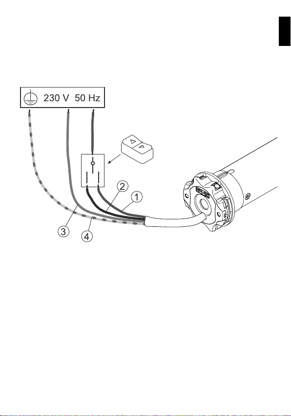
COLLEGAMENTI ELETTRICI
1- marrone
2- nero
3- blu
4- giallo-verde
TM2 E 3 A4516_6J97_Rev.A
IT
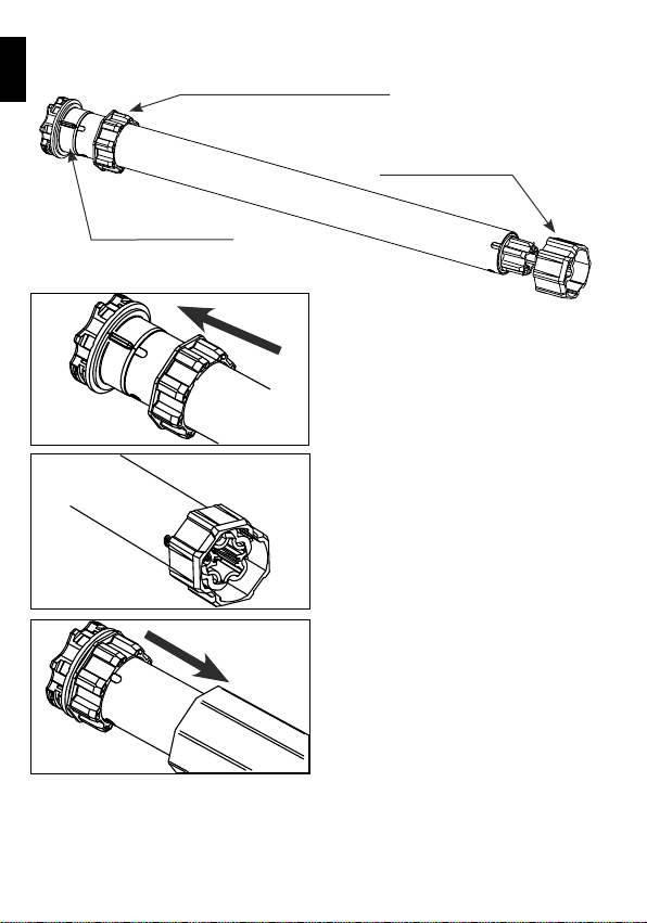
PREPARAZIONE DEL MOTORE
NB: Nel caso di tubi con profilo tondo la puleggia di traino deve essere fissata al
tubo, questa operazione è a carico dell’installatore. Per altri profili di tubo il fissaggio
è facoltativo anche se fortemente raccomandato.
ADATTATORE GHIERA
PULEGGIA DI TRAINO
GHIERA
1. Inserire l’adattatore sulla ghiera facen-
do combaciare la scanalatura con la tacca
di riferimento e spingere fino alla battuta.
2. Montare la puleggia di traino sul perno
del motore fino allo scatto della molla
di fermo.
3. Introdurre completamente il motore
nel tubo di avvolgimento.
TM2 E 4 A4516_6J97_Rev.A
IT
1
2
3
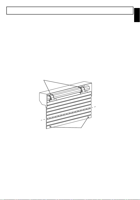
MODALITÀ AUTOMATICA
ISTRUZIONI D’USO
Il motore è di semplice installazione e utilizzo, non necessita di alcuna regolazione
in quanto riconosce automaticamente i finecorsa.
La tapparella deve essere equipaggiata con:
A - Cintini rigidi o molle antieffrazione,
B - Tappi di sicurezza fissi o rimovibili nelle guide.
Si raccomanda di controllare sempre la robustezza della tapparella.
A
B
N.B. Finchè entrambe le posizioni dei finecorsa non sono state memorizzate, all’inizio
di ogni movimentazione il motore esegue una breve rotazione, si ferma e poi riprende
normalmente.
Dopo alcune corse le posizioni di finecorsa vengono memorizzate automaticamente.
TM2 E 5 A4516_6J97_Rev.A
IT
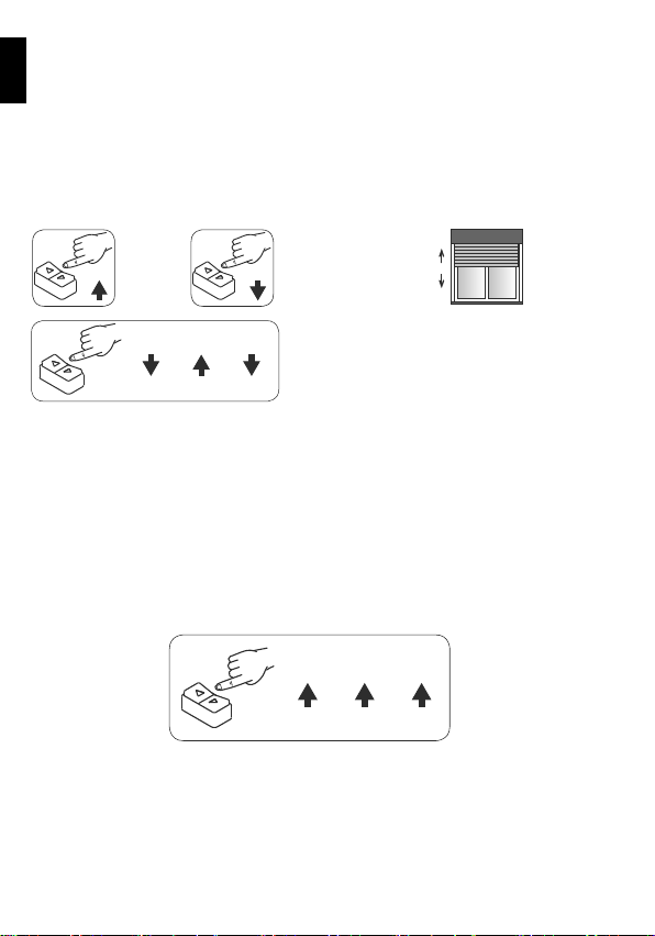
SPIEGAZIONE DELLE SEQUENZE DI COMANDO
UPUP UP
La maggior parte delle sequenze di comando è composta da tre o sei passi ben
distinti. I pulsanti devono essere premuti per meno di 0,5 secondi come indicato
nella sequenza, senza far passare più di 1 secondo tra un passo e l’altro. Se trascorre
più di 1 secondo il comando non viene accettato, e si dovrà ripetere la sequenza.
Esempio di sequenza di comando in 3 passi:
LEGENDA DEI SIMBOLI
UP DOWN
premere
il pulsante
di salita
premere i pulsanti come indicato
in rapida sequenza
premere
il pulsante
di discesa
DOWN DOWNUP
DISCESA (DOWN)
SALITA (UP)
MODALITÀ MANUALE
In questa modalità è facoltativa la presenza di dispositivi quali:
A - Cintini rigidi o molle antieffrazione,
B - Tappi di sicurezza fissi o rimovibili nelle guide
TM2 E 6 A4516_6J97_Rev.A
IT

MEMORIZZAZIONE DEI FINECORSA
MEMORIZZAZIONE DELLA POSIZIONE DI FINECORSA SUPERIORE
Se la tapparella è già completamente avvolta, si dovrà prima abbassare di circa 20 cm.
Con i pulsanti di salita della pulsantiera, portare la tapparella in posizione di aper-
tura desiderata. Per memorizzare la posizione di apertura, eseguire la sequenza di
comandi indicata (UP-UP-UP).
MEMORIZZAZIONE DELLA POSIZIONE DI FINECORSA INFERIORE
Con il pulsante di discesa della pulsantiera, portare la tapparella in posizione di
chiusura desiderata. Per memorizzare la posizione di chiusura, eseguire la sequenza
di comandi indicata (DOWN-DOWN-DOWN).
UP
DOWN DOWN DOWN
UP UPUP
DOWN
MODALITÀ MISTA
È sempre possibile eseguire memorizzazioni miste delle posizioni di finecorsa ad
esempio:
- Finecorsa di Apertura: automatico in battuta;
- Finecorsa di Chiusura: manuale con sequenza da pulsantiera.
TM2 E 7 A4516_6J97_Rev.A
IT

UP UPDOWN DOWN DOWN DOWN
UP UP UP UPDOWN DOWN
CANCELLAZIONE TOTALE DELLE POSIZIONI DI FINECORSA
CANCELLAZIONE DELLE SINGOLE POSIZIONI DI FINECORSA
Cancellazione dei finecorsa dalla posizione di finecorsa SUPERIORE
Cancellazione del finecorsa SUPERIORE
Posizionare la tapparella/
tenda in posizione di fine-
corsa superiore ed eseguire
la sequenza indicata:
Posizionare la tapparella/
tenda in posizione di fine-
corsa superiore ed eseguire
la sequenza indicata:
Posizionare la tapparella/
tenda in posizione di fine-
corsa inferiore ed eseguire
la sequenza indicata:
Posizionare la tapparella/
tenda in posizione di fine-
corsa inferiore ed eseguire
la sequenza indicata:
Cancellazione dei finecorsa dalla posizione di finecorsa INFERIORE
Cancellazione del finecorsa INFERIORE
Dopo la cancellazione di uno od entrambi i finecorsa il motore si muove con un
ritardo di 0,5 sec. finchè entrambe le posizioni non vengono nuovamente memo-
rizzate in modalità automatica o manuale.
UPDOWN DOWN DOWN DOWN DOWN
UP UP UP UP UPDOWN
TM2 E 8 A4516_6J97_Rev.A
IT

FINECORSA IN BATTUTA
(tapparella con tappi e/o cintini rigidi).
RILEVAZIONE OSTACOLI IN SALITA E
DISCESA
(in discesa solo per tapparelle con
cintini rigidi).
TM2 E Normalmente si ferma qualche mm
prima della battuta. Periodicamente,va
in battuta e non effettua il movimento
contrario di rilassamento.
Si arresta e non inverte il moto.
COMPORTAMENTO DEI MOTORI SU FINECORSA IN
BATTUTA E OSTACOLO
RIPRISTINO DELLA CONFIGURAZIONE ORIGINALE
Per ripristinare la configurazione originale del motore eseguire la procedura:
- collegare i fili del motore Marrone e Nero sotto lo stesso pulsante, es. SU;
- premere il pulsante SU per almeno 2 secondi;
- scollegare e ripristinare il collegamento elettrico dei pulsanti di comando.
1- marrone
2- nero
3- blu
4- giallo-verde
GIÙSU
TM2 E 9 A4516_6J97_Rev.A
IT

FAAC S.p.A. Soc. Unipersonale dichiara che il Motore TM2 E è conforme alle
pertinenti normative di armonizzazione dell’Unione: Direttiva 2014/30/EU,
Direttiva 2011/65/EU.
Il testo completo della dichiarazione di conformità EU è disponibile al seguente
indirizzo Internet: http://www.faac.biz/certificates
DICHIARAZIONE DI CONFORMITÀ EU
DICHIARAZIONE DI INCORPORAZIONE DI QUASI-MACCHINE
(2006/42/EC ALL.II P.1, LETT. B)
Fabbricante e persona atta a costituire la documentazione tecnica pertinente
Ragione Sociale: FAAC S.p.A. Soc. Unipersonale
Indirizzo: Via Calari, 10 - 40069 Zola Predosa BOLOGNA – ITALIA
con la presente dichiara che per la quasi macchina:
Descrizione: Motori tubolari per tende e tapparelle
Modello: TM2 E
Tutti i requisiti essenziali della Direttiva Macchine 2006/42/EU (comprese
tutte le modifiche applicabili) sono applicati e soddisfatti. La documentazione
tecnica pertinente è stata compilata in conformità dell’allegato VII B.
Inoltre sono state applicate le seguenti norme armonizzate:
EN 60335-2-97:2006+A2:2010+A11:2008+A12:2015.
Si impegna inoltre a trasmettere per posta o per via elettronica informazioni
pertinenti sulla quasi-macchina in risposta ad una richiesta adeguatamente
motivata delle autorità nazionali.
Infine dichiara che la quasi macchina sopra individuata non deve essere mes-
sa in servizio finché la macchina finale in cui deve essere incorporata non è
stata dichiarata conforme alle disposizioni della suddetta Direttiva Macchine
2006/42/EC.
Bologna, 25-03-2019 CEO A. Marcellan
TM2 E 10 A4516_6J97_Rev.A
IT
Table of contents
Languages:
Other FAAC Window Blind manuals

Popular Window Blind manuals by other brands


Current
Current E-WAND Installation manual and user's guide

weinor
weinor VertiTex ZipR Maintenance Instructions and Directions for use for the end user

Roto
Roto ZAR M R4/R7 Mounting instructions

SOMFY
SOMFY Movelite WT Series instructions

Acmeda
Acmeda RF400 Series instructions

Motura
Motura Pli_353/3 manual