LanternLITE KuroLok RL User manual

FITTING INSTRUCTIONS
1

2
Drive-end headbox
Side channels x2
Side channel zip
inserts x2
Roller blind (already
inside the headbox)
You will need to use fixings suitable for the substrate you are
fixing to, these are not provided
There will also be an orange bag containing any small critical
items. This is likely to contain the controls for the blind if these
were ordered
Please unpack the delivery and check you have:
PLEASE NOTE:
THIS IS A 2+ PERSON
INSTALLATION
Spring tension-end
headbox

3
NOTE
IMPORTANT
The installation instructions in this guide should be followed otherwise the
warranty will be void.
It is the duty of the installer to pass on user and maintenance instructions to
the end user. The installer must also demonstrate the blind is fully working in
their handover to the end user.
Motorised blinds must be connected to an RCD protected circuit.
It is the installers responsibility to ensure that suitable fixings are used to
secure the blind in place
It is the installers responsibility to ensure safety is always maintained. A full
risk assessment must be carried out and documented prior to installation.
Use these instructions to fit the blind. The product has evolved slightly since
the fitting video was produced.
BEFORE INSTALLATION
If you are unsure of any element of the install, please contact us before
proceeding
All components should be checked for damage. Damaged components should
be reported to us prior to the installation beginning.

4
CTS UNIT WARNING
Please read before proceeding
This blind contains constant tension spring (CTS) units.
Take great care when pulling the cord out of the CTS! These are powerful units and can
cause damage or injury if misused!
Under NO circumstances must the cord be released to wind back into the CTS
unchecked. If this happens it WILL result in damage to the CTS and MAY ALSO result in
injury or damage to persons or property.
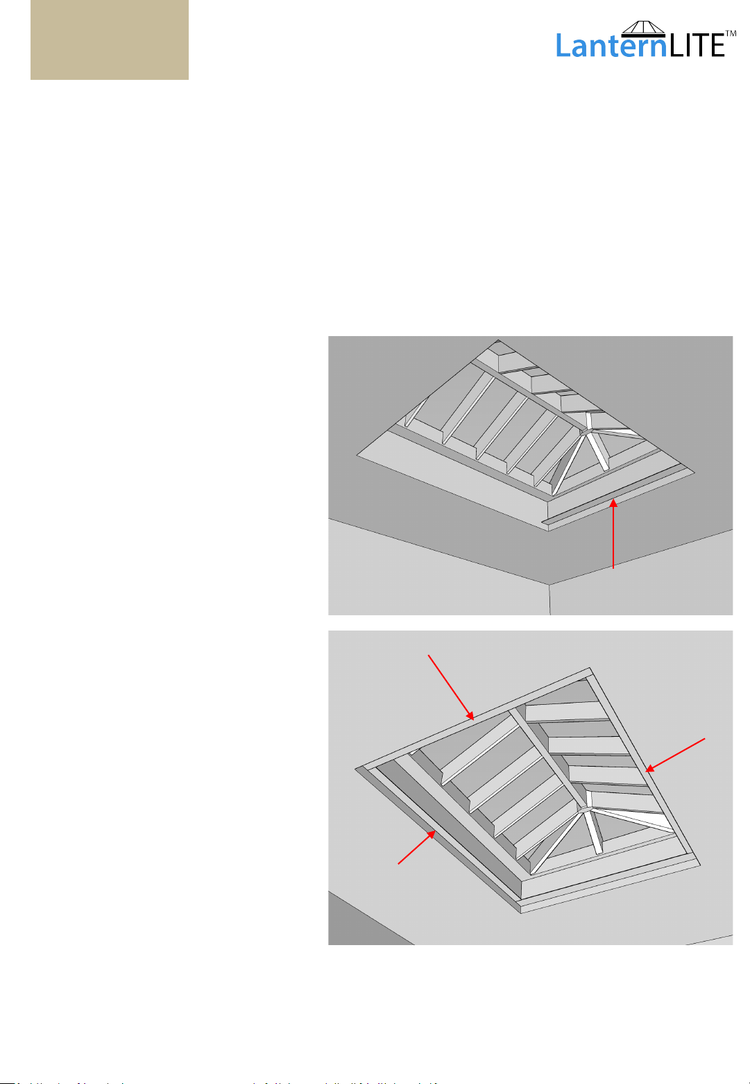
For your convenience and safety every CTS is provided with a locking point, which is
marked with an orange arrow. Pull the cord to rotate the spool inside the CTS until you
see the hole in the spool line up with the locking point. Insert a pin* through the locking
point into the spool to lock the CTS.
*for a locking pin you may use any metal shaft of 3-4mm diameter, e.g. small
screwdriver or screw. Ensure this does not fall inside the CTS unit.
To remove the locking pin, pull the cord tight to take the tension off the pin, lift the pin
out and allow any slack cord to SLOWLY feed back into the CTS.
In some cases your blind will be delivered with the CTS already locked with a screw
inserted into the locking point. DO NOT USE A SCREWDRIVER TO REMOVE THIS SCREW,
but remove it following the instructions above.
Locking Point
Tension Cord
NOTE

5
Fitting Options Note
There are many ways you can fit a LanternLITE™ blind. The recommended
installation method is STANDARD ORIENTATION on top of L-Profile Shelf Angle as
covered in this manual
Some of the other fixing options are shown below but should only be considered by
installers that have received training for these fitting methods.
Reverse orientation, face fix
outside the reveal
Reverse orientation, inside the
reveal
Standard orientation, side fixed
inside the reveal
Standard orientation on
aluminium batten/angle, side
fixed inside the reveal
AS SHOWN IN THIS MANUAL
NOTE

We recommend using our aluminum angle to assist installation.
If you choose not to use our aluminium angle, please be aware that the
installation will be more challenging. More time will need to be spent fine
tuning the framework to ensure the blind operates correctly.
STEP 1
6
Begin by fitting angle at the
end of the recess opening
where the roller blind and
motor will be located
This is the start of the shelf.
Offer the other 3 lengths of
angle into position and drill
fixing holes ready for these to
be fitted into place.
Do not fix these into position
yet.
NOTE
Angle/batten can be trimmed
to fit if necessary, using a
hacksaw or chop saw with a
metal cutting blade.

7
Remove the screw from each end of the
headbox containing the spring units. Keep
these screws (x2) in a safe place until the
end of the installation
STEP 2
Preparing your blind.
Remove the front cover from the tension
end by hinging up by approx. 8mm and
sliding back slightly to release it.
Leave the front cover on headbox
containing the blind.
Reverse this procedure to replace the
front cover at the end of the installation.

8
Slide the side channels onto the steel legs
of the headbox end cheeks to form a
rectangle on the floor.
STEP 3
Assembling your blind.

9
Pull out enough cord from both
CTS units to reach the roller
blind hembar + 100mm
Use a long screw or hex key to lock
the tension by inserting it into the
locking point indicated by the
sticker.
After you put this into the hole,
allow a bit of cord to go back into
the box until the tension locks
against the screw/drill bit.
Repeat for the other CTS units
Preparing the tension cords.
STEP 7
Distance to hembar + 100mm (approx.)
STEP 4

10
Hook the loop on the end of the cord over
the stand-off on the hembar endcap.
Do not let it fall off whilst the tension is
locked at the CTS Units
Attaching the tension cords.
STEP 5
Be careful not to let the loop drop
off whilst the cord is still slack.

11
Take up the slack cord and remove the
locking pin from the spring box.
Keeping the cord taut slowly let the
spring take up the slack. Tension will be
immediately applied to the cord.
Applying tension
STEP 6
Under NO circumstances must the cord be released to
wind back into the CTS unchecked. If this happens it WILL
result in damage to the CTS and MAY ALSO result in injury
or damage to persons or property.

12
Now offer the blind up to the window
sitting the motor end headbox on the
angle you have already fixed in place.
STEP 7
Aluminium Angle
Lift the blind into the reveal and fix the
remaining 3angles into place using the
holes you havepre-drilled
Your LanternLITE™ blind should now
be sitting ontop of the batten.

13
STEP 8
General Fixing Note
If the fixing type was not stated on the purchase order the side channels
will not be pre-drilled.
Face Fix –drill a 5mm hole all the way through the face of the channel on the
drill line, then enlarge the front hole to 8.5mm
Reveal Fix –drill a 5mm hole through the side of the channel
Cover caps to conceal face fix holes are available from your supplier.
It is the installers responsibility to ensure correct and suitable fixings
are used for the substrate being fixed to

14
STEP 9
Ensuring the blind is square is critical to the successful
operation of the blind.
Side fix through the channels and through the angle.
Work your way along the channels using a tape measure to ensure that the side
channels are the same distance apart at each fixing point.
IMPORTANT NOTE
Larger roof blinds may need the channels to be closer in the middle than at the
headbox ends. This can be achieved by slackening the middle fixing and adding
up to 10mm of packers at that point.
This maybe necessary if you find the blind sticks or jambs during travel.

15
STEP 10
Fitting the zip insert into the side channels.
Unroll the blind by
approximately 50mm.
Start to slide one end of
the black plastic insert up
the channel with the fins
facing outwards.
Engage the zip at the
bottom of the hembar,
with the opening at the
centre of the plastic
insert.
Once you have caught
the end of the zip in the
plastic insert, angle the
insert so it is nearly
parallel with the side
channel and start to slide
the insert up the zip on
the edge of the fabric
ensuring the zip stays
engaged with the insert.
Once the insert is level
with the top ofthe side
channel you can push it
back into the channel.
Spray silicone down
each ZIP insert.
Ensure that the fins
locate inside the returns
on channel for the full
drop of the blind.
INSTALLER’S TIP: You will find this Step easier if you first remove the tension
cords from the hembar. Use the instructions on pages 9-11 to safely remove
the tension cords, and reattach them after you have completed Step 10,
before moving on to Step 11. Please read the CTS warning on page 4.

16
STEP 10
Motor commissioning.
The motor must now be commissioned. Standard motor setup instructions
will beincluded with thedelivery. Alternatively instructions can also be found
at the bottom of the page on the linkbelow.
https://www.skylight-blinds-direct.co.uk/skylight-roof-lantern-blinds-
lanternlite.html
Mains powered motors must be connected toan RCD protected circuit.
Once the commissioning has been done, clip the front cover into place and
secure it with a screw at each end.
Your installation is now complete
Table of contents