17GB
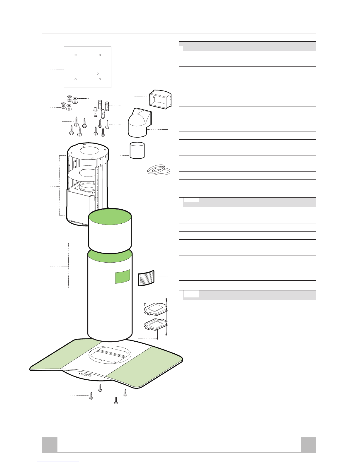
Upper frame
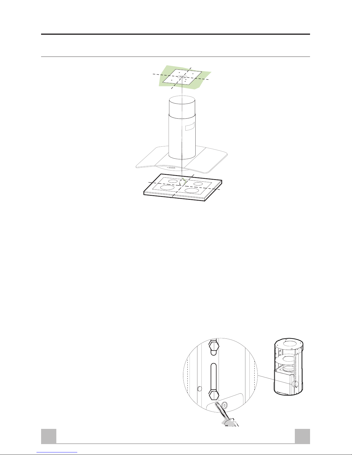
•Align the power supply cable feed hole
•Fix the upper frame to the ceiling or shelf using:
•For concrete ceilings, use the appropriate plugs for the screw size (not provided).
•For hollow brick ceilings of wall thickness of approximately 20 mm: use 4 plugs 11 and 4
screws 12h, provided.
•For wooden beam ceilings, use 4 wood screws (not provided).
•For wooden shelf, use 4 screws 12g with washers 22 and nuts 23, provided.
Lower frame
•Fix the lower frame using the 8 previously removed screws, adjusting the length according to the
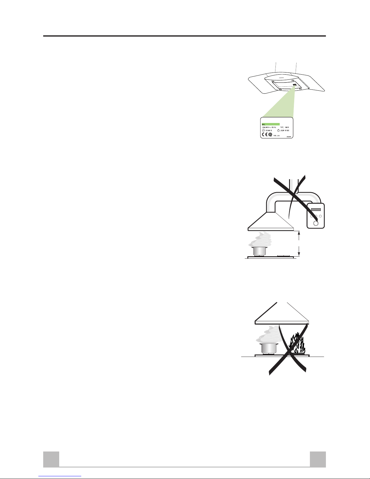
installation height (hood body lower fixing surface must be at least 720 mm from the hob).
•For the recirculation version, turn the frame in the direction chosen for the recirculated air outlet.
•The frame mountings must be secure to withstand the weight of the hood and any stresses caused
by the occasional side thrust applied to the device. On completion, check that the base is stable,
even if the frame is subjected to bending.
•In all cases where the ceiling is not strong enough at the suspension point, the installer must
provide strengthening using suitable plates and backing pieces anchored to the structurally sound
parts.
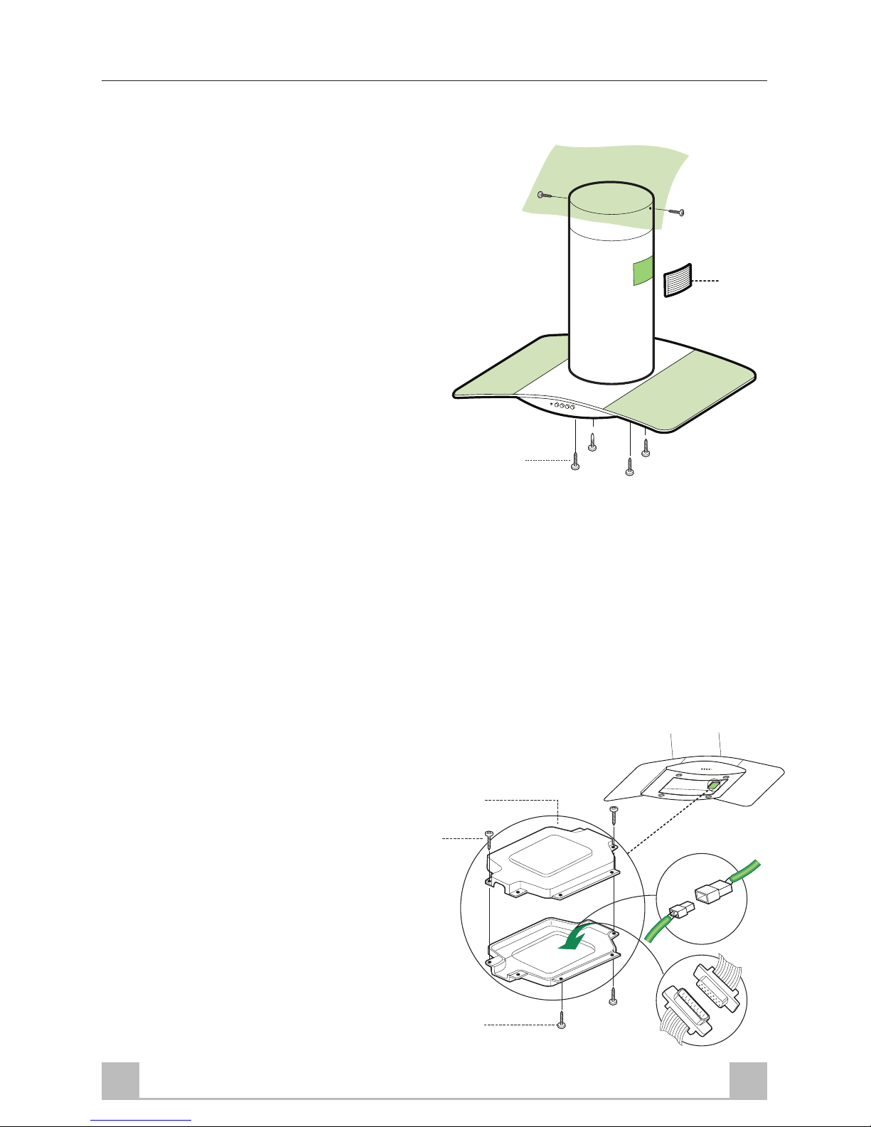
Connections
DUCTED VERSION AIR EXHAUST SYSTEM
When installing the ducted version, connect the hood to the chimney using either a flexible or rigid
pipe ø150 or 120 mm, the choice of which is left to the installer.
•To install a ø120 mm air exhaust connection,
insert the reducer flange 9on the hood body
outlet.
•Fix the pipe using the pipe clamps 25 provided.
•Remove any activated charcoal filters.
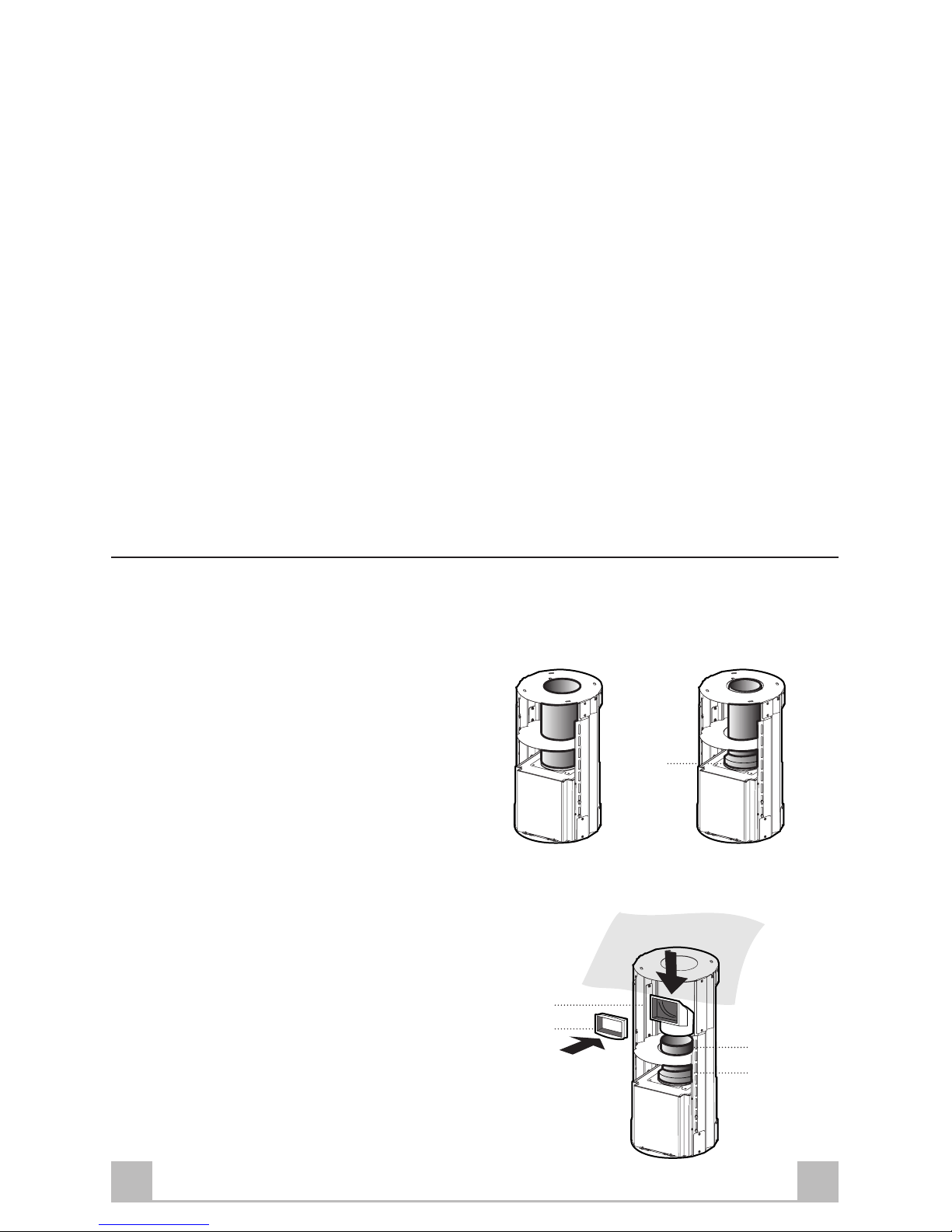
RECIRCULATION VERSION AIR OUTLET
•Insert reducer flange 9on the extractor outlet.
•Push fit the extension piece 14 onto the flange.
•Push fit connector 15 onto the extension piece.
•Insert extension piece/connector 14.1 laterally
on connector 15, ensuring that the outlet is in
line with the chimney intake.
9
ø 120ø 150
15
14.1 14
9