Facility Explorer FX16 Service manual

Technical Bulletin FX16 Master Controller
Issue Date May 14, 2007
©2007 Johnson Controls, Inc. www.johnsoncontrols.com
Code No. LIT-12011108
FX16 Master Controller
Introduction to FX16 Master Controller................................................4
FX16 Master Controller Key Concepts...............................................................5
FX16 Master Controller.....................................................................................................5
Installation...............................................................................................6
North American Emissions Compliance..............................................................................7
Installation Procedures .......................................................................................8
Mounting the FX16 Controller.............................................................................................8
Connection Details..............................................................................................................9
Connection Details for FX Slave Controllers - Distributed Application and Gateway
Objects - on Local Link Extension Bus .............................................................................13
Connection Details for I/O Expansion (XT91/XP91 Modules) on Local Extension Bus....15
Connection Details for the RS-485 N2 Open Card...........................................................16
LONWORKS Communication Card.....................................................................................20
RS-232C Communications Card.......................................................................................22
Connecting a Computer with the Null Modem Cable........................................................31
User Interfaces .................................................................................................................34
Integral MUI ......................................................................................................................37
FX Programming Key........................................................................................................40
Inputs and Outputs............................................................................... 43
Introduction.......................................................................................................................43
Inputs and Outputs Concepts...........................................................................44
Analog Inputs....................................................................................................................44
Digital Inputs.....................................................................................................................44
Analog Outputs.................................................................................................................44
Digital Outputs ..................................................................................................................44
Detailed Inputs and Outputs Procedures.........................................................45

FX16 Master Controller Technical Bulletin
2
FX16D and FX16X (Not Rev. A) Master Controller 24 VAC Power Connection...............45
FX16X Rev. A Master Controller 24 VAC Power Connection...........................................46
Analog Inputs....................................................................................................................47
Digital Inputs.....................................................................................................................53
Analog Outputs.................................................................................................................57
Digital Outputs ..................................................................................................................60
Extension Modules ...........................................................................................................63
Troubleshooting.................................................................................................65
Reading 9999 or Invalid from the Analog Inputs...............................................................65
Cannot Properly Read Current Sensors...........................................................................65
Operation...............................................................................................66
Introduction........................................................................................................66
Operation Concepts...........................................................................................66
Local Link Extension Bus..................................................................................................66
Distributed Application......................................................................................................67
Gateway Function.............................................................................................................67
Web Server.......................................................................................................................67
Communication Services..................................................................................................67
Supervisory Option ...........................................................................................................68
Alarm and Event Management .........................................................................................68
Data Trend Logging..........................................................................................................68
Time Scheduling...............................................................................................................68
User Interface ...................................................................................................................69
Application Configuration and Commissioning .................................................................69
Security.............................................................................................................................70
Application Upload/Download...........................................................................................70
Detailed Operation Procedures ........................................................................71
Local Link Extension Bus..................................................................................................71
Distributed Application......................................................................................................74
Gateway Function (LP-FX16X Rev. A Only).....................................................................77
Web Server.......................................................................................................................78
Communication Services..................................................................................................90
Supervisory Option ...........................................................................................................91

FX16 Master Controller Technical Bulletin 3
Event Management...........................................................................................................93
Data Trend Logging..........................................................................................................95
Time Scheduling...............................................................................................................96
User Interfaces .................................................................................................................98
Application Configuration and Commissioning ...............................................................100
FX Builder.......................................................................................................................101
FX CommPro N2/LON....................................................................................................105
Security...........................................................................................................................107
Application Upload/Download.........................................................................................108
Troubleshooting...............................................................................................114
GSM Modem Not Able to Send SMS #1.........................................................................114
GSM Modem Not Able to Send SMS #2.........................................................................114
Null Modem Connection Problems .................................................................................115
Multiple Null Modem Connections Error .........................................................................116
Specifications and Technical Data....................................................117
Ordering Codes................................................................................................117
Technical Specifications.................................................................................120
I/O Technical Details.......................................................................................................120
FX16 Master Controller...................................................................................................122
N2 Open Card.................................................................................................................123
LON Connection .............................................................................................................123
GSM Connection ............................................................................................................124
Programming Key...........................................................................................................125

FX16 Master Controller Technical Bulletin
4
Introduction to FX16 Master
Controller
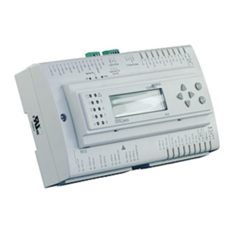
Figure 1: FX16 Master Controller with Display
The FX16 Master Controller is a high performance field controller in
the Facility Explorer system. The FX16 Master Controller is
specifically designed for commercial Heating, Ventilating, Air
Conditioning, and Refrigeration (HVACR) applications, such as chillers
and rooftops, indoor packaged air conditioning units, air handling units,
and close control units.
The controller has 27 physical inputs and outputs and supports a wide
range of temperature sensors and actuating devices. Additional physical
inputs and outputs may be achieved by adding the XT/XP expansion
modules on the local Extension bus.
The FX16 Master Controller can manage a distributed control
application with up to 16 FX slave controllers (FX05 Advanced, FX06,
FX07, FX14 or FX15 controllers). You can display and modify
parameters in the distributed control application from the optional
integral or remote mounted user interface.
The FX16 also features communication services to transmit event
notification messages via Short Messaging Service (SMS) or e-mail.
With its embedded Web server, you can browse and make adjustments
to parameters of the application from remote locations.

FX16 Master Controller Technical Bulletin 5
The FX16 Master Controller is fully configurable or programmable,
using the FX Tools Pro software package, for a wide range of
commercial HVACR applications.
The FX16 Master Controller is also available with a serial
communication card for the integration into an N2 Open or
LONWORKS® Building Automation network system.
Optional accessories make the FX16 Master Controller the ideal
solution for the building controls market. These include:
•N2 Open, plug-in communication card
•LON, plug-in communication card
•RS-232C, plug-in serial communication card
•Global System for Mobile Communications (GSM) modem
•Medium User Interface (MUI): integral, remote panel or wall-
mountable
FX16 Master Controller Key Concepts
FX16 Master Controller
The main features of the FX16 Master Controller include:
•fully programmable using FX Tools software package
•RS-485, N2 Open, or LON FTT10 plug-in communication card for
supervisory system
•as an alternative, an RS-232C port for a modem (or null modem)
connection
•DIN rail mounting
•removable screw connectors for servicing operations
•embedded Web server
•e-mail and SMS communications services manager
•Input/Output (I/O) expansion modules (up to 64 points)
•Distributed Application with up to 16 FX slave controllers
•optional Medium User Interface: integral, or remote panel or wall-
mounted
•multiple language support
•trend logging (up to 4 MB flash memory)
•easy commissioning via FX CommPro commissioning tool
•Programming Key for easy application uploading and downloading

FX16 Master Controller Technical Bulletin
6
Installation
This chapter takes you through the process of installing an FX16 Master
Controller.
!
WARNING: Risk of Electric Shock. Disconnect power supply before
making electrical connections. Contact with components carrying hazardous
voltage can cause electric shock and may result in severe personal injury or
death.
IMPORTANT: Use this FX16 controller only as an operating control. Where
failure or malfunction of the FX16 could lead to personal injury or damage to
the controlled equipment or other property, additional precautions must be
designed into the control system. Incorporate and maintain other devices such
as supervisory or alarm systems or safety or limit controls that are intended to
warn of, or protect against, failure or malfunction of the FX16 controller.
IMPORTANT: In North America, the controller is intended for installation with
Class 2 inputs and outputs only where no special electrical safety mounting
precautions are generally necessary. These controllers are UL- recognized as
Temperature Indicating and Regulating Equipment in accordance with UL 873
and UL Listed as Open Energy Management Equipment per UL 916.
IMPORTANT: Before specifying the FX16 for plenum applications, verify
acceptance of exposed plastic materials in plenum areas with the local
building authority. Building codes for plenum requirements vary by location.
Some local building authorities accept compliance to UL 1995, Heating and
Cooling Equipment, whereas others use different acceptance criteria.
IMPORTANT: Cables and wiring at Safety Extra-Low Voltage (SELV) and
Class 2 wiring (North America) must be separated from power line voltage
wiring. A minimum separation distance of 30 cm (12 in.) is recommended. Do
not run extra low voltage cables parallel to power line voltage cables for long
distances greater than 3 m (10 ft). Do not run extra low voltage wiring close to
transformers or high frequency generating equipment.

FX16 Master Controller Technical Bulletin 7
179 (7.05)
44 (1.73)
75 (2.95)
215 (8.46)
122 (4.8)
142 (5.59)
35 (1.38)
66 (2.6)
49 (1.93)
BB
Figure 2: Mounting Dimensions for FX16 (Shown with Integral User Display and
Screw Connectors), mm (in.)
Two different types of terminal connectors are available: spring clamp
or screw connectors. The screw connectors are included, whereas you
must order the spring clamp connectors separately. For details, see
Ordering Codes.
North American Emissions Compliance
United States
This equipment has been tested and found to comply with the limits for
a Class A digital device pursuant to Part 15 of the FCC Rules. These
limits are designed to provide reasonable protection against harmful
interference when this equipment is operated in a commercial
environment. This equipment generates, uses, and can radiate radio
frequency energy, and if not installed and used in accordance with the
instruction manual, may cause harmful interference to radio
communications. Operation of this equipment in a residential area is
likely to cause harmful interference, in which case the user is required
to correct the interference at his/her own expense.
Canada
This Class (A) digital apparatus meets all the requirements of the
Canadian Interference-Causing Equipment Regulations.
Cet appareil numérique de la Classe (A) respecte toutes les exigences du
Règlement sur le matériel brouilleur du Canada.

FX16 Master Controller Technical Bulletin
8
Installation Procedures
Follow these instructions to properly install and connect the FX16.
!
WARNING: Risk of Electric Shock. Disconnect power supply before
making electrical connections. Contact with components carrying hazardous
voltage can cause electric shock and may result in severe personal injury or
death.
Mounting the FX16 Controller
To mount the FX16 controller:
1. Snap the controller onto the 35 mm (1.38 in.) rail for DIN rail
mounting.
To release the controller, insert a screwdriver in Slot B and lift the
retaining clip. Since the retaining clip is spring-loaded, you can also
remove the controller without a screwdriver by carefully pushing the
controller up against the clip and then tilting the top forward to
release the top lugs from the DIN rail.
2. Make wiring terminations with detachable connectors.
The detachable connectors accept 1 x 1.5 mm2 (0.002 in.2)/14 AWG
cable. Two types of connector are available: screw connectors
shipped with the controller and cage clamp connectors ordered
separately.
Terminations to the Supervisor Link, Local Link Bus, and Remote
Display are made via the connectors provided with the controller.
3. Verify that the wiring has been correctly installed and that voltage
levels are appropriate for the various input signals according to the
application.
4. Set the jumpers and address switches of the controller. For more
information, see Jumper Details.
IMPORTANT: The Complementary Metal Oxide Semiconductor (CMOS)
circuits in the controller are sensitive to static electricity. Take suitable
precautions.

FX16 Master Controller Technical Bulletin 9
Connection Details
Wiring Diagram
-20T50
1
41 51 91787255
62
75
921 26 31
2
42 52 92797356
63
76
10 22 27 323
43 53 93807457 777154
61
11 23 28 334
44
12 24 29 345
45
13 25 30 356
46
147
47
158
48
AGND
DO1 Com
DO4 no
DO5 no
DO4/5Com
Earth
AO1
AO3
AO2
AO4
DO6/7/8Com
DO2 Com
DO3 Com
DO1 no
V~ Com
DO8 no
DO7 no
DO6 no
V~ Hot
FAIL no
FAIL Com
FAIL nc
AO Com
AO Com
AO Com
AO Com
DO2 no
DO3 no AGND
DI1
DI2
DI Com
DI7
DI5
DI8
DI3
DI6
DI V~ Hot
AGND
AGND
AGND
AGND
AI1
AI4
DI Com
DI4
DI Com
DI Com
DICom
DI V~ Com
AI2
AI5
AI3
AI6
Com
LL+
LL-
LL-
LL+
+16 V
Com
EXT V
EXT V
AVPS/EXT V
Digital Inputs
Analog Inputs
Extension Bus
To Supervisor
To Remote Display
Max
8(3)250V~
Digital Outputs
Analog Outputs
TB1 TB2
TB9
TB8
TB7
TB6
TB5
J2
J1
TB4
TB3
24 V~ 24 V~
JP1
1
2
3
AO V~ Com
AO V~ Hot
24 V~
!
FX16-006_112003
JP2
To Modem
(Optional
)
*
(Optional
)
*
(
)
*
Connectors JP1 and JP2 are in alternative
1:
2:
3:
N2 LON
Com
RT-
RT+
Not Used
NET B
NETA
Figure 3: Connection Details for the FX16 Master Controller
LP-FX16D0x-000C, LP-FX16X0x-000C, and LP-FX16X5x-000C (with 9 Relays)
In the FX16X Rev. A controllers, 24 VAC power is isolated at 500 V
from the internal processor circuits. This isolation enables the use of the
24 VAC power supply to the controller for the Analog Outputs (AOs)
and Digital (binary) Inputs (DIs), maintaining the isolation from the
internal processor circuits. Therefore, in the FX16X Rev. A controllers,
the external wiring of a 24 VAC power supply to the analog outputs
(terminals 79 and 80) and to the digital inputs (terminals 34 and 35) is
not required as the 24 VAC power supply is used internally for the
analog outputs and digital inputs. The terminals 34, 35, 79 and 80 still
exist on the FX16X Rev. A controllers to provide backward
compatibility when replacing a controller. In the FX16X Rev. A
controllers, terminals 35 and 80 are not connected to any internal
circuit. You can use terminals 34 and 79 as extra Com connections,
which are electrically connected to the 24 VAC Power Com.

FX16 Master Controller Technical Bulletin
10
Isolation Diagram
1
41 51 91787255 62 75
921 26 31
2
42 52 92797356 63 76
10 22 27 32
3
43 53 93807457 777154 61
11 23 28 33
4
44
12 24 29 34
5
45
13 25 30 35
6
46
147
47
158
48
Digital Inputs
A
nalog Input
s
Extension
Bus To Remote
Display
Digital Outputs Analog Outputs Power Supply
TB1
TB9
()
*
TB8TB7TB6TB5TB4TB3
J2
J1
To
Supervisor To
Modem
TB2
()
*
()
**
()
***
()
**
()
**
()
**
CPU
FX16-005_10 2003
Figure 4: FX16 Isolation Diagram
Figure 4 displays the isolation diagram for the FX16 controller. Use the
following list as a reference to understand the diagram:
•(*) Opto-isolated from the Central Processing Unit (CPU) circuits
(max. 500 V):
LP-FX16D and LP-FX16X (not Rev. A), when separate power
supply is used
LP-FX16X (Rev. A), with same power supply as controller
•(**) Not isolated from CPU (Analog Inputs, Local Link Extension
Bus, and Modem connections)
•(***) DC/DC converter with dielectric strength up to 500 V
•(****) Isolation of power supply from CPU is hardware model
dependent:
−Models LP-FX16D and LP-FX16X (not Rev. A) are not
isolated.
−Model LP-FX16X (Rev. A) is isolated (maximum 500 V).
FX16D and FX16 Controllers (Not Rev. A)
Consider the following information when you work with the
connections details for FX16D and FX16X controllers (not Rev. A):
•Analog Inputs (AIs) are not isolated from the processor circuits
(CPU) or the 24 VAC power supply.
(****)

FX16 Master Controller Technical Bulletin 11
•Analog Outputs (AOs) are opto-isolated and externally powered at
24 VAC. To maintain the opto-isolation, you must use a separate
power supply (3 VA) only for the analog outputs.
•Digital Inputs (DIs) are opto-isolated and externally powered at
24 VAC. To maintain the opto-isolation, you must use a separate
power supply (3 VA) only for the digital inputs.
•Digital Outputs (DOs) are isolated relays or opto-isolated triacs
supporting 24 VAC.
•N2 and LON communication ports are electrically isolated from the
digital inputs and analog/digital outputs and power supply.
•The RS-232C communication port is not isolated from the processor
circuits (CPU) or 24 VAC power supply.
FX16X Controllers (Rev. A)
Consider the following information when you work with the
connections details for the FX16X controllers (Rev. A):
•Analog Inputs (AIs) are not isolated from the Central Processing
Unit (CPU) but are isolated from the 24 VAC power supply.
•Analog Outputs (AOs) are opto-isolated from the CPU and
internally powered at 24 VAC from the power supply. An external
24 VAC power supply for the AOs is not required.
•Digital Inputs (DIs) are opto-isolated from the CPU and internally
powered at 24 VAC from the power supply. An external 24 VAC
power supply for the DIs is not required.
•Digital Outputs (DOs) are isolated relays or opto-isolated triacs
supporting 24 VAC
•N2 and LON communication ports are electrically isolated from the
digital inputs and analog/digital outputs and power supply.
•The RS-232C communication port is not isolated from the CPU but
is isolated from 24 VAC power supply.

FX16 Master Controller Technical Bulletin
12
Jumper Details
ed
c
ab
Battery
AI1 AI2 AI3 AI4 AI5 AI6
1 2 3
FX16-004
_
10 2003
Figure 5: Jumper Connections
Table 1: Jumper Connections
Diagram
Location Analog Input 0-20/4-20 mA Resistive, 0-10 V or Ratiometric
a AI1-AI6 Jumpers Closed Jumpers Open
(Default configuration)
Sensors Power Supply Audio Visual
Presentation Series
(AVPS) +5 V 20mA
EXT VDC+16 V 80mA (Total)
b Terminal Number 13 Pins closed between 1 and
2 Pins closed between 2 and 3
(Default configuration)
c Battery Type CR2032, average life time: 3 years, dispose of correctly with due regard for the
environment
d Pin strip closed: battery backup enabled
Pin strip open: battery disconnected (to preserve charge)
Jumper
d
is set to ON at the factory and should only be set to OFF if the controllers are to be kept
in storage without power for an extended period of time. The jumper must be set to ON before the
controllers is installed and powered up, otherwise backup function for RAM and Real-Time Clock
(RTC) is not enabled.
e Plug-in connector for optional cards insertion
f Hole for standoff for communication card
f

FX16 Master Controller Technical Bulletin 13
Connection Details for FX Slave Controllers - Distributed
Application and Gateway Objects - on Local Link Extension Bus
Figure 6 displays the connection details for the FX slave controllers on
the local extension bus.
Figure 6: Connection Details for the Slave Controllers

FX16 Master Controller Technical Bulletin
14
Consider the following information when you work with the
connections details for FX slave controllers:
•FX16 supports a maximum of 16 Facility Explorer slave controllers.
All slave controllers may be in a Distributed Application or
monitored by a Gateway Object, or you can use any combination
that does not exceed 16 devices.
•Slave model types for a Distributed Application: FX05 Advanced,
FX06, FX07, FX14, FX10 Advanced, FX15 Classic and FX15
Universal
•An FX controller used as a slave must have an RS-485 N2 Open
plug-in communication card installed.
•Slave model types for a Gateway Object: FX controller with N2
communication card, N2 Open Vendor (VND) device, or System 91
N2 controller (DX-9100 or TC-910x).
•The appropriate N2 bus serial address must be set on each slave
device.
•Maximum bus length is 1,200 m (4,000 ft).
•Install a repeater (for example, RP-9100-810x) to regenerate the
RS-485 signal. You install the repeater in case more than
31 N2 devices are connected on the local link extension bus and/or
the local link extension bus length is more than 1,200 m (4,000 ft).
•Install 220 ohm end-of-line resistors at each end of the bus line
when the bus length is greater than 100 m (330 ft). When the bus
length is fewer than 100 m (330 ft), insert only one 220 ohm resistor
at the FX16 Master Controller end only.
•The distributed application is downloaded to the FX16 Master
Controller. Then the FX16 Master Controller downloads the specific
parts of the application to the corresponding FX slaves.
•Devices connected and monitored by the Gateway object must be
programmed and/or configured independently.
•Slave devices can coexist with XT91/XP91 modules on the local
link extension bus.

FX16 Master Controller Technical Bulletin 15
Connection Details for I/O Expansion (XT91/XP91 Modules) on Local
Extension Bus Figure 7 displays the connection details for XT/XP modules on a local
extension bus.
Figure 7: Connection Details for the XT/XP Module
Consider the following information when you work with the
connections details for the XT91/XP91 Modules:
•Maximum XT modules are 4 x XT91D00 (or XT-9100).
•Maximum bus length is 1200 m (4000 ft).
•You must set appropriate N2 bus serial address on each XT module.
•Install a repeater (for example, RP-9100-810x) to regenerate the
RS-485 signal. You install the repeater in case more than
31 N2 devices are connected on the local link extension bus and/or
the local link extension bus length is more than 1,200 m (4,000 ft).
•Install 220-ohm end-of-line resistors at each end of the XT-Bus line
when the bus length is greater than 100 m (330 ft). When the bus
length is less than 100 m (330 ft), insert only one 220 ohm resistor
at the FX16 Master Controller end only.
XT91D00 XT91D00

FX16 Master Controller Technical Bulletin
16
•You can download the control application to the FX16 Master
Controller. Then the FX16 Master Controller downloads the specific
parts of the application to the corresponding XT modules.
•You must program and/or configure devices connected and
monitored by the Gateway object independently.
•XT91/XP91 modules can coexist with slave controllers on the local
link extension bus.
Connection Details for the RS-485 N2 Open Card
You can order the FX16 Master Controller with the RS-485 N2 Open
communication card, or you can order the N2 Open communication
card separately to insert the card at a later time. See Ordering Codes.
The RS-485 communication card allows the FX16 Master Controller to
connect to an N2 Open network of a building automation system.
Figure 8: N2 Open Plug-in Communication Card
Note: The N2 Open communication card for the FX16D and FX16X
(not Rev. A) controllers does not have S2 Communication Options
switch.

FX16 Master Controller Technical Bulletin 17
Figure 9: N2 Open Card Terminals
Installing the RS-485 N2 Communication Card
To install the RS-485 N2 communication card:
1. Turn off the controller (hot plug-in not allowed) and isolate all
high-voltage connections to the controller.
2. Open the controller by removing the two screws. See Figure 10.
Figure 10: Open the Controller
IMPORTANT: The CMOS integrated circuits in the controller and on the
communication card are sensitive to static current discharges. Take suitable
precautions.
3. Fit the standoff supplied with the card into the hole in the FX16
board (located close to the Local Link Bus terminals).
4. Press the connector pins into the communication board connector on
the FX16 board and press the card over the standoff to fit the card
firmly in position. See Figure 11.

FX16 Master Controller Technical Bulletin
18
Figure 11: Insertion of the N2 Open Card
5. On the upper DIP switch block (S2), set Switch 1:
Models with an integral display:
0 = baud rate and N2 Address set on DIP switches
1 (On) = baud rate and N2 Address set on controller display
Models without an integral display:
0 = baud rate and N2 Address set on DIP switches
6. If Switch 1 of S2 is set to 0, set the Baud Rate.
Note: For N2 communication with Metasys® supervisory systems,
you must select the baud rate of 9600 (factory default).
7. If Switch 1 of S2 is set to 0, set the N2 Address on the lower DIP
switch block (S1) in binary format (1 = ON). Examples are:
8 7 6 5 4 3 2 1
0 0 0 0 0 0 0 1 = N2 Address 1
0 0 0 0 0 0 1 1 = N2 Address 3
1 0 0 0 0 0 0 1 = N2 Address 129
1 1 1 1 1 1 1 1 = N2 Address 255
Note: Address zero is not supported on the N2 Open network. The
factory default address is 1.
8. Replace the control cover and secure the cover with the two screws.
9. Turn on the controller after you safely restore all connections.
IMPORTANT: If you change the N2 Address during a bench test with power
applied to the controller, cycle the power for a new address to become active
in the controller.
Align the pins as shown in figure

FX16 Master Controller Technical Bulletin 19
N2 Open Communication Card Connection
The FX16 controller cover displays 1, 2, and 3as the Supervisory Link
terminals. For the N2 Open Communication Card, the connections to
the RS-485 N2 Bus using the information in Table 2. The connections
are polarity sensitive; therefore, you must make the connections
correctly.
Table 2: RS-485 N2 Bus Connections
Supervisory Link N2 Bus
1 COM
2 RT -
3 RT +
Network Layout
For details about how to lay out the N2 network, refer to the
N2 Communication Bus Technical Bulletin (LIT-636018).

FX16 Master Controller Technical Bulletin
20
LONWORKS Communication Card
You can order the FX16 controller with the LONWORKS communication
card installed, or you can order the LONWORKS communication card
separately to insert at a later time. See Ordering Codes.
The LONWORKS communication card allows the FX16 to connect to a
LONWORKS free topology (FTT) network.
Figure 12: LON Plug-in Communication Card
Figure 13: LON Card Connection
Installing the LON Communication Card
To install the LON communication card:
1. Turn off the controller (hot plug-in not allowed) and isolate all high
voltage connections to the controller.
2. Open the controller by removing the two screws. See Figure 14.
Table of contents
Other Facility Explorer Controllers manuals
Popular Controllers manuals by other brands

UltraLift
UltraLift Prolift Advanced Programming guide

Timeguard
Timeguard MTLW3000 Installation & operating instructions

Atlas IED
Atlas IED Atmosphere AZM4 user manual

Magicfx
Magicfx FX-ARM CONTROLLER User and installation manual

Atlas IED
Atlas IED ASP-MG2240 General description

Ray-Dot
Ray-Dot RVS-22HA installation guide