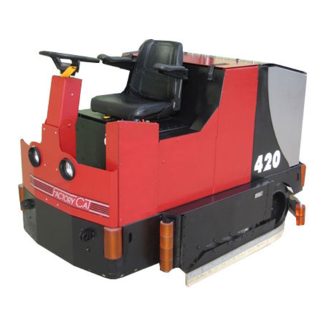
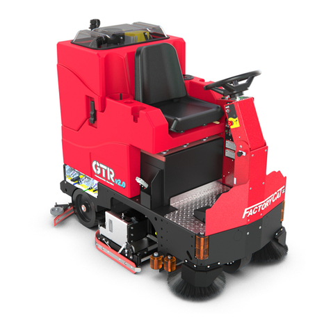
Factory Cat Pilot 28'' DISK User manual

Operating Instructions (EN)
Read these Instructions before
using the machine.
Read these Safety Messages
before using the machine.
Parts Manual
G
T
X
-
V
2
Se
r
i
e
s
Model GTX-V2
R.P.S. Corporation Phone: 1-800-634-4060
P.O. Box 368 Fax: 1-866-901-3335
Racine, Wisconsin 53401
2018 Version 1.0
Parts Manual
Series
Model
R.P.S. Corporation Phone: 1-800-634-4060
P.O. Box 368 Fax: 1-866-901-3335
Racine, Wisconsin 53401
2021 Version 2.0
www.factorycat.com
1711 South Street
Racine, WI 53404 (USA)
1-262-681-3583 V22.235
©2022 RPS Corporation, All Rights Reserved. FC-RIDER-V2-1-OP-EN
Models:
Pilot
26''-28'' Disk
25'' - 29'' Cylindrical
24'' & 28'' ORBITAL
GTX
26'', 30'' Disk
25'', 29'', 33'' Cylindrical
28'', 32' ORBITAL
GTR
30'', 34'' & 36'' Disk
29'', 33'', 37'' Cylindrical
N/A ORBITAL
V
VVVV2.02.02.0
VVVV2.02.02.0
175-1521
175-1521
175-1521

- 2 - FC-RIDERS-V2-OP-EN v22.235
INTRODUCTION
This manual is furnished with each new machine. This manual will allow the Operator to get the best performance out of
your RPS manufactured Scrubber-Drier, Sweeper, Burnisher, or Orbital Scrubber. Read this manual thoroughly before
operating or servicing the machine.
This machine will provide excellent performance, but the best results will be obtained at the most minimum costs if:
• The machine is regularly maintained - per the Authorized Local Distributor.
• The machine is operated with reasonable care and caution.
• The machine is maintained with manufacturer supplied parts.
LOCATE SERIAL NUMBER
The serial number of your machine is located on the lower half of the steering column of the machine.
AS OUR POLICY IS ONE OF CONSTANT IMPROVEMENT - ALL INFORMATION AND
SPECIFICATIONS ARE SUBJECT TO CHANGE WITHOUT NOTICE.

FC-RIDERS-V2-OP-EN v22.235 - 3 -
TABLE OF CONTENTS
Introduction 2
Locate Serial Number 2
Table Of Contents 3
Safety Messages 4
Safety Labels 6
Central command Dashboard controls
(Military, Legacy, Touch Screen) 7
Central Command Side Panel Controls 8
Legacy LCD Screen 9
Touch Screen (Optional) 10
Touch Screen Symbols (Optional) 11
Touch Screen Zone Operation (Optional) 12
Touch Screen Zone Programming (Optional)13
LCD Screen 14
steering col Controls 15
Service Cabinet 16
Spray Jet Controls (Optional) 17
Suds Controls (Optional) 18
ZerO3 Controls (Optional) 19
Manager Lock Outs 20
Headlights & Work-lights (Optional) 21
Side Broom System (Optional) 22
Legacy Econ Switch 23
Battery Setup 24
Remove Squeegee 25
Adjust Side Squeegee 26
Adjust Squeegee 27
Transportation - Forward 28
Transportation - Reverse 29
Fill Solution Tank 30
Operation - Scrubbing 31
Draining Recovery Tank 32
Draining Solution Tank 33
Flushing Recovery Tank 34
Clean Drain Saver & Vac System 35
Clean Cylindrical Hopper 36
Remove Disk Brushes 37
Remove Cylindrical Brushes 38
Parking Brake 39
Battery Chargers 40
P&G Controller Common Error Codes 41
Touch Screen Error Codes 42
Touch Screen Error Codes 43
Touch Screen Error Codes 44
Military - Status Light Codes 45
PM Sheet 46

- 4 - FC-RIDERS-V2-OP-EN v22.235
You will see four kinds of safety reminders in this manual:
DANGER
DANGER indicates a hazardous situation which, if not
avoided, will result in death or serious injury.
WARNING
WARNING indicates a potentially hazardous situation
which, if not avoided, could result in death or serious injury.
CAUTION
CAUTION indicates a potentially hazardous situation
which, if not avoided, could result in minor or moderate
injury or damage to this machine or nearby objects. CAU-
TION also can be used to alert against unsafe practices.
NOTICE
NOTICE indicates information considered important, but
not hazard-related. This safety message may be related to
property damage or warranty warnings.
Your safety, and that of others, is very important. Operating this machine safely is an important responsibility.
DO NOT OPERATE THIS MACHINE:
• Unless you are trained and authorized to do so by your RPS Authorized Local Distributor
• Unless you have read and understood this Operator’s Manual
• On surfaces with greater than an 2% / 3.49° grade
• On Loading Docks
WHEN OPERATING THIS MACHINE:
• Remove loose objects from the floor that could be projected from the rotating Brushes
• Keep your hands and feet away from the rotating Brushes
• Do not operate this machine where flammable liquids, vapors, or dust are present
• Use caution when maneuvering
• Wear PPE
BEFORE LEAVING THE MACHINE:
• Drain “clean” Solution & “dirty” Recovery solution into APPROVED drains
• Park the machine on a level surface
• Turn the machine off & remove key
BEFORE SERVICING THE MACHINE:
• Disconnect the Batteries
• Wear PPE
SAFETY MESSAGES
DANGER
Explosive hydrogen gas forms when Batteries are
charging. An open flame or spark can cause this gas
to explode. Serious personal injury or property damage
could occur. Only charge the Batteries in this machine
in a well ventilated area.
DANGER
Flammable materials can cause an explosion or fire.
Do not use flammable materials in Tank or pick up.

FC-RIDERS-V2-OP-EN v22.235 - 5 -
WARNING
The Batteries in this machine produce hazardous
voltage which can cause electrical shock, burns and/
or electrocution. Always disconnect Batteries before
servicing this machine.
WARNING
When climbing or descending ramps, always drive
machine forward. To avoid overturning the machine,
Do not back down ramps. Do not drive across inclines.
Do not turn while ascending or descending ramps.
Overturning the machine can cause serious injury or
death.
WARNING
Do not use water that exceeds 130°F / 54°C. If water
is above said temperature, this will void the Tank
Warranty.
WARNING
Do not park this machine on ramps or slopes. Always
park this machine on a level, hard surface. Do not
operate this machine outdoors or on uneven surfaces.
WARNING
The Batteries in this machine contain sulfuric acid,
which causes burns to skin. If battery acid contacts
clothing or skin, rinse the effected area with cold water
immediately. If battery acid gets on your face or in your
eyes, flush the area immediately with cold water and
seek medical attention.
WARNING
To avoid electrical shock, do not operate this machine
over electrical floor outlets.
WARNING
Dress safely. Do not wear rings or metal wrist watches
when servicing this machine, as they can cause an
electrical short circuit which can cause serious burns.
WARNING
Do not remove, paint over or destroy warning decals. If
warning decals become damaged, call 1-262-681-3583
for free replacements.
WARNING
Dress safely. Do not wear a neck tie, scarf, or any
loose or dangling clothing while operating this machine.
Loose or dangling clothing or neck-wear can tangle in
rotating parts, causing serious injury or death.
WARNING
Always turn off this machine before leaving it
unattended. Do not allow untrained persons to operate
this machine.
WARNING
NO RIDERS. Do not carry passengers on this machine.
Do not use this machine as a stepladder or work
platform.
WARNING
Understand the dynamic braking system before you
operate the machine on ramps. Machine may coast.
WARNING
Before you service a Battery, always wear face
protection, protective gloves and protective clothing.
Battery acid or battery explosion can cause serious
injuries.
CAUTION
To avoid damage to this machine, use only cleaning
solutions and replacement parts recommended by the
manufacturer.
CAUTION
Do not operate this machine if any parts have been
damaged or removed.
CAUTION
Always use the automatic battery charger provided
by the manufacturer of this machine to charge the
Batteries of this machine. It is designed to charge
the Batteries at the appropriate rate. If you must use
a different charger, disconnect the Batteries before
charging to avoid damage to the electronic speed
controller.
CAUTION
To avoid damage to the electronic control components
of this machine, Do not store this machine outdoors. Do
not pressure wash this machine.

- 6 - FC-RIDERS-V2-OP-EN v22.235
Read and obey all Safety Labels on your equipment. If you have questions about these labels, ask your supervisor.
These images indicate where on the Safety Labels are located. If ever the labels become illegible, worn off, or torn,
promptly report it to your supervisor and replace it.
SAFETY LABELS
DANGER

FC-RIDERS-V2-OP-EN v22.235 - 7 -
Military Grade
CENTRAL COMMAND DASHBOARD CONTROLS (MILITARY, LEGACY, TOUCH SCREEN)
1
3
3
4
4
5
15
5
6
6
6
6
777
88
8
999
10 10 10
5
5
4
4
3
3
2
2
13
13
13 2
2
2
2
1
12
11
11
12
1
11
1. Key Switch On (I) / Off (O)
2. Reverse Switch
3. Vac Switch
4. Solution Switch
5. Scrubdeck Switch
6. Down pressure Switch
7. Full Recovery Tank Light
8. Empty Recovery Tank Light
9. ZerO3 Light
10. Vac Clog Light
11. Military Battery Gauge / Hour Meter Combo
12. Military Down Pressure Gauge
13. Legacy LCD Screen
14. Legacy Quick Start Button
15. Status Indicator Light
Touch Screen
Touch Screen
Legacy
Legacy
Military Grade

- 8 - FC-RIDERS-V2-OP-EN v22.235
CENTRAL COMMAND SIDE PANEL CONTROLS
1. Head Lights/ Tail Lights
2. Side Brooms On (I) / Off (O)
3. Dual USB Voltmeter
4. Suds Switch 125:1/ 250:1/ Off (O)
5. ZerO3 On (I) / Off (O)
6. ZerO3 Circuit Breaker
7. Left Side Broom Circuit Breaker
8. Right Side Broom Circuit Breaker
9. Side Broom Lift Circuit Breaker
10. Negative BUSS Circuit Breaker
11. Positive BUSS Circuit Breaker
12. Left Brush Circuit Breaker
13. Right Brush Circuit Breaker
14. Vac Circuit Breaker
15. Solution Valve Circuit Breaker
16. Full Recovery Tank Indicator Light
17. Empty Solution Tank Indicator Light
18. ZerO3 Indicator Light
19. Vac Indicator Light
20. Solution Control Lever
21. Hour Meter Button
22. Dual Manager Lockout Solution/Downpressure
23. ECON switch Max (locked) Min (unlocked)
24. Status Indicator Light
25. Keyswitch
Military Grade (EX)
Military Grade (Pro/CRZ)
Touch Screen (EX)
Touch Screen (Pro/CRZ)
Legacy (EX)
Legacy (Pro/CRZ)
11
1
1
1
16
16
16
18
18
25
24
18
17
17
17
19
19
19
22
3
4
3
3
3
20
20
332
2
2
1
4
4
45
6
6
21
21
22
22
23
23
6
6
6
7
7
7
7 8 9 10 11
12 13 14 15
7
8
8
8
8
9
9910 11
10
10
11
11
910 11
5
5
5
5
67 8 9 10 11
12 13 14
15

FC-RIDERS-V2-OP-EN v22.235 - 9 -
** USE GREEN MENU SELECTION BUTTON ON CONTROL PANEL TO CHANGE SCREENS **
1. BATTERY LEVEL INDICATOR - Indicates the energy level remaining in the Batteries
(Shown on all menu displays)
2. SOLUTION OUTPUT INDICATOR - Indicates the gallons per minute (GPM) 0 - 1.0
3. SCRUBDECK DOWN PRESSURE INDICATOR - Sets the down pressure on the Brushes / Pads
4. SCRUB MOTORS ON - Indicates the Brush Motors are in operation
5. SOLUTION ON - Indicates the solution flow is ON
6. VACUUM ON - Indicates the Vacuum is ON
7. KEY SWITCH HOUR METER - Indicates total hours the machine has had keyswitch ON
8. TRANSPORT HOUR METER - Indicates total hours the drive system has been in operation
9. SCRUB BRUSH HOUR METER - Indicates total hours the brush motors have been in operation
10. VACUUM HOUR METER - Indicates total hours the vacuum motor has been used
11. DIAGNOSTIC CODE - Displays diagnostic code which helps troubleshoot issues
12. ERROR WARNING SYMBOL - Indicates when there has been a diagnostic code error
SCREEN #2 (MAINTENANCE)
10
9
8
7
SCREEN #3 (WITH ERROR CODE)
11
12
SCREEN #1 (OPERATOR)
1 2 3 4 5 6
LEGACY LCD SCREEN

- 10 - FC-RIDERS-V2-OP-EN v22.235
1. SOLUTION OUTPUT - Indicates the level of solution that is being dispensed when in operation, (0 = off, 1 = Low, 4 = High).
2. TECHNICAL / MANAGER SETUP - Access ‘Error Code History’ and Manager Programming
3. PROGRAMMED ZONES - Switch between preset solution and downpressure settings for varying applications
4. HOUR METERS - Displays all of the hour meters of the machine: Key Switch, Transport, Scrub Motors, and Vacuum Motor
5. DOWN PRESSURE OUTPUT - Indicates the level of downpressure that is being applied to the floor surface (1 = low, 4 = high).
6. BATTERY GAUGE - Indicates the level of battery charge available and volt meter
7. SUDS - (Onboard Chemical Dilution) indicator
8. ACTIVE VOLT & AMP DRAW - Indicates the live DC Volts (under battery gauge) and Amp draw (under systems) when machine
is running
9. AMP VAC CURRENT - Indicates Vac power consumption
10. TRANSPORT INDICATION - Green Forward & Red Rev
11. BRUSH DISK CURRENT - Indicates Brush power consumption
12. OPERATION MODE SELECTOR - Cycle through and select which operation mode you would like to work in
TOUCH SCREEN (OPTIONAL)
3
#1 NAME
SUDSSUDS
SUDSSUDS
3
#1
24.9
22.5 34.2
1
6
8 9 10
7
11 12
2 3 4 5

FC-RIDERS-V2-OP-EN v22.235 - 11 -
TOUCH SCREEN SYMBOLS (OPTIONAL)
3
#1 NAME
SUDSSUDS
Setup Hour Meters Zone Lock
Locked Unlocked
Forward Transport Motor
Working Active Inactive
Reverse Transport Motor
Working Active Inactive
Solution Flow
Working Active Inactive
Vacuum Motor
Working Active Inactive
Solution Setting
#0 #1 #2 #3 #4
Down Pressure Setting
#1 #2 #3 #4
Mode Selection
Transport Only Single Scrub Double Scrub Vacuum Only
Scrub Deck Motor(s)
Working Active Inactive
Suds
250:1 Dilution 125:1 Dilution Inactive
SUDS SUDS SUDS

- 12 - FC-RIDERS-V2-OP-EN v22.235
The touch screen is designed to be programmed to three specific
zones. Each zone can be named and custom programmed or even
disabled if not needed.
The zone you are working in is highlighted as indication. In Figure 1.
the zone selected is Light Duty.
Figure 2. shows Zone 3 “locked out” by the indicator lock icon.
Figure 3. shows Zone 1 “Light Duty” Factory Configuration.
Water = 1
Downpressure = 2
Drive Speed = 70%
Vac Motor = 80%
Figure 3. shows Zone 2 “Daily” Factory Configuration.
Water = 2
Downpressure = 3
Drive Speed = 90%
Vac Motor = 90%
Figure 3. shows Zone 3 “Heavy Duty” Factory Configuration.
Water = 3
Downpressure = 4
Drive Speed = 100%
Vac Motor = 100%
TOUCH SCREEN ZONE OPERATION (OPTIONAL)
3
#1 NAME
SUDSSUDS
3
LIGHT DUTY
SUDSSUDS
3
LIGHT DUTY
SUDSSUDS
% %
LIGHT DUTY
3
% %
DAILY
3
% %
HEAVY DUTY

FC-RIDERS-V2-OP-EN v22.235 - 13 -
To program the 3 Zones, press
From here you will be prompted with a passcode screen. Enter the
manager passcode 349 to get access to setup.
Once you have entered the password, you will see the Figure 3.
screen where you can alter the name, solution output, down-pressure
setting, scrubbing speed, and vacuum power.
Alternatively you can lock the Zone out from this screen, to prohibit
operator use.
Once any of the 3 “Zones” is locked the remaining zones are no lon-
ger adjustable either by the operator.
To alter the name of a Zone, simply click on the black name box and
a full keyboard will appear as Figure 4. shows. Enter new name and
save your work with the Green save icon.
TOUCH SCREEN ZONE PROGRAMMING (OPTIONAL)
3
#1 NAME
SUDSSUDS
3
LIGHT DUTY
SUDSSUDS

- 14 - FC-RIDERS-V2-OP-EN v22.235
** USE GREEN MENU SELECTION BUTTON ON CONTROL PANEL TO CHANGE SCREENS **
1. BATTERY LEVEL INDICATOR - Indicates the energy level remaining in the Batteries
(Shown on all menu displays)
2. SOLUTION OUTPUT INDICATOR - Indicates the gallons per minute (GPM) 0 - 1.0
3. SCRUBDECK DOWN PRESSURE INDICATOR - Sets the down pressure on the Brushes / Pads
4. SCRUB MOTORS ON - Indicates the Brush Motors are in operation
5. SOLUTION ON - Indicates the solution flow is ON
6. VACUUM ON - Indicates the Vacuum is ON
7. KEY SWITCH HOUR METER - Indicates total hours the machine has had keyswitch ON
8. TRANSPORT HOUR METER - Indicates total hours the drive system has been in operation
9. SCRUB BRUSH HOUR METER - Indicates total hours the brush motors have been in operation
10. VACUUM HOUR METER - Indicates total hours the vacuum motor has been used
11. DIAGNOSTIC CODE - Displays diagnostic code which helps troubleshoot issues
12. ERROR WARNING SYMBOL - Indicates when there has been a diagnostic code error
SCREEN #2 (MAINTENANCE)
10
9
8
7
SCREEN #3 (WITH ERROR CODE)
11
12
SCREEN #1 (OPERATOR)
1 2 3 4 5 6
LCD SCREEN

FC-RIDERS-V2-OP-EN v22.235 - 15 -
1. 2. 3.
EMERGENCY
STOP
STEERING COL CONTROLS
2
3
1

- 16 - FC-RIDERS-V2-OP-EN v22.235
SERVICE CABINET
18
19 20 21 22 23
18. VACUUM
DISCHARGE:
Water passed through the
Vacuum Motor will be visible
in the reservoir and excess
will flow from the blue hose.
Indicates service required.
19. VAC BOX UNLOADER:
Unloader valve for the Yellow
Vac Box. Water present in the
Yellow Vac Box will drain when
vacuum is off.
20. SOLUTION FILTER:
Standard Solution Feed Filter
for scrubdeck.
21. SUDS DRAIN:
Drain detergent from Suds
reservoir.
22. ZERO3 FILTER:
Optional ZerO3 (O3+) Ozone
System Solution Filter.
23. BATTERY DRAIN:
Drain any fluid from Poly
Battery Box.

FC-RIDERS-V2-OP-EN v22.235 - 17 -
25.
SPRAY JET CONTROLS (OPTIONAL)
24

- 18 - FC-RIDERS-V2-OP-EN v22.235
SUDS
SUDS
SUDS
Touch Screen View I - OFF
Touch Screen View 250:1
Touch Screen View 125:1
SUDS CONTROLS (OPTIONAL)
250:1 (~0.5oz / gal [~4ml / 1L]) - “Single Dose”
125:1 (~1oz / gal [~8ml / 1L]) - “Double Dose”
Legacy View O - OFF

FC-RIDERS-V2-OP-EN v22.235 - 19 -
ZerO3 CONTROLS (OPTIONAL)
Turn regular solution OFF, when using ZerO3
Aqueous Ozone. Legacy Only
Indiactor Light O - OFF
Indicator Light I - ON

- 20 - FC-RIDERS-V2-OP-EN v22.235
MANAGER LOCK OUTS
CONTROLLING MANAGER LOCK OUTS:
When the key is in the LOCKED position, keys can be removed and Solution OR Down-pressure cannot be adjusted.
UNLOCKED LOCKED
Other manuals for Pilot 28'' DISK
1
This manual suits for next models
2
Table of contents
Other Factory Cat Scrubber manuals
Popular Scrubber manuals by other brands

ICE COBOTICS
ICE COBOTICS RS26 Plus Care & Cleaning

HAWK ENVIRONMENTAL
HAWK ENVIRONMENTAL AirWash MultiPro product manual

Tennant
Tennant 8410 Service manual

Windsor
Windsor Walk Behind Scrubber 10052250 operating instructions

PowerPoint
PowerPoint P21561XBSS Installation - use - maintenance

DeWalt
DeWalt DWV900L manual