Factory CHRISTEN EAGLE II User manual

Kit features.
• Ready-made—minimalassembly&finishingrequired.
• Ready-coveredcovering.
• Photo-illustratedstep-by-stepAssemblyManual.
MadeinVietnam.
Specifications
Wingspan---------------------------------------53.9in-----------------------------137cm.
Wing area---------------------------------------922.3sq.in------------------59.5sq.dm.
Weight--------------------------------------------8.4-9.9 lbs--------------------3.8-4.5kg.
Length--------------------------------------------47.4 in---------------------------120.5cm.
Recommendedenginesize----------0.75-.91cu.in-------------------------2-stroke.
--------------0.91-1.00 -1.25cu.in---------------- 4-stroke.
ELECTRIC CONVERSION : OPTIONAL.
Radio System required 6 channel with 6 digital servos.
Flyingskilllevel---------------------Intermediate/advanced.
ASSEMBLY MANUAL
MS:104
CHRISTEN
EAGLE II

CHRISTEN EAGLE II Instruction Manual.
2
INTRODUCTION.
Thank you for choosing the CHRISTEN EAGLE II ARTF by SEAGULL MODELS. The
CHRISTENEAGLEII wasdesignedwiththeintermediate/advancedsportflyerinmind.Itisa semi
scale airplane whichiseasytoflyandquicktoassemble.Theairframeisconventionallybuiltusing
balsa,plywood tomake it strongerthanthe average ARTF,yet the designallowsthe aeroplane to
bekeptlight.Youwillfindthatmostoftheworkhasbeendoneforyoualready.Flyingthe CHRISTEN
EAGLE II is simply a joy.
This instruction manual is designed to help you build a great flying aeroplane. Please read this
manual thoroughly before starting assembly of your CHRISTEN EAGLE II . Use the parts listing
below to identify all parts.
WARNING.
Please be aware that this aeroplane is not a toy and if assembled or used incorrectly it is
capable of causing injury to people or property. WHEN YOU FLY THIS AEROPLANE YOU
ASSUME ALL RISK & RESPONSIBILITY.
If you are inexperienced with basic R/C flight we strongly recommend you contact your R/C
supplierandjoinyourlocalR/CModelFlyingClub.R/CModelFlyingClubsofferavarietyoftraining
proceduresdesignedtohelpthenew pilot on his way to successfulR/Cflight.Theywillalsobeable
to advise on any insurance and safety regulations that may apply.
ADDITIONAL ITEMS REQUIRED.
0.75-.91 2- stroke engine.
0.91-1.00-1.25 4- stroke engine.
Computer radio with six digital
servos.
Glow plug to suit engine.
Propeller to suit engine.
Protective foam rubber for radio
system.
Siliconefuel line.
TOOLS & SUPPLIES NEEDED.
Thick cyanoacrylate glue.
30 minute epoxy.
5 minute epoxy.
Hand or electric drill.
Assorted drill bits.
Modellingknife.
Straight edge ruler.
2mm ball driver.
Phillips head screwdriver.
220 grit sandpaper.
90° square or builder’s triangle.
Wire cutters.
Masking tape & T-pins.
Thread-lock.
Paper towels.
PARTS LISTING.
FUSELAGE ASSEMBLY
(1) Fuselage.
(1) Canopy hatch.
WING ASSEMBLY
(2) Right wing half with pre-installed
aileron.
(2) Left wing half with pre-installed
aileron.
(2) Aluminium dihedral brace.
Tail section assembly
(1) Horizontal stabilizer with pre-
installedelevatorhalves.
(1) Vertical stabilizer with pre-
installed rudder halves.
Some more parts.
HARDWAREPACK
COWLING
Landinggear.....

www.seagullmodels.com
3
NOTE: To avoid scratching your new aero-
planewesuggestthatyoucoveryour
workbench with an old towel. Keep a
couple of jars or bowls handy to hold
the small parts after you open the
bags.
Pleasetrialfitallparts.Makesureyou
have the correct parts and that they
fit and are aligned properly before
gluing! This will ensure proper as-
sembly as the CHRISTEN EAGLE II
is made from natural materials and
minor adjustments may have to be
made.
The paint and plastic parts used in
this kit are fuel proof. However, they
arenottolerantofmanyharshchemi-
cals including the following: paint
thinner, cyano-acrylate glue accel-
erator,cyanoacrylategluede-bonder
andacetone.Donot let these chemi-
calscome incontact withthe colours
onthecoveringand the plastic parts.
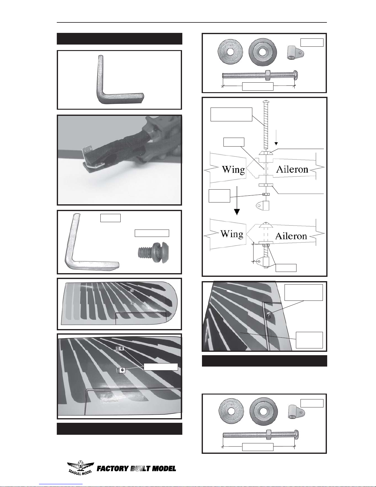
1) Carefully remove the aileron from one
of the wing panels. Note the position of the
hinges.
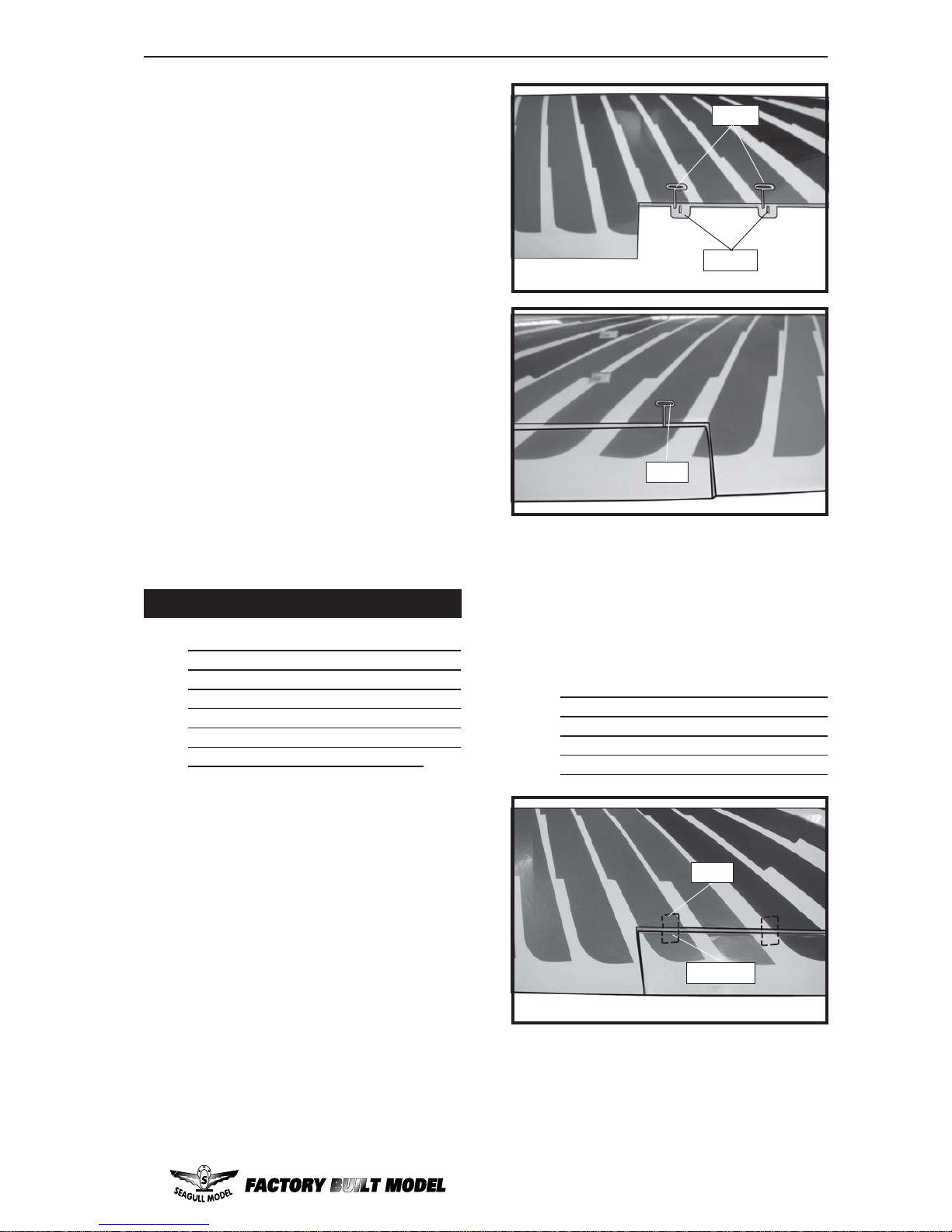
2)Removeeachhinge from the wingpanel
and aileron and place a T-pin in the center of
each hinge. Slide each hinge into the aileron
untiltheT-pin is snug against the aileron. This
will help ensure an equal amount of hinge is
oneithersideofthehingelinewhentheaileron
is mounted to the wing panel.
HINGING THE AILERONS.
The control surfaces, including the
ailerons, elevators, and rudder, are
prehinged with hinges installed, but the
hinges are not glued in place. It is
imperativethat you properly adhere the
hingesin place per the stepsthat follow
using a high-quality thin C/A glue.
Note:
T-pin.
3) Slide the aileron on the wing panel until
there is only a slight gap. The hinge is now
centered on the wing panel and aileron.
Remove the T-pins and snug the aileron
against the wing panel.A gap of 1/64” or less
shouldbe maintained betweenthe wing panel
andaileron.
Hinge.
T-pin.
C/Aglue.
4)Deflect the aileron and completely
saturate each hinge with thin C/A glue. The
aileronsfrontsurfaceshouldlightly contact the
wing during this procedure. Ideally, when the
hinges are glued in place, a 1/64” gap or less
will be maintained throughout the lengh of the
aileron to the wing panel hinge line.
Note: The hinge is constructed of a special
material that allows the C/A to wick or
penetrateanddistributethroughout the
hinge, securely bonding it to the wood
structureof the wingpanel and aileron.
5)Turnthe wingpanelover and deflectthe
aileron in the opposite direction from the
opposite side. Apply thin C/A glue to each
hinge,makingsure that theC/Apenetratesinto
both the aileron and wing panel.
T-pin.

CHRISTEN EAGLE II Instruction Manual.
4
Glue the elevator hinges in place using the
same techniques used to hinge the ailerons.
HINGING THE ELEVATORS.
8)Afterbothailerons are securely hinged,
firmly grasp the wing panel and aileron to
make sure the hinges are securely glued and
cannot be pulled out. Do this by carefully
applying medium pressure, trying to separate
the aileron from the wing panel. Use caution
not to crush the wing structure.
7) Repeat this process with the other wing
panel, securely hinging the aileron in place.
6) Using C/A remover/debonder and a
papertowel,remove any excessC/A glue that
may have accumulated on the wing or in the
aileronhinge area.
HINGING THE RUDDER.
Glue the rudder hinges in place using the
same techniques used to hinge the ailerons.
Work the aileron up and down several
times to “work in” the hinges and check
for proper movement.
Note:
LOWER MAIN WING( UPPER SIZE).
M3x10mm.
M3x10mm.
M3x10mm.
4 pcs.

www.seagullmodels.com
5
M3x10mm.
UPPER MAIN WING( LOW SIZE).
M3x10mm.
M3x10mm.
Aileron control horn installation: See pictures
below.
AILERON CONTROLHORN
M3LOCK
NUT.
ALUMINUMWASHER.
ALUMINUMWASHER.
CONTROLHORN
M3 SCREW.
Epoxy.
Epoxy.
ELEVATOR CONTROL HORN.
Install the elevator control horn using the
same method as with the aileron control
horns.
2 sets.
3x35mm.
4 pcs.
18mm.
Wing
bottom.
Aileron
control horn.
2 sets.
3x40mm.

CHRISTEN EAGLE II Instruction Manual.
6
AluminumWasher.
CONTROL HORN M3
M3LOCKNUT.
Epoxy.
AluminumWasher.
Rudder control horn:
Using the same techniques used aileron
control horn. See picture below.
16mm.
Epoxy.
RUDDER CONTROL HORN.
Horizontal
Stabilizer.
Elevator control horn.
Horizontal
Stabilizer. Elevator.
2 sets.
3x45mm.
CONTROL HORN
M3SCREW.
ALUMINUMWASHER.
ALUMINUMWASHER.
M3LOCK NUT.
EPOXY.
FUSELAGE Rudder
18mm.
EPOXY.
Fuselage. Rudder.
Ruddercontrolhorn.
See pictures below.Make yourself the
template of your engine on paper.
ENGINE MOUNT INSTALLATION.
M4x30mm.

www.seagullmodels.com
7
2) Usinga modeling knife,cut onelength
ofsiliconfuel line. Connect oneend of the line
tothe weighted fuelpick up andthe other end
to the nylon pick up tube.(The silicon tube is
not included).
Carefully use a lighter or heat gun to
permenently set the angle of the vent tube.
3) Carefully bend the second nylon tube
up at a 45º angle. This tube is the vent tube.
Venttube
Fuelfill tube
Fuel pick up tube.
Mark and drill 4 holes for engine mount.
Insert 4 blind nuts to firewall.
1) Using a modeling knife, carefully cut
off the rear portion of one of the 3 nylon tubes
leaving 1/2” protruding from the rear of the
stopper. This will be the fuel pick up tube.
INSTALLING THE STOPPERASSEMBLY.
M4x30mm.
Important: When the stopper assembly is in-
stalled in the tank, the top of the vent tube
should rest just below the top surface of the
tank. It should not touch the top of the tank.
4) Test fit the stopper assembly into the
tank. It may be necessary to remove some of
the flashing around the tank opening using a
modeling knife. If flashing is present, make
sure none falls into the tank.
5) With the stopper assembly in place,
the weighted pick-up should rest away from
therear of the tank andmove freely inside the
tank. The top of the vent tube should rest just
below the top of the tank. It should not touch
the top of the tank.
6) When satisfied with the alignment of
the stopper assembly tighten the 3 x 20mm
machine screw until the rubber stopper ex-
pands and seals the tank opening. Do not
overtighten the assembly as this could cause
the tank to split.
5.5mm.
M3X15mm.

CHRISTEN EAGLE II Instruction Manual.
8
Fuel pick-up tube. Fuel filltube.
Vent tube.
1C/Aglue.
FUEL TANK INSTALLATION.
You should mark which tube is the vent
and which is the fuel pickup when you
attach fuel tubing to the tubes in the stopper.
Once the tank is installed inside the fuselage,
it may be difficult to determine which is which.
Glow Engine.
12
1) Assemble and mounting the wheel
pants as shown in the following pictures.
Blow through one of the lines to en-
sure the fuel lines have not become
kinked inside the fuel tank compartment.
Air should flow through easily.
WHEEL AND WHEEL PANTS.
Fueltank.
2
C/Aglue.
1

www.seagullmodels.com
9
wheel collar.
wheel.
Axle.
Washer. M3.
wheel Pant.
wheel.
M3.
M3.
wheel collar.
nut. Axle.
Washer.
M3.
C/Aglue.
LandingGear. wheel Pant.
Lockerglue.
2) A drop of C/A glue on the wheel collar
screws will help keep them from coming lose
duringoperation.
Repeat the process for the other wheel.
1) The blind nuts for securing the landing
gearare already mounted insidethe fuselage.
2) Usingthe hardwareprovided, mount the
main landing gear to the fuselage.
INSTALLING THE MAIN LANDING GEAR.
(2)Wheel Collar.
Axle.
Wheel. Nut.
Nut.
(2)Washer.
Trimandcut.

CHRISTEN EAGLE II Instruction Manual.
10
M4 x 20mm.

www.seagullmodels.com
11
Battery.
Tiewrap.
INSTALLING THE BATTERY.
MOUNTING THE ENGINE.
4.2mm diameter.
C/Aglue.
140mm.
COWLING.
Pushrod wire.
Pushrod wire.
Trim and cut.
Trim and cut.
Trim and cut.
M4 x 30mm.
M3 x 10mm.

CHRISTEN EAGLE II Instruction Manual.
12
Electric motor.
1
2
Epoxy.
Epoxy.
5.2mm diameter.
Electric Conversion (Ep Power)
(OPTION).
M3 x 10mm.
2
1
3
2
Epoxy.
M3 x 10mm.
4
Balsa block.
12140mm

www.seagullmodels.com
13
Electric motor.
Battery.
Battery.
The propeller should not touch any part of the
spinner cone. If it does, use a sharp model-
ing knife and carefully trim away the spinner
conewherethepropeller comes in contactwith
it.
Install the spinner backplate, propeller
and spinner cone.
INSTALLING THE SPINNER.
M4 x 15mm.
M3x15mm.
Speed control.
4

CHRISTEN EAGLE II Instruction Manual.
14
AILERONPUSHROD HORN INSTALLATION
Wing.
Aileron.
M3 lock nut.
M3clevis.
70mm.
94mm.
Aileron.
Wing.
Aileron.
Attach the string to the servo lead and carefully thread it though the wing.
String.
Small Weight.
Wing.
String.
Small Weight.
Wing rib. INSTALLING THE AILERON SERVOS.

www.seagullmodels.com
15
Switch.
INSTALLING THE FUSELAGE SERVO.
INSTALLING THE SWITCH.
Installtheswitch into theprecut hole inthe
side, in the fuselage.
THROTTLE SERVO ARM INSTALLATION.
1) Install adjustable servo connector in
the servo arm as same as picture below:
AdjustableServo
connector.
Servoarm.
Nut.
Draw center line.
When cutting through the covering to re-
move it, cut with only enough pressure
toonly cutthrough the covering itself. Cutting
into the balsa structure may weaken it.
INSTALLINGTHE HORIZONTALSTABILIZER.
Wing.
Aileron.
M3lock nut.
Repeat the procedure for the other wing.
Throttleservo.
Elevatorservo.
Rudderservo.
Elevatorservo.
Elevatorservo.
Rudderservo. Elevator servo.
Throttleservo.
remove covering.

CHRISTEN EAGLE II Instruction Manual.
16
INSTALLING THE VERTICALSTABILIZER.
Pen.
Trim and cut.
Epoxy.
Trim and cut.
Epoxy.
Epoxy.

www.seagullmodels.com
17
ELEVATOR - RUDDER PUSHROD -
CONTROL HORN INSTALLATION.
M2clevis. M2 Lock nut.
Attach to servo arm in fuselage. Attach to elevator - rudder control horn.
Maskingtape.
Elevator control horn .
Elevator pushrod .
Hinge. C/Aglue. Elevatorcontrol horn
M2lock nut.
Metalclevis
Rudder control horn .

CHRISTEN EAGLE II Instruction Manual.
18
Rudder. Elevator Pushrod.
Throttle.
Servoelevator.
MOUNTING THE TAIL WHEEL.
Seepicturebelow.
M3 x 12mm.
Epoxy.
1
1
Trimandcut.
servo rudder
M3 x 12mm.
1

www.seagullmodels.com
19
2pcs.
ATTACHMENT WING (LOWER WING).
1
INSTALLING THE CANOPY HATCH.
1) Plug the six servo leads and the switch
lead into the receiver. Plug the battery pack
lead into the switch also.
2) Wrap the receiver and battery pack in
the protective foam rubber to protect them
from vibration.
3) Route theantenna in the antennatube
inside the fuselage and secure it to the bot-
tom of fuselage using a plastic tape.
INSTALLING THE RECEIVER.
Receiver.
Wing bolts.
20 pcs.
M3 x10mm.

CHRISTEN EAGLE II Instruction Manual.
20
1
1
M3 x 10mm.
M3 x 10mm.
M3 x 20mm.
M3 x 10mm.
This manual suits for next models
1
Table of contents
Other Factory Toy manuals