S40
VIGILO 2250
VIGILO 2280
8
VIGILO 2250
VIGILO 2280
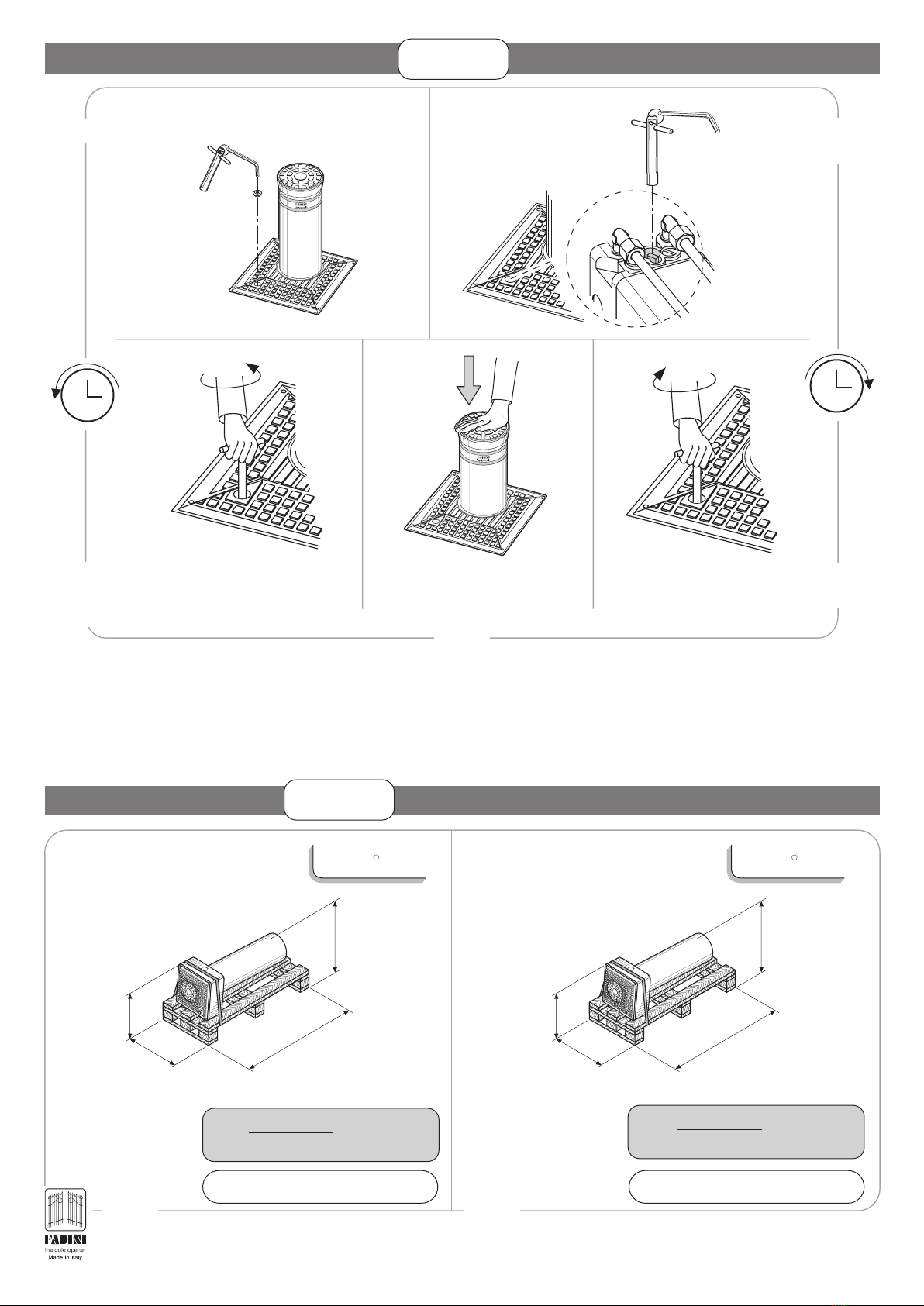
PIC. 15
4x1mm
2
2x1mm
2
4x1mm
2
4x1,5mm
2
8
9
7
10
6
11
1
2
3
4
5
6
7
4x1mm
2
4x1mm
2
2x1mm
2
PIC. 14
®
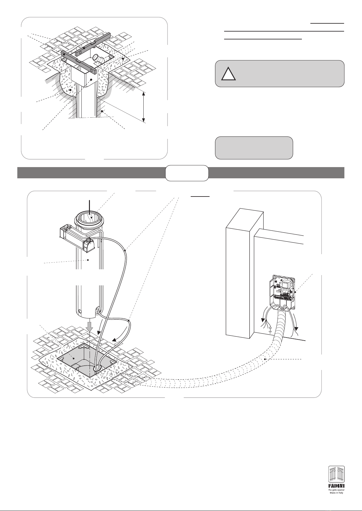
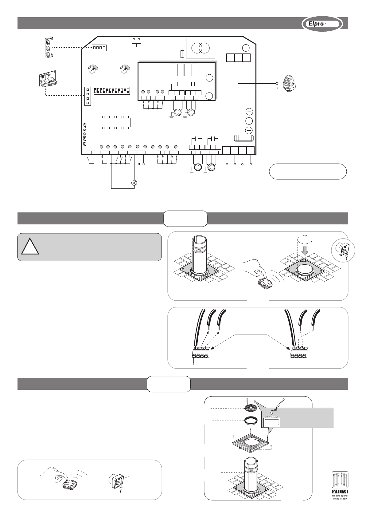
ARRANGING THE SAFETY AND SIGNALLING ACCESSORIES
All safety and control accessories must be installed at certain
distances from the operator in order to obtain effective
installation. Connect to earth.
ARRANGEMENT OF THE PHOTOELECTRIC CELLS
The photoelectric cells must be installed at a minimum
working distance as indicated in Pic. 15.
ARRANGING VISUAL 344
The 2 or 3-module Visual 344 cabinet is a metal accessory
used to house the Elpro S40 in exposed positions, in those
installation situations in which the programmer cannot be
wall- or recess-mounted. It has also been designed for the
installation of possible control accessories such as intercom
systems or key switches, in the immediate vicinity of the
Vigilo 2250 or Vigilo 2280 (pic. 15).
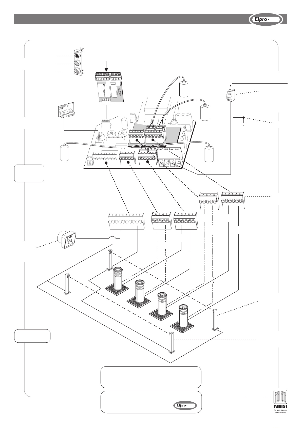
Before making electric connections, carefully read the wiring diagrams attached: Elpro S40 electronic programmer instruction booklet
- Drwg. 4555.
- Power supply, electric motor and flashing light wiring must be made using cables with 1.5 mm2sections, for a maximum distance of
50 m. For distances of over 50 metres, we recommend using electric wires with sections of 2 mm2.
- For the Photoelectric cells, button switches and accessories, electric wires with 1 mm2sections may be used.
- The whole electrics system must be earthed.
INSTALLATION WIRING
Components
1 - MIRI 4 flashing light with built-in aerial
2 - Wall-mounted Astro 43 radio receiver
3 - Elpro S40 Electronic programmer
4 - Differential circuit breaker switch
(sensitivity 30mA, protection 6-10A)
5 - Junction box, electric wires
6 - Polo 44 photoelectric cell projector
7 - Polo 44 photoelectric cell receiver
8-Prit 19 key switch
9-Two-light 230V traffic light
10 - Vigilo 2250 or Vigilo 2280 retractable traffic control post
11 - Astro 43/2 Piccolo transmitter
IMPORTANT:
The whole electric system must be earthed (Pic. 15).
230V ±10%
50 Hz
2x1mm
2
RGB cable
min 1
.
0 m
Prit 19
Earthing
4x1mm
2
- Motor
2x1mm
2
- Limit switch