manuals.online logo
Brands
  1. Home
  2. •
  3. Brands
  4. •
  5. Fagor
  6. •
  7. Media Converter
  8. •
  9. Fagor HTT 101 User manual

Fagor HTT 101 User manual

HTT 101
HDMI/YPbPr/S
Encoder Modulator
HTT 101
HDMI/YPbPr/S
-Video/AV to
DVB
Encoder Modulator
DVB
-T
TABLE O CONTENTS
1. SPECIFICATIONS .............................................................................................................................. 3
1.1 Product Overview ..................................................................................................................... 3
1.2 Appearance and Description .................................................................................................... 3
1.3 Syste Diagra ........................................................................................................................ 4
1.4 Characteristics .......................................................................................................................... 4
2. Installation Guide and Safety Instructions ..................................................................................... 5
2.1 Safety Instructions .................................................................................................................... 5
2.2 Installation ................................................................................................................................ 5
3. Operation ....................................................................................................................................... 7
3
1. SPECI ICATIONS
1.1 Product Overview
HTT Home encoder & modulator allows audio/video signal input in TV distributions with
applications in ho e entertain ent, surveillance control, hotel Digital Signage, shops etc.
It is an all-in-one device integrating MPEG4 AVC/H.264 encoding and DVB-T odulating to
convert input signals to DVB-T RF out in the frequency range of 30~960MHz.
The signals source could be fro satellite receivers, closed-circuit television ca eras, Blue-ray
players, and antenna etc. its output signal is to be received by DVB-T standard TVs or DVB-T
STBs etc.
1.2 Appearance and Description
Grounding: to connect the earth cable
DC 12V: power input
HDMI: HDMI strea input supporting HD signals
YPbPr/S-Video/AV: YPbPr/S-Video/AV signal input through a VGA adapter cable
R in: RF Loop-through input (10dB attenuation)
R out: RF output to distribute odulated signal (30-960 MHz, 71~91 dBµV)
LCD Window
Control Buttons
JTAG port for upgrade
Air Vent
Indicators
R out
HDMI in
DC 12V
R
in
YPbPr/S-Video/AV in
Grounding
Air Vent
1.3 System Diagram
1.4 Characteristics
Encoding Section
HDMI
Video
Encoding MPEG-4 AVC/H.264
Interface HDMI
Resolution
1920*1080_60P,1920*1080_50P;
1920*1080_60i, 1920*1080_50i;
1280*720_60p, 1280*720_50P
Bit rate 0.500~19.500 Mbps
Audio
Encoding MPEG1 Layer II, (MPEG2-AAC, MPEG4-
AAC available)
Interface HDMI
Sa ple rate 48KHz
Bit rate 64, 96,128, 192, 256, 320, 384kbps
YPbPr/
CVBS/
S-Video
Video
Encoding MPEG-4 AVC/H.264
Interface CVBS *1, YPbPr*1, S-Video*1
Resolution
CVBS & S-Video: 720x576_50i (PAL);
720x480_60i (NTSC)
YPbPr: 1920*1080_60i, 1920*1080_50i;
1280*720_60p, 1280*720_50P
Bit rate 0.500~19.500 Mbps
Audio
Encoding MPEG1 Layer II, (MPEG2-AAC, MPEG4-AAC
available )
Interface 1*Stereo / ono
Sa ple rate 48KHz
Bit rate 64, 96,128, 192, 256, 320, 384kbps
Modulator Section
Standard DVB-T COFDM
Bandwidth 6M, 7M, 8M
Constellation QPSK, 16QAM, 64QAM,
Code rate 1/2, 2/3, 3/4, 5/6, 7/8.
Guard Interval 1/32, 1/16, 1/8, 1/4.
Trans ission Mode: 2K, 8K
MER ≥42dB
RF frequency 30~960 MHz, 1KHz step
RF output level -16~ -36 dB (71~91 dBµV), 0.1db step
System
Manage ent
Local control: LCD + control buttons
Language E
nglish
LCN Insertion yes
Upgrade JTAG
General
Power supply
DC 12V
Di ensions 153
*11
Weight < 1kg
Operation te perature 0~45
℃
2
. Installation Guide
2.1 S
afety Instructions
WARNING:
To prevent fire or electrical shock, do not expose the device to rain or moisture
The encoder odulator is powered with
ust not exceed the reco ended voltage, which otherwise ay cause irreparable da age
to the device and the invalidation of the warranty. Therefore:

Do not replace power supply with a voltage greater than 12V

Do not connect the device to the power if the power cord is da aged.

Do not plug the device into ains supply until all cables have been connected correctly.
Do not cut the cord.
Avoid placing the device next to central heating co ponents and in a
hu idity.
Do not cover the device with ele ents that obstruct the ventilation slots.
If the encoder odulator has been kept in cold conditions for a long ti e, keep it in a war
roo ini u 2 hours before plugging into the ains.
Mount the
device in vertical position with the connectors located on the top side.
When replace ent parts are required, be sure the service technician has used replace ent
parts specified by the anufacturer or have the sa e characteristics as the original part.
U
nauthorized substitutes ay result in fire, electric shock or other hazards.
Safety check-
Upon co pletion of any service or repairs to this device, ask the service
technician to perfor safety checks to deter ine that the device is in proper condition.
2.2 Installation
RISK O damage to the unit
Mechanically handling the unit ay result in
supply before or during asse bly.
Local control: LCD + control buttons
nglish
DC 12V
*11
0*50
℃
. Installation Guide
and Safety Instructions
afety Instructions
To prevent fire or electrical shock, do not expose the device to rain or moisture
The encoder odulator is powered with
a voltage of 12V DC. The power supply
ust not exceed the reco ended voltage, which otherwise ay cause irreparable da age
to the device and the invalidation of the warranty. Therefore:
Do not replace power supply with a voltage greater than 12V
DC.
Do not connect the device to the power if the power cord is da aged.
Do not plug the device into ains supply until all cables have been connected correctly.
Avoid placing the device next to central heating co ponents and in a
Do not cover the device with ele ents that obstruct the ventilation slots.
If the encoder odulator has been kept in cold conditions for a long ti e, keep it in a war
roo ini u 2 hours before plugging into the ains.
device in vertical position with the connectors located on the top side.
When replace ent parts are required, be sure the service technician has used replace ent
parts specified by the anufacturer or have the sa e characteristics as the original part.
nauthorized substitutes ay result in fire, electric shock or other hazards.
Upon co pletion of any service or repairs to this device, ask the service
technician to perfor safety checks to deter ine that the device is in proper condition.
RISK O damage to the unit
Mechanically handling the unit ay result in
da age. Do not connect the unit to the power
supply before or during asse bly.
Connect the unit as below instructed.
5
and Safety Instructions
To prevent fire or electrical shock, do not expose the device to rain or moisture
.
a voltage of 12V DC. The power supply
voltage
ust not exceed the reco ended voltage, which otherwise ay cause irreparable da age
Do not plug the device into ains supply until all cables have been connected correctly.
Avoid placing the device next to central heating co ponents and in a
reas of high
If the encoder odulator has been kept in cold conditions for a long ti e, keep it in a war
device in vertical position with the connectors located on the top side.
When replace ent parts are required, be sure the service technician has used replace ent
parts specified by the anufacturer or have the sa e characteristics as the original part.
Upon co pletion of any service or repairs to this device, ask the service
technician to perfor safety checks to deter ine that the device is in proper condition.
da age. Do not connect the unit to the power
1. Mount and tighten the screws and
plugs to secure the unit to the wall.
Left 10 c of free space around fro
each unit.
2. Connect the signal input in the respective connectors. The signal source can be fro a
surveillance onitor, DVD, set-top box, CCTV and etc.
3. Optionally, connect the
loop-through RF input
coaxial cable.
4. Connect cable to RF output to
STB/TV.
5. Power supply connection: a) Connect the earth cable; b) Connect the power plug to the
unit ains connector; c) Connect the power plug to the ains socket.
Cascade Installation
HTT Ho e unit has 1 TV signal to RF output encoded as DVB-T Digital TV signal.
Several HTT Ho e units can be
cascaded in order to increase the
capacity. To cascade 2 or ore units,
connect the RF output of the
preceding unit to the TV input
(loop-through) of the next unit (see
right illustration).
2
3
4
5
1
7
3. Operation
HTT HOME is controlled and anaged through the key board and LCD display.
LCD Display – It presents the selected enu and the para eter settings. The backlight in the
display is on when the power is applied.
LED – These lights indicate the working status
Power: It lights on when the power supply is connected.
Alar : It lights on when there is error, such as the signal source loss.
Lock: It lights on when the signal source connected and goes off when the signal lose.
Left/Right/Up/Down buttons – Use these buttons to turn the screen pages, shift the target
ite s by oving the triangle, or change the para eter settings in the progra ode.
Enter – Use this button to enter a sub enu or save a new setting after adjust ent; press it to
start adjusting the value of certain ite s when the corresponding underline flash with Up and
Down buttons;
Press it to activate the hidden selections and change the setting with Up and Down (or Left
and Right) buttons.
Menu – Press this button to step back
Lock – Locking the screen / cancelling the lock state, and entering the ain enu after the
initialization of the device. After pressing lock key, the syste will question the users to save
present setting or not. If not, the LCD will display the current configuration state.
When the power is connected, the LCD will start to initialize the progra . The LCD enu goes
as below chart.
9
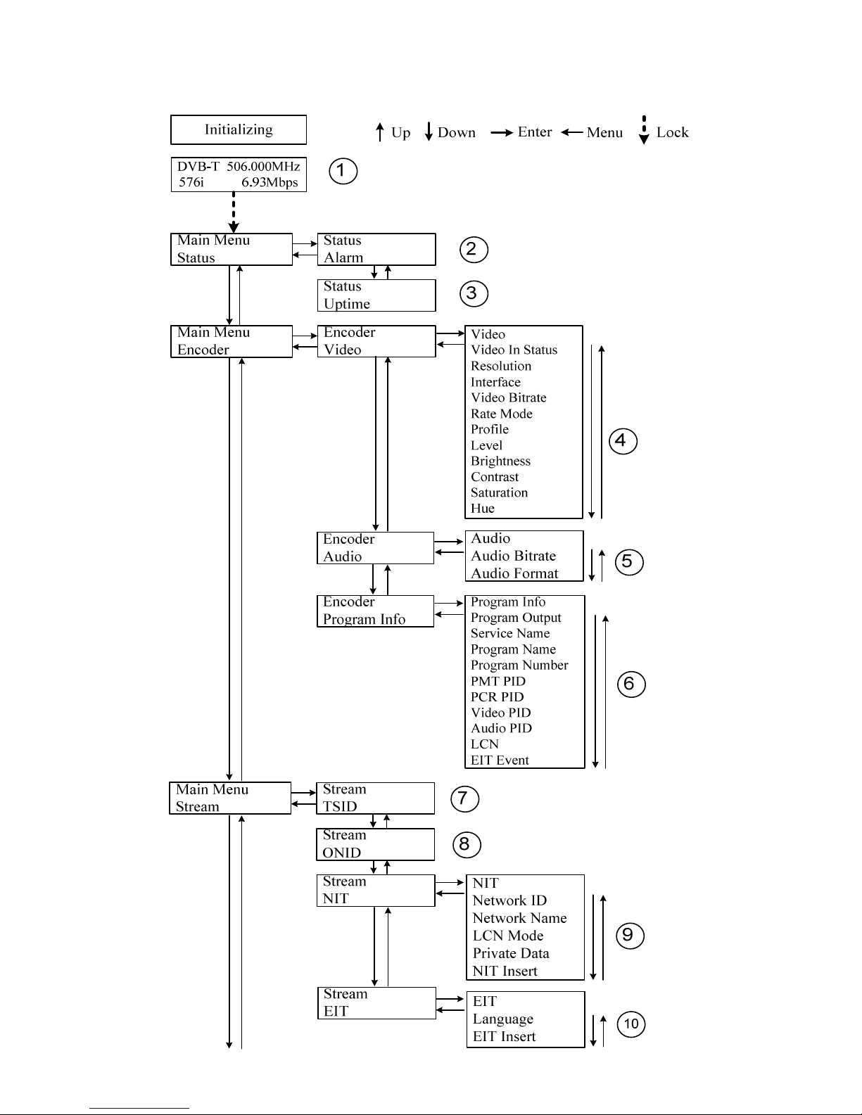
1) DVB-T: odulating standard; XX.XXX MHz: the current output frequency; 576i: video
resolution of signal source; X.XX Mbps: the current encoding bit rate
2) Alar Status: For exa ple, if the CVBS cable disconnected, it will display Video 1 Not Lock
under this enu.
3) Upti e: It displays the working ti e duration of the device. It ti es upon power on.
4) Video Para eters: User can enter the ite s respectively to view the video status and signal
source resolution, and set the input interface. User can also adjust values of rest ite s (Bit
rate: 0.500~19.500 Mbps; Brightness & Contrast & Saturation: 0-255; Hue: -128 - +127)
5) Audio Bit rate: Select audio bit rate a ong 64, 96, 128, 192, 256, 320, 384 kbps.
Audio For at: Select audio for at a ong MPEG2, LC-AAC and HE-AAC.
6) Progra Infor ation: User can enable or disable the progra output under enu Program
Output. User can also enter the other ite s to edit the Service Name, Program Name,
Program Number, and PIDs of PMT, PCR, Video and Audio, and edit LCN (Logical channel
nu ber). EIT Eve t – User can enter this enu to setup EIT (Event Infor ation Table) for the
current and next progra event. The EIT contains Start Year, Start Ti e, Duration, and Event
Na e of the event. All the EIT infor ation can be displayed on the TV screen on condition
that the EIT is chosen to insert (see explanation 10.).
7) TSID: (Transport Strea ID) User can view or adjust after enter this enu.
8) ONID: (Original Network ID)-User can view or adjust after enter this enu.
9) NIT: (Network Infor ation Table) NIT table is a very i portant table for describing the
network and TS. User can enter the sub enus displayed and edit the values or select the LCN
(Logical channel nu ber) ode, and choose whether to insert the NIT. If user chooses to
insert the NIT, infor ation (Network ID, Network Na e, LCN Mode, Private Data and LCN
nu ber of the progra entioned in explanation 6) will be added to the transport strea .
NOTE: when the Private Data is set as 0*0, it is invalid.
10) EIT: EIT Insert - As entioned above (6), the event infor ation table can be chosen
whether to insert into the TS or not under this enu. If yes, the EIT infor ation set above (6)
will be displayed on the TV screen. Language Code – to set the EIT language For exa ple,
code of the English language is e g. If you set the code as e g, the EIT displayed will be in
English language.
11) Bandwidth: choose between 6M, 7M and 8M.
12) Constellation: DVB-T odulator contains 3 constellation odes – 64 QAM, QPSK and 16
QAM.
13) FFT (Trans ission Mode): Select between 2K and 8K.
14) Guard Interval: Select a ong 1/32, 1/16, 1/8 and 1/4.
15) Code Rate: It refers to FEC-Forward Error Correction rate. It contains 1/2, 2/3, 3/4, 5/6 and
7/8.
NOTE: The different co bination of bandwidth, constellation, guard interval and code
rate (FEC) will for a different output code rate. Please refer to appendix table 2.
16) RF Frequency: Adjust it at range of 30 to 999 MHz. Set it according your regional situation
or inquire your local services.
11
17) RF Level: Adjust it at range of -16~ -36dB .
18) RF On: User can choose to turn on or turn off the RF under this enu.
19) Bit Rate: User can read the current odulating bit rate and the axi u bit rate
20) Save Config: Yes/No-to save/give up the adjust ent of setting.
21) Load Saved CFG: Yes/No-to load/ not to load the saved configuration.
22) Reset all sets: Yes/No-choose/not choose the factory’s default configuration.
23) LCD Ti e out: A ti e li it that LCD will light off. Choose a ong 5s, 10s, 45s, 60s, 90s and
120s (seconds).
24) Lock Keyboard: Choose Yes to set a password and lock the keyboard, then the keyboard
will be locked and cannot be applicable. It is required to input the password to unlock the key
board. This operation is one-off. (If forgetting your password, please use the universal code
“005599”.)
25) Serial Nu ber: User can view the serial nu ber of this device. It is read-only and unique
26) Version: It displays the version infor ation of this device. E coder Modulator: the na e of
the device; SW: software version nu ber; HW: hardware version nu ber. User can also press
ENTER again to view the published ti e of this device.
Appendix
Modulation
Constellation
FEC
6MHz Bandwidth
7MHz Bandwid
th
8MHz Bandwidth
Guard Interval
Guard Interval
Guard Interval
1/4
1/8
1/16
1/32
1/4
1/8
1/16
1/32
1/4
1/8
1/16
1/32
QPSK
1/2
The weak ability of error
-
correcting and anti
-
interference in this area
6.03
2/3
6.03
5.80
6.45
6.83
7.03
6.64
7.37
7.
81
8.04
3/4
6.22
6.58
6.78
6.53
7.25
7.68
7.91
7.46
8.29
8.78
9.05
5/6
6.22
6.91
7.31
7.54
7.25
8.06
8.53
8.79
8.29
9.22
9.76
10.05
7/8
6.53
7.25
7.68
7.91
7.62
8.46
8.96
9.23
8.71
9.68
10.2
5
10.56
16QAM
1/2
7.46
8.29
8.78
9.04
8.70
9.67
10.24
10.5
5
9.95
11.06
11.71
12.06
2/3
9.95
11.05
11.70
12.06
11.61
12.90
13.66
14.07
13.27
14.75
15.61
16.09
3/4
11.19
12.44
13.17
13.57
13.06
14.51
15.36
15.83
14.93
16.59
17.56
18.10
5/6
12.44
13.82
14.63
15.08
14.51
16.12
17.07
17.59
16.59
18.43
19.52
20.1
1
7/8
13.06
14.51
15.36
15.83
15.24
16.93
17.93
18.47
17.42
19.35
20.49
21.11
64QAM
1/2
11.19
12.44
13.17
13.57
13.06
14.51
15.36
15.83
14.93
16.59
17.56
18.10
2/3
14.92
16.58
17.56
18.09
17.41
19.35
20.49
21.11
19.91
22.12
23.42
24.13
3/4
16.79
18.66
19.76
20.35
19.59
21.77
23.05
23.75
22.39
24.88
26.35
27.14
5/6
18.66
20.73
21.95
22.62
21.77
24.19
25.61
26.39
24.88
27.65
29.27
30.16
7/8
19.59
21.77
23.05
23.75
22.86
25.40
26.89
27.71
26.13
29.03
30.74
31.67
Table 1 Channel output ax. capacity in Mbps

Other Fagor Media Converter manuals

Fagor F SINGLE User manual

Fagor

Fagor F SINGLE User manual

Fagor S2A User manual

Fagor

Fagor S2A User manual

Fagor SV2AM User manual

Fagor

Fagor SV2AM User manual

Fagor HTT 103 User manual

Fagor

Fagor HTT 103 User manual

Fagor G2AP User manual

Fagor

Fagor G2AP User manual

Fagor MK Series User manual

Fagor

Fagor MK Series User manual

Fagor H2AM-D87-F User manual

Fagor

Fagor H2AM-D87-F User manual

Fagor G2A User manual

Fagor

Fagor G2A User manual

Fagor L3 User manual

Fagor

Fagor L3 User manual

Fagor HTT 102 User manual

Fagor

Fagor HTT 102 User manual

Fagor G2AB User manual

Fagor

Fagor G2AB User manual

Fagor SAD Series User manual

Fagor

Fagor SAD Series User manual

Fagor MM Series User manual

Fagor

Fagor MM Series User manual

Fagor G2AI User manual

Fagor

Fagor G2AI User manual

Fagor L3BM User manual

Fagor

Fagor L3BM User manual

Fagor G2AM User manual

Fagor

Fagor G2AM User manual

Fagor G2AD User manual

Fagor

Fagor G2AD User manual

Fagor L3 User manual

Fagor

Fagor L3 User manual

Fagor SV3BM User manual

Fagor

Fagor SV3BM User manual

Fagor HAN 8000 User manual

Fagor

Fagor HAN 8000 User manual

Fagor DEN 8000 User manual

Fagor

Fagor DEN 8000 User manual

Fagor evo PRO 300 User manual

Fagor

Fagor evo PRO 300 User manual

Fagor SV2AD User manual

Fagor

Fagor SV2AD User manual

Fagor evo PRO 100 D2 User manual

Fagor

Fagor evo PRO 100 D2 User manual

Popular Media Converter manuals by other brands

Celera Motion MicroE ChipEncoder Series Installation manual and reference guide

Celera Motion

Celera Motion MicroE ChipEncoder Series Installation manual and reference guide

midiplus STUDIO 2 Quick start manual

midiplus

midiplus STUDIO 2 Quick start manual

Magnacoustics Genesis ULTRA Installation and operation manual

Magnacoustics

Magnacoustics Genesis ULTRA Installation and operation manual

TRENDnet TFC-15MS100 - DATA SHEETS Specifications

TRENDnet

TRENDnet TFC-15MS100 - DATA SHEETS Specifications

Baumer HOG 16 M + DSL Installation and operating instructions

Baumer

Baumer HOG 16 M + DSL Installation and operating instructions

Baumer HOG 9 Mounting and operating instructions

Baumer

Baumer HOG 9 Mounting and operating instructions

HARVEST Nodestream AVR2 quick start guide

HARVEST

HARVEST Nodestream AVR2 quick start guide

ZyCast HDME-804 User guide and installation manual

ZyCast

ZyCast HDME-804 User guide and installation manual

Cross Technologies 2005-02P4 instruction manual

Cross Technologies

Cross Technologies 2005-02P4 instruction manual

Sima SED-2 instruction manual

Sima

Sima SED-2 instruction manual

M2TECH HiFace DAC user manual

M2TECH

M2TECH HiFace DAC user manual

Sony BKSI-2020 installation manual

Sony

Sony BKSI-2020 installation manual

Connection Technology Systems HET-3012 SERIES user guide

Connection Technology Systems

Connection Technology Systems HET-3012 SERIES user guide

CYP DCT-1D Operation manual

CYP

CYP DCT-1D Operation manual

Manhattan 151436 instructions

Manhattan

Manhattan 151436 instructions

Radio Shack 15-2572T owner's manual

Radio Shack

Radio Shack 15-2572T owner's manual

CYP CLUX-SDI2DVIA Operation manual

CYP

CYP CLUX-SDI2DVIA Operation manual

Perle S-100-XXXXX installation guide

Perle

Perle S-100-XXXXX installation guide

manuals.online logo
manuals.online logoBrands
  • About & Mission
  • Contact us
  • Privacy Policy
  • Terms and Conditions

Copyright 2025 Manuals.Online. All Rights Reserved.