8
fagorindustrial.com
The unit should not be installed under ambient temperatures higher than 100 °F.
If the relative humidity is higher than 60 %, the door frames may sweat water. This
is not a malfunctioning of the unit.
2.6 Connections
Refer to the amperage data in this manual or on data plate and your local code
or the National Electrical Code to be sure unit is connected to the proper power
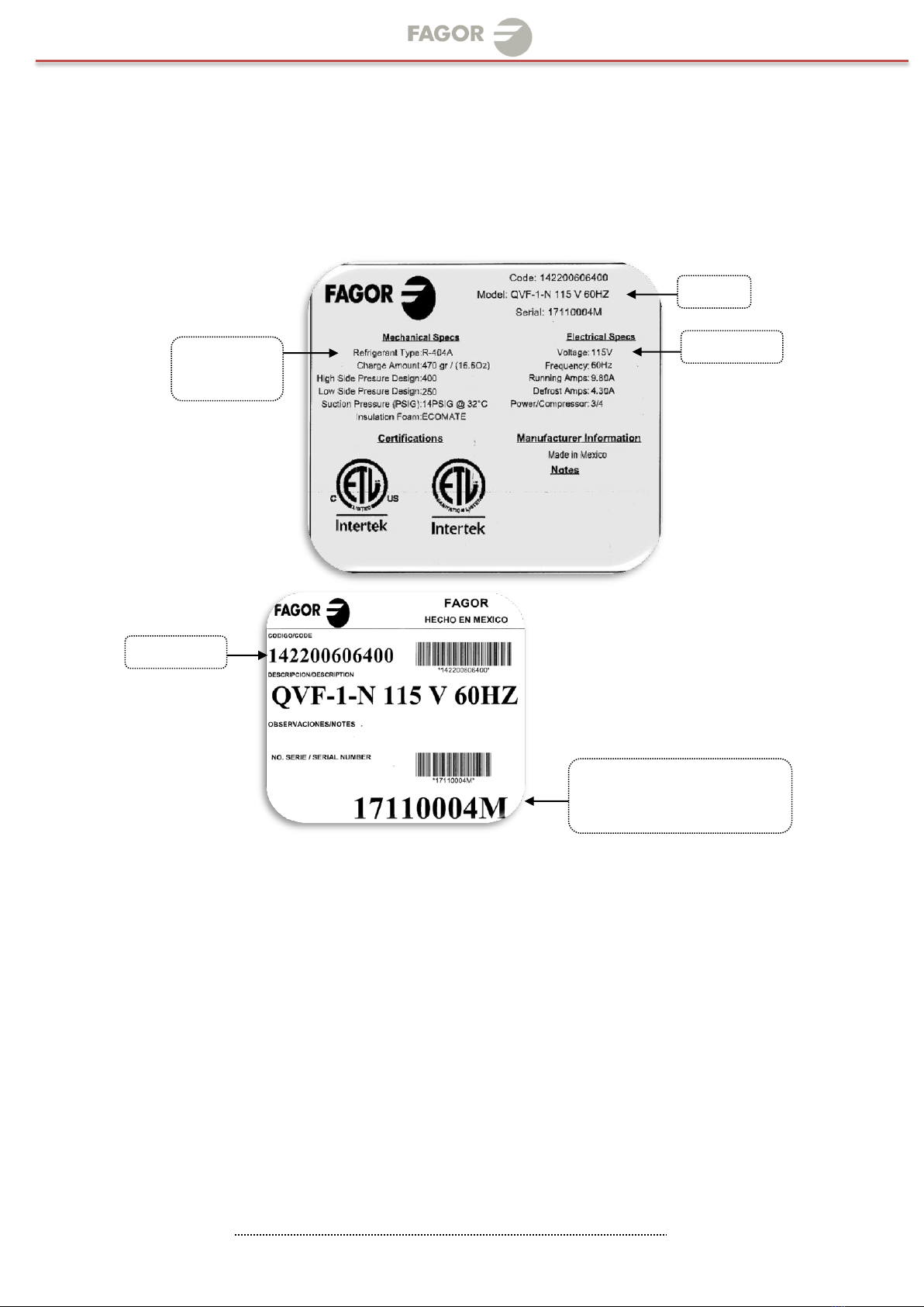
source. Verify correct incoming voltage according to the Data Plate information.
The data plate in located inside the unit, near the top front left corner. Under
any circumstances should the data plate be removed from the unit.
The data plate is essential to identify the particular features of your unit and is
of great benefit to installers, operators and maintenance personnel. It is
recommended that, in the event the data plate is removed, you copy down the
essential information in this manual for reference before installation.
A protected circuit of the correct voltage and amperage must be run for
connection of the supply cord. Unit must be grounded and connected in
accordance with NEC Article 422 Appliances.
OPERATION
3.1 General information.
3.2 Control panel description.
3.3 Machine settings and programs.
3.1 General information
Good air flow inside the cabinet is critical. Do not block air flow to the fans.
Allow three inches of space along the front, back, and sides.
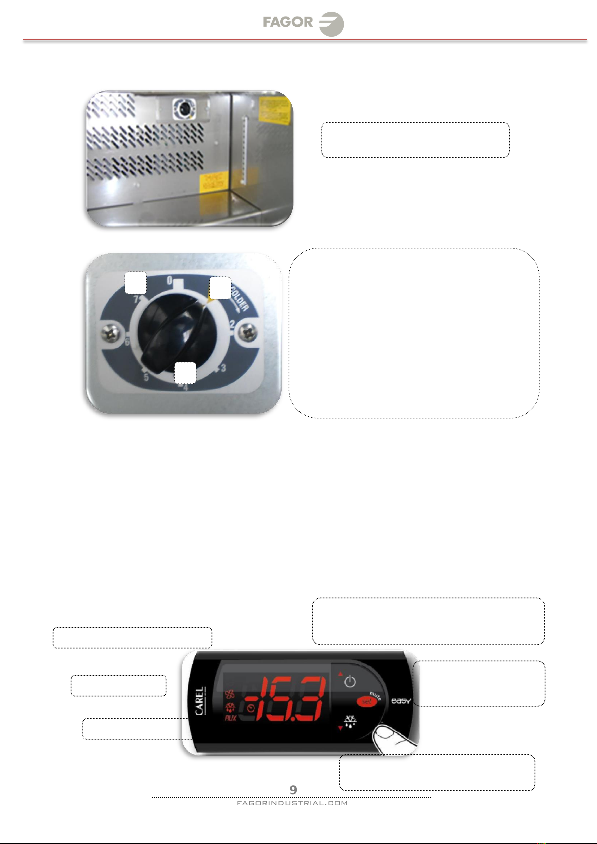
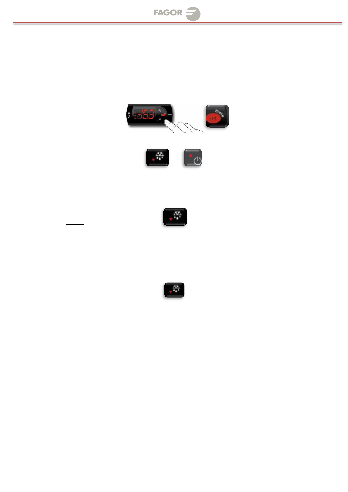
3.2 Control panel description
3.2.1 Analog Thermostat
ONLY REFRIGERATOR MODELS (Example: FMT_FST_FUR)
Before you connect the unit to the power supply, verify the thermostat is
NOT in the OFF position (the position of the thermostat must be different
than zero).If the thermostat is in the OFF position, the compressor will not
run. Keep in mind, the evaporator fan sand lights will still have power while
the thermostat is in the OFF position.
The knob of the thermostat is the temperature controller. This is located
inside the cabinet. Please be sure that the knob of thermostat is pointing to
the yellow arrow (Figure # 3, See p. iv).This position is recommended by the
factory to assure correct function of the equipment ( Figure #1 See p. iv).
Note:Keep in mind, if you move the knob to a different position that is
recommend from factory, these temperature will change, as well.
The knob position near the number one, gives you the warmest temperature
and the knob position near the number seven, gives you the coldest
temperature.