F&F FW-GS-230-B User manual

F&F Filipowski sp. j.
Konstantynowska 79/81, 95-200 Pabianice, Poland
phone/fax (+48 42) 215 23 83 / (+48 42) 227 09 71
www.fif.com.pl; e-mail: biuro@fif.com.pl
Do not dispose of this device to thrash with other unsorted waste! In accordan-
ce with the Waste Electrical and Electronic Equipment Act any household electro-wa-
ste can be turned in free of charge and in any quanty to a collecon point established
for this purpose, as well as to the store in the event of purchasing new equipment (as
per the old for new rule, regardless of brand). Electro-waste thrown in the trash or aban-
doned in the bosom of nature pose a threat to the environment and human health.
Wireless system
- 1 -
Description of the system
F&Wave is a family of wireless devices controlled by radio with a range of up to 100
meters*. The receivers are available in either a DIN-rail mounting version (housing 1S)
or a Ø60 flush-mounted version. The transmitters are available as handheld remo-
te controllers or as a flush-mounted version. The receivers relay control signals. The
device that receives a control signal from the transmitter will automatically send it
forward, which allows to increase the range of the remote control.
* Range of up to 100 meters in open space without any interfering factors. In building conditions and in the presence of
interference sources (power lines, transmitters, etc.) the actual range may be smaller.
FW-GS-230-B
Radio glass button
4-fields

- 2 -
4-button remote control transmitter with 230V mains power supply;
Cooperation with remote control receivers of the F&Wave system;
The ability to control any number of receivers;
Functionality depending on the receivers used – bistable (also with a dimmer),
monostable, timed, always on, always off;
The configuration of the S2 button field can be changed to ON – always switch on
paired receivers and/or raise the roller blinds;
The configuration of the S4 button field can be changed to OFF – always switch off
paired receivers and/or lower the roller blinds;
A contactless feature that illuminates the touch fields of the buttons when the
hand is in close physical proximity;
Button operation indicators;
The ability to set levels of backlight brightness;
Easy to install in the �60 flush-mounted box, thanks to a dedicated mounting
element;
Low power consumption – low operating cost.
Installation of the device should be carried out by a qualified installer
after reading this manual. Make sure that the connection cables are not
live before starting the installation work. The method of storage, trans-
port, and operation influences the proper operation of the device.
Module features
Description of the device

- 3 -
Connection
L – power supply L
N – power supply N
Do not touch the back of the unit
when the power is switched on.
The configuration of the S2 touch field can be changed to ON and the
configuration of the S4 touch field to OFF. To do this, select the ap-
propriate mode according to the attached table using the knob located
on the housing of the module.
Mode Input
A S1 S2 S3 S4
B S1 ON S3 S4
C S1 S2 S3 OFF
D S1 ON S3 OFF
Due to the nature of transmission and retransmission, do not use the
same button in the transmitter more often than every 2 seconds. The
switchover of the receiver may take place with a short delay.
Button configuration
It is not recommended to use remote bistable transmitters to control a
group of receivers because of the risk of desynchronization of the swit-
ch-on status (especially in the case of operation at longer distances and/
or simultaneous use of local buttons on receivers).

- 4 -
Refer to the user manual of the receiver for a detailed description of pairing and
unpairing of the buttons with the receiver.
The following is an example of how to handle receivers: FW-R1, FW-R2, FW-
-STR1, FW-LED2, FW-D1.
Pairing
Once the receiver is correctly connected, press and hold
the PROG button until the device switches on the output
circuit and the communication LED goes out.
Tap the desired touch field.
②
①
③A proper pairing will be confirmed by switching off the output circuit tem-
porarily and turning the LED on again.
Exiting the programming mode of the receiver is automatic after 30 se-
conds of waiting for the signal from the transmitter or after short pressing
the PROG button.
Unpairing
Unpairing the flush-mounted transmitter from the receiver is only possible by clearing
the list of all transmitters in the receiver. To clear the list of transmitters connected to
the receiver, press the PROG button and keep it pressed for a minimum of 10 seconds.
Rapid blinking of the communication diode will indicate that the controller memory
has been cleared.

- 5 -
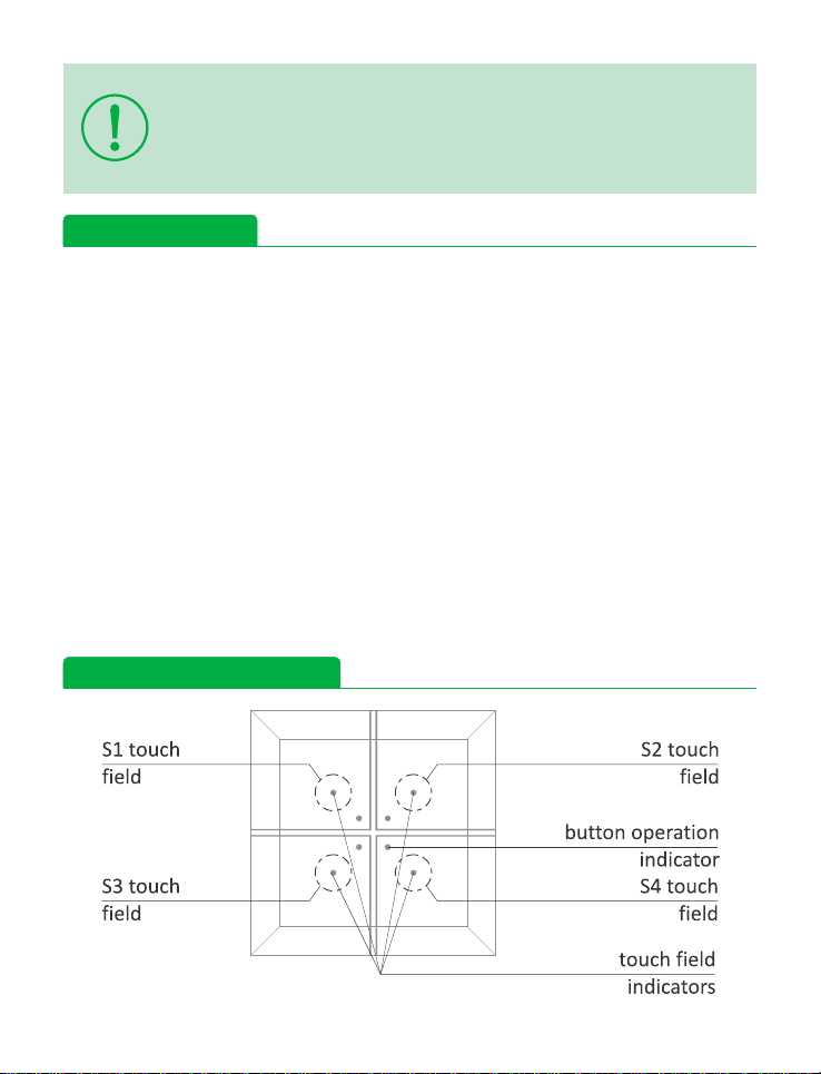
Personalization of button operation
The FW-GS4 Glass Buttons allow you to set the brightness level of the indicators in the
active state in the range of 50÷100% and in the inactive state in the range of O÷30%.
To set the brightness of the indicators:
Move your finger to the middle of the button and hold it for 10 seconds witho-
ut activating any of the touch fields - during this operation, the white indica-
tors of all fields will be on.
Entering the personalization mode will be confirmed by the blinking of the
orange indicator on the touch field No. 1.
Using the touch fields No. 3 and 4, set the brightness of the indicators in the
inactive state. The set brightness is continuously displayed by white indicators.
In order to confirm the brightness level in the inactive state, press touch field
No. 1 (the one with blinking orange indicator), after which the orange indicator
in field No. 2 will start to blink to indicate the active personalization mode in
the active state.
Using the touch fields No. 3 and 4, set the brightness of the indicators in the
active state. The set brightness is continuously displayed by white indicators.
In order to confirm the brightness level in the active state, press touch field
No. 2 (the one with blinking orange indicator), after which all indicators will
be switched off.
Lack of any user action for 10 seconds will result in exiting the personalization
mode while keeping the introduced changes.
①
②
③
④
⑤
⑥
⑦

- 6 -
Transmitters Receivers Ø60 box DIN rail
flush-mounted
FW-RC4-AC, FW-RC5
Single relay FW-R1P
FW-R1P-P
FW-R1D
FW-R1D-P
remote controls
FW-RC4, FW-RC10, FW-KEY4
Double relay FW-R2P
FW-R2P-P
FW-R2D
FW-R2D-P
wall buttons
FW-WS1, FW-WS2, FW-WS3
Universal dimmer FW-D1P FW-D1D
glass buttons
FW-GS-230-B, FW-GS-230-W,
FW-GS-24-B, FW-GS-24-W
Roller blind controller FW-STR1P
FW-STR1P-P
FW-STR1D
FW-STR1D-P
Dual-channel LED controller FW-LED2P FW-LED2D
F&Wave system device
Technical data
power supply 80÷265 V AC/DC
power consumption
button pressed 0.5 W
standby 0.25 W
radio frequency 868 MHz
working temperature -25÷65°C
terminal 2.5 mm² screw terminals
tightening torque (max) 0.4 Nm
mounting Ø60 flush-mounted box
dimensions 81×81×12 mm
protection level IP20

- 7 -FW181029
Compliance with standards
RED 2014/53/EU
PN-EN 55024, PN-EN 60669-1, PN-EN 60669-2-2, PN-EN 62368-1,
PN-ETSI EN 300 220-1, PN-ETSI EN 300 220-2,
PN-ETSI EN 301 489-1, PN-ETSI EN 301 489-3.
CE declaration of conformity is available for download at:
www.fif.com.pl.
Warranty
F&F products are covered by a 24 month warranty from the date of purchase.
The warranty is effective only with a proof of purchase.
Contact your dealer or directly with us.
For more information on the procedure for submitting a warranty claim visit our
webpage: www.fif.com.pl/reklamacje

Table of contents
Other F&F Transmitter manuals
Popular Transmitter manuals by other brands

M-system
M-system 10VS instruction manual

Lectrosonics
Lectrosonics DBu-LEMO instruction manual

Indexa
Indexa DF-100 operating instructions

Omega Engineering
Omega Engineering CYTX231 Series user guide

Becker
Becker Centronic MemoControl MC511 Assembly and operating instructions

FrSky
FrSky DHT-U instruction manual