manuals.online logo
Brands
  1. Home
  2. •
  3. Brands
  4. •
  5. Jamara
  6. •
  7. Transmitter
  8. •
  9. Jamara CCX Pro User manual

Jamara CCX Pro User manual

ES - Instrucción
GB - Instruction
CCX Pro 2,4 GHz
Emisora | Transmitter
No. 061200
44/20
ES - Información general
JAMARA K. no se hace responsable de los daños causados al producto en sí o por medio de
esto, a menos que esto se debe al mal funcionamiento o errores de manejo. El cliente solo tiene la
responsabilidad completa para el uso y manejo adecuado, incluyendo, sin limitaciones, el montaje,
el proceso de carga, el uso de hasta la elección de la zona de aplicación. Por favor, consulte las
instrucciones de uso y funcionamiento, contiene información y avisos importantes.
GB - General information
JAMARA e.K. is not liable for any damage caused to the product itself or by it, if this is due to impro-
per operation or handling errors. The customer alone bears the full responsibility for the proper use
and handling, including in particular, assembling, charging and using the model, and selecting the
area in which to use it. Please refer to the operating and user instructions, which contain important
information and warnings.
ES - Declaración de conformidad
Por la presente JAMARA e.K. declara que el producto “CCX Pro 2,4 GHz,
No. 061200“ cumplen con las Directivas 2014/53/UE, 2011/65/UE.
El texto completo de la declaración de conformidad de la UE está disponible en la
siguiente dirección de Internet: www.jamara-shop.com/Conformity
GB - Certicate of Conformity
Hereby JAMARA e.K. declares that the product “CCX Pro 2,4 GHz, No. 061200“ complies with
Directive 2014/53/EU, 2011/65/EU.
The full text of the EU Declaration of Conformity is available at the following Internet address:www.
jamara-shop.com/Conformity
Contenido del kit
• Emisora
• Receptor
• Instrucciones
Accesorios requeridos
8 x pilas AA Ref. 140267 (4 Uds.))
Esta emisora ja nuevos estándares en el área de RC-Car. Se ha adoptado la mejor técnica
de la frecuencia a 2,4 GHz basado en nuestra CCX . Esta emisora cuenta con una pantalla
grande y de fácil programación.
Características:
• 3 Canales Totalmente programable
• Sistema de 2,4GHz
• Dual Rate
• Inverso Servo
• Ajustable Servo Central y desviaciones de Servo nal
• Resolución de 1024
• 100 mW frecuencia hopper
• Memorias para 10 modelos
• Expo curva ajustable
• ABS función en 3 pasos ajustable
• Programación a través de Jog/Dial Rad
• Indicador de voltaje con señales acústicas de baja tensión
• Compatibles con los receptores existentes CCX
• Toma de carga
• Jack de 3,5mm para conectar Simulador
• Dimensiones 159 x 127 x 196 mm
• Peso de 405 g
• Porgramable receptor a Fail-Safe
• Display: 100 x 35 mm
Datos técnicos:
Banda 2,4 GHz
Tipo de modulación AFHDS
Tensión de trabajo 4,8- 7,4 V DC
Resolución de los servos 10 Bit (1024 niveles)
Dimensiones 37 x 22 x 13 mm
Peso 7,6 g
Box contents:
• Transmitter
• Receiver
• Instruction
Recommended Accessories
8 x AA Batteries Ord. No. 140267 (4 pieces)
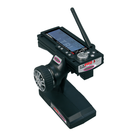
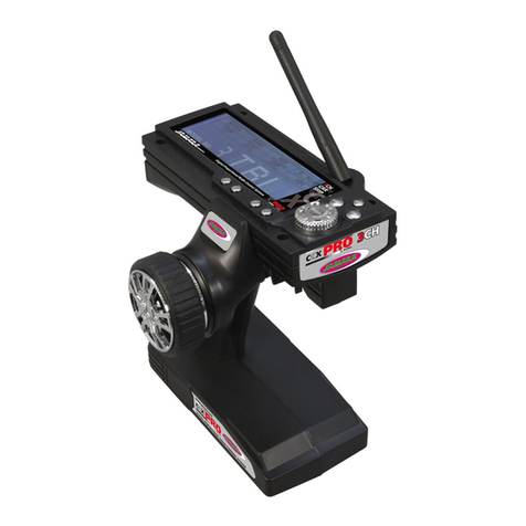
This transmitter sets new standards in the RC-Car area. The established 2.4 GHz technology from
our CCX car radio was adopted into the CCX Pro. A huge display and easy programming complete
this transmitter.
Features:
• 3ch fully programmable
• 2,4GHz System
• Dual Rate
• Servo reverse
• Adjustment of servo centre and travel
• 1024 display resolution
• 100mW Frequency hopper
• 10 model memory
• Adjustable Expo
• 3 stage ABS setting
• Programming by Jog/Dial wheel
• Display backlight
• Voltage indicator with audible low voltage warning
• Compatible with CCX receivers
• Charging socket
• 3,5mm jack and simulator connection
• Weight 405 g
• Dimensions 159 x 127 x 196 mm
• Programmable Fail Safe on receiver
• Display: 100 x 35 mm
Technical data:
Frequency 2,4 GHz
Modulation AFHDS
Operating voltage 4,8 - 7,4 V DC
Servo resolution 10 Bit (1024 steps)
Dimensions 37 x 22 x 13 mm
Weight 7,6 g
Este modelo no es ningún juguete!
Lea atentamente la instruccion completa y seguridad antes de poner el modelo
en funcionamiento
Atención! Leer completamente las notas de advertencia / instrucciones de
seguridad estos son para su seguridad y puede evitar accidentes / lesiones.
For model building only - Not a toy!
Read the complete instructions and security instructions carefully before using the
model.
Caution! Please fully and carefully read warnings/ safety instructions.
These are for our own security and can avoid accidents/injuries.
Tenga también en cuenta la siguiente información:
• Antes de empezar, asegúrese de que la estación modelo está apagada.
• Asegúrese de que la emisora y el receptor funcionan correctamente, que el bindign esta correcto.
• Encienda siempre primero la emisora y luego el receptor.
• Siempre apague primero el receptor y luego la emisora.
• Realice una prueba de alcance y funcionamiento antes de comenzar.
• No poner en peligro a animales y personas.
• Sólo poner en marcha el modelo en lugares apropiados.
• No usar la emisora y el modelo cuando llueva, haya rayos, truenos y ni en el agua.
• Cuando no for utilizados ni la emissora y ni el modelo, retirar las pilas.
Following should be strictly adhered to:
• Before Switching on the system ensure that throttle stick is in the off position.
• Check that the transmitter and receiver are compatible and bonded to one another.
• Always switch the transmitter on  rst and then the receiver.
• Always switch the receiver off  rst and then the transmitter .
• Complete a full range and function test before every take-off .
• Never over- y people and do not allow your model to endanger people or animals.
• Do not  y near to over-head cables, buildings or air elds.
• The system must not be operated in rain, or thunder storms.
• If you do not intend to use the transmitter for a long period, remove the batteries.
Frequency bands: 2.4GHz Frequency range: 2405,5 – 2475,0 MHz EIRP: < 30 mW (max. power transmitted)
2
ES - Dispositivos para la carga
Cuando se usa un cargador NiCd o NiMH en la emisora, asegúrese que las células estén com-
pletamente cargadas, la tiene que volver a recargalas nuevamente después de cada uso. Preste
atención a que está utilizando el número recomendado de células.
Asegúrese de poner un cargador adecuado, por ejemplo ref.150004, usted debe consultar a su
distribuidor. Después de las baterías están totalmente cargadas,desconecte la emisora, a la toma
de carga del sistema de recepción y quitar el cargador de la toma.
Retire las pilas en la emisora y el modelo, si usted no lo usa durante un periodo prolongado.
Carga la batería de la emisora, siga estos pasos:
1. Inserte las pilas con la poridad correcta.
2. Enchufe el cargador en un tomacorriente de pared
3. Enchufe el cargador en la toma de carga de la emisora.
4. Retire el cargador del enchufe y desenchufe el cargador una vez
que las baterías están totalmente cargadas.
¡Atención!
Durante la carga, al abrir el compartimiento de la batería.
GB - Charging The Batteries
If you use NiCad or NiHm rechargeable cells for your transmitter ensure that the cells are fully
charged before using the system. Please be aware that due to the self-discharge characteristics of
this type of cells that they should always be fully charged prior to use. Please refer to the battery
manufacturers recommendations regarding charging current etc.
Use only a high quality charger which is suitable for this type of cells such as our item 15 0004.
For further information please contact your local dealer. Once charging is complete, always discon-
nect the batteries from the charger and unplug the charger from the mains supply.
Remove the batteries from the model and transmitter if you do not intend to operate it for a
longer period of time. To charge teh transmitter batteries please proceed as follows:
1. Fit the batteries observing the correct polarity.
2. Plug the charger into the household mains.
3. Connect the charging cable to the transmitter.
4. Remove the charging cable and unplug the charger as soon as the batteries are full.
Warning!
Remove the battery hatch cover whilst charging!
1
2
3
4
5
6
8
9
A
7
Vista lateral derecha
1. Antena 2,4GHz
2. Volante
3. 3 Canales
4. Batería/Compartimiento de la batería
5. Canal 1 Dual Rate
6. Canal 3 Trim
Vista trasera
7. On/Off
Vista lateral izquierda
8. Conexión para el cable del simulador
9. Toma de carga
A. Acelerador
Right - side view
1. 2,4 GHz Antenna
2. Steering Wheel
3. 3 channel
4. Battery Hatch
5. Dual Rate channel 1
6. Trim channel 3
Rear View
7. ON/OFF Switch
Left - side view
8. Connection for
simulator cable
9. Charging socket
A. Throttle Lever
Programación
B. Pantalla LCD
C. Volver
D. Clave de enlace
E. Fin/ Selección de menú
F. Conrmación ( derecha/izquierda)
G. Trim canal 2 detrás
H. Trim canal 2 delante
I. Trim canal 1 izquierda
J. Trim canal 1 derecha
Programming Panel
B. LCD display
C. Back
D. Binding Button
E. Selection for sub-menu
F. Conrmation ( right / left)
G. Trim channel 2 back
H. Trim channel 2 front
I. Trim channel 1 left
J. Trim channel 1 right
Display
Mediante un acuerdo razonable de botones, teclas y pantalla LCD, la emisora CCX Pro 2,4GHz
puede ser programada forma rápida y sencilla. Todos los canales se pueden recortar, también llevó
a invertir
la dirección. Además, hay funcciones disponible como Dual-Rate, La EXPO y ABS.
Display
Thanks to the logical and well thought out lay-out of the Programming Panel and the positioning of
the switches and LEDs the CCX Pro 2,4 GHz transmitter can be quickly and simply programmed. All
channels can be trimmed and the direction changed.
Furthermore the transmitter is equipped with a Dual Rate, a EXPO- and ABS-Function.
B
C
D
E
F
G
H
I
J
33
DE - Instalación del receptor GB - Connecting To The Receiver
Regulador
ESC
Interruptor
Switch
Interruptor
Switch
Servo de dirección
Steering Servo
Servo de dirección
Steering Servo
Servo gas
Throttle Servo
Receptor
Receiver
Receptor
Receiver
Batería
Receiver Battery
Canal 2
Channel 2
Canal 1
Channel 1
Modelo con un motor elektrico
Wiring Diagram For Electric Models
Modelo con un motor de combustión-
Wiring Diagram for I/C Engine Models
Batería
Battery Pack
Motor
Motor
DE - Antena
Ajuste la antena vertical de 2,4GHz, como se muestra en la imagen. Usted no puede, conectar la
antena a los objetos metálicos, porque la gama disminuirá.
GB - Antenna
Mount the 2.4 GHz antenna vertically as shown in the diagram.
Do not allow any metal object to come into contact with the antenna or to shield it as this will reduce
the range.
2,4 GHz
Antena
2,4 GHz
Antenna
Receptor
Receiver
4
ES - Enlace de la emisora con el receptor
En un moderno sistema de 2,4GHz, es imprescindible que la emisora y el receptor están unidos en
el modelo. El receptor acepta sólo los signales de su emisora.
Una vez que se no realiza el enlace, por favor, haga lo siguinte:
A. Coloque la batería cargada en la emisora o pilas nuevas. Deje la emisora desenchufada.
B. Coloque el cable de conexión de los tres canales.
C. Encender la emisora, mientras haces el bindingde la batería con el receptor. Depende de la
versión del software, señala su receptor varios modo de binding (en vez de parpadear, la LED
brilla o esta apagado). El binding es siempre lo mismo en todas las versiones. La LED en el
receptor impieza a parpadear y indica que el receptor no esta en el modo binding.
D. Pulse el botón de encendido de la estación y, al mismo tiempo cambiar el canal.
E. La emisora impieza a parpadear y indica que estas en el modo binding.
F. Quitar el dedo el botón de encendido de la emisora y retirar del enchufe del receptor.
G. Quitar el dedo el botón de encendido de la emisora y retirar del enchufe del receptor.
H. Cuando haga la instalación, tratar de hacer todo correctamente.
La siguiente gura muestra grácamente el proceso de unión e identica los elementos que deben
ser.
GB - Binding
As with all modern 2.4GHz R/C systems the receiver must be bound to the transmitter to ensure that
the receiver will only react to signals from that transmitter.
If you wish to re-bind the receiver with the transmitter please proceed
as follows:
A. Ensure that the transmitter is  tted with fresh or fully charged
batteries and leave the transmitter off.
B. Plug the binding plug (included) into the channel 3 socket on the
receiver.
C. Switch the receiver system on by connecting the battery.
The receiver LED will begin to  ash indicating that the receiver is in
bonding mode.
D. Press and hold down the binding button on the transmitter while
switching it on.
E. Watch the receiver LED and once it stops blinking the binding
process is copmlete.
This process may take up to 5 seconds.
F. Release the binding button on the transmitter and disconnect the
binding plug from the receiver. Set the receiver and transmitter.
G. Install all of the components correctly and carefully check that
everything is operating correctly.
H. If the receiver fails to bond or does not function after bonding
repeat the above procedure until a successful bonding is achieved.
La programación de FailSafe.
1. Desprición de la función
El entegrado FailSafe se debe principalmente para el uso de barcos y vehículos. Se utiliza para
evitar lo daño. Si el receptor pierde la señal del transmisor, o devuelve el control de la velocidad del
servo del canal de gas de forma automática a la posición predeterminada.
2. Ajuste
a. Acienda la emisora
b. Acienda el receptor. La siñal LED parpadea continuamente, lo que indi ca que el receptor está
listo.
c. Mover la palanca del acelerador en la emisora en el freno o la toma su posición de los Servos
o regulador de velocidad. Sujete
la palanca del acelerador a esta posición.
d. Pulse el botón de conguración en el receptor. La señal LED parpadea durante 3 segundos
(ver a la izquierda).
e. Se guarda la conguración y se puede poner el acelerador en la posición neutra.
3. Test la conguración
a. Acienda la emisora.
b. Acienda el receptor.
C. Desconecte la emisora.
d. El receptor se pierde la señal y impulsa el Servo por ejemplo:
el variador de velocidad en el canal de acelerador a la posición previamente programada.
e. Siga los pasos anteriores, la función FailSafe funcionará correctamente.
Programming of the integrated FailSafe unit.
1. Function Description
The built-in FailSafe unit is mainly for the use on boats and cars. It is used to prevent loss of the
model in case of signal loss and returns the servo to the position which was set before.
2. Setting
a. Turn on the transmitter
b. Turn on the receiver. The signal LED will ash continuously and
indicates that the receiver is ready.
c. Move the throttle lever on the transmitter in the braking or outlet position.
Hold the throttle lever in this position.
d. Press the Setup button on the receiver. The signal LED ashes for 3 seconds (see left).
e. The setting is saved and you can bring back the throttle into neutral position.
3. Testing the settings
a. Turn on the transmitter.
b. Turn on the receiver.
c. Turn off the transmitter.
d. The receiver will now lose the signal and drives the servo or the
speed control on the gas channel to the previously programmed
position.
e. If these steps work, you have set the FailSafe.
LED
LED
Clave de enlace
Binding Button
Clave de enlace
Binding Button
Conexión de enchufe
Binding Plug
Receptor
Receiver
Receptor
Receiver
Batería
Battery
Batería
Battery
Fail Safe
LED
5
ES - Secuencia de la conexión
1. Recoger los elementos
2. Gire el canal
3. Conecte el cargador al receptor del canal
4. Compruebe que el LED de la estación y el receptor están conectados con la luz.
5. Si el sistema se enciende, ya se puede utilizar
GB - Switching On
1. Plug in all of the components.
2. Switch the transmitter on.
3. Connect the receiver battery to the receiver.
4. Check that the LEDs on both the transmitter and the receiver illuminate solidly.
5. The system is now correctly switch on and operating and can now safely be used.
ES - Secuencia de desconectar la unidad
1. Apague primeramente el cargador.
2. Apague la emisora
GB - Switching Off
1. Disconnect the receiver battery
2. Switch off the transmitter
2. Encender el receptor
2. Switch the
receiver on
1. Encender la emisora
1. Switch the
transmitter on
Encender
Switching on
2. Apagar la
emisora
2. Switch off
the transmitter
1. Apagar el
receptor
1. Switch off
the receiver
Apagar
Switching Off
6
ES - Funciones de las teclas
Enter: Gire la perilla para seleccionar el menú
Enter: Pulse el botón para seleccionar el elemento de menú.
End: Pulse para seleccionar un submenú
Back: Pulse para salir del menú
GB - Button functions
Enter: Turn the knob to navigate through the menu
Enter: Press the button for menu select
End: Press to select a submenu
Back: Press to exit the menu
Pantalla LCD
La emisora se enciende, la pantalla muestra la tensión en voltios y el número (Nr°8 aqui) y el nobre
( en este caso ABC) del modelo. Al girar la tecla Intro para cambiar entre tensión y modelo.
Si el voltaje cae por debajo de 9,5V, le indicará la pantalla.
Si la tensión continúa bajando, el mensaje de advertencia „LOW POWER“ (de baja potencia!) y
suena un tono de advertencia.
LCD Display
The transmitter is turned on, the display shows the voltage in volts and the number (here 8) and the
name (in this case ACB) of the model.
By turning the Enter key you can switch between voltage and model.
If the voltage drops below 9.5V, this is indicated on the display.
If the voltage continues to drop, the warning message „Low Power!“ will light up and a buzzer will
sound.
MODEL
En la emisora puede hasta 10 modelos ajustar individualmente en la memoria.
La emisora muestra la conguración en „Nr. 0“ y FSO. En la imagen al lado muestra espacio de
memoria“ Nr.8 y el modelo de nobre „ACB“.
Encienda la emisora y pulse „Enter“.
Al gira el botón Enter entrará en el Menú „Modell“ para izquierda o derecha para seleccionar el mo-
delo. Pulse para conrmar el modelo de la tecla „Enter“. Para salir del menú, pulse el botón „Back“.
MODEL
You can store up to 10 models in the transmitter.
Each memory can be set individually for each model.
The default setting of the transmitter shows „no. 0 „FS0“.
In the picture you see the space „no. 8“ and the model name
„ACB“.
Switch the transmitter on and press „Enter“.
By turning the enter button in the menu „Model“ to the left or right, you can choose the model of your
choice. Press the Enter button to conrm the model.
To exit the menu, press „BACK“.
7
ES - NAME
En este menú se puede asignar a cada modelo un nombre (máximo 3 caracteres)
„ Modelo No.“ = Número del modelo
„ ACB“ = Símbolo
Pulse „Enter“ . Para seleccionar la opción „Name“ (nombre) gira el botón Enter. La primera letra(
neste caso A) comienza a parpadear. Al girar el botón „Enter“ para seleccionar una letra. Pulse el
botón „End“ para pasar a la siguiente letra. Repita el proceso para la tercera letra. Si ha introducido
el código, conrme pulsando la tecla „Enter“ Para salir del menú, pulse el botón „Back“
GB - NAME
In this menu you can assign a name to each model (max. 3 characters).
„Model No.“ = model number
„ACB“ = shortcut
Press „Enter“. To select the option „Name“ turn the enter button. The rst letter (here A) starts to
ash. By turning the Enter button you can select a letter. Press the „End“ key to switch to the next
letter. Repeat the process for the third letter. Once you have entered your code, conrm by pressing
the „Enter“ key.
To exit the menu, press „BACK“.
Servoinversión
Channel: Número de canal 1.3
REV: Servoinversión
NOR: Servo de dirección normalhtung
Pulse „Enter“. Girar el botón para el canal deseada. Pulse ‚END“
para pelear el ajuste. El ajuste está destellando, ahora seleccione el
botón „REV“ o „NOR“ y pulse Enter.
Servo reverse direction
Channel: Channel number 1 to 3.
REV: Reverse servo direction
NOR: Normal servo direction
Press „Enter“. Turn the knob to get to the desired channel. Press „END“ to change the setting. The
setting is ashing, now select the button „REV“ or „NOR“ and press Enter.
E POINT
Esta palma puede denir permite a la dirección de sus servos. Si el servo de dirección a escala
completa (a la izquierda oa la derecha) son diferentes, puede ajustar esta conguración.
Valor de salida es de 100%.
Desplazamientos de 0 a 120%.
Pulse „Enter“ y Seleccione „E POINT“en el menú. Para seleccionar la dirección servo, pulse el canal
(1,2 o 3) en la dirección deseada ( 1=
Volante, 2= palanca del acelerador, 3= tercero botón de canal). Pulse el botón „END“ para llegar
el n de la conguración. Gira el botón para jar el valor y pulse „ENTER“ para conrmar el valor.
E POINT
With this setting you can set the steering angle of your servos. If your steering servo differs at full
scale (left or right) differ, you can adjust it with this setting.
Output value is 100%.
Displacements from 0 to 120%
Press „Enter“ and select „E POINT“ in the menu. To select the servo direction, press the channel
(1, 2 or 3) ind the desired direction (1 = wheel, 2 = throttle, 3 = third channel key). Press „END“
to enter the setting of the channel. Select with the rotary knob to set the value and press Enter to
conrm the value.
TRIM
Con esta conguración se puede establecer la posición neutral de los servos.
Valor de salida es de N00.
Desplazamientos de L30 sob N00 hasta F30 sob N00 hasta B30
L = Izquierda; N= Posición Cero; R= Derecha; F= Delante; B= Volver.
Pulse „ENTER“ y selecciona „TRIM“ en menú. El canal parpadear. Pulse „END“ para obtener el
ajuste de la canal. Con la perilla de ajuste para seleccionar el valor deseable y pulse „Enter“ para
conrmar el valor.
TRIM
With this setting you can set the neutral position of the servos.
Output value is N00
Setting of L30 to N00 to R30 and F30 to N00 and B30.
L = left, N = zero, R = Right, F = Forward B = Back
Press „Enter“ and select „TRIM“ in the menu. The channel will ash. Press „END“ to enter the setting
of the channel. Select with the rotary knob to set the value and press Enter to conrm the value.
8
D/R
Esta opción le permite limitar el ajuste del servo de direcciüon.
Valor de salida es de 100%.
Desplazamientos de 0 a 100%.
Pulse „Enter“ y Seleccione „D/R“en el menú. Parpadella el canal.
Pulse „Enter“ para ajustar el canal. Gira el botón para jar el valor y pulse „ENTER“ para conrmar
el valor.
D/R
This setting allows you to limit the adjustment of the servo travel.
Output value is 100%
Displacements from 0 - 100%
Press „Enter“ and choose „D / R“ in the menu. The channel will ash. Press „END“ to enter the set-
ting of the channel. Select with the rotary knob to set the value and press Enter to conrm the value.
EXP
Con esta conguración se puede cambiar la sensibilidad del servo
sin afectar la potencia total de distancia.
Valor de salida es de 100%.
Desplazamientos de 0 a 100%.
Pulse „Enter“ y seleccione „EXP“ en el menú. Parpadella el canal. Pulse „END“para conrmar el
canal.Gira el botón para jar el valor
y pulse ENTER para conrmarel valor. La sensibilidad del servo aumenta de forma exponencial. De
este modo, determinar la curva de la reacción de los canales respectivos en relación a la entrada
del transmisor ( volante, acelerador).
EXP
With this setting you can change the servo sensitivity, without affecting the total servo way.
Output value is 0%
Adjustment of -100 - 100%
Press „Enter“ and select „EXP“ on the menu. The channel will ash. Press „END“ to enter the setting
of the channel. Select with the rotary knob to set the value and press Enter to conrm the value.
The servo sensitivity increases exponentially. It determines the curve of the reaction of the respecti-
ve channel in relation to the input of the transmitter (steering wheel, throttle).
ABS
Con esto se puede determinar si su modelo por ejemplo el servo de freno tienen la función ABS.
Este tipo de asistencia de frenado
ayuda a evitar que las ruedas se bloqueen.
OFF: La función del ABS se ha terminado.
SLW: Pulsos lentos
NOR: Pulso Normal
FST: Pulso Rápidos
Consejo: El ajuste puede variar de un servo para otro servo, y debe adaptarse a cada servo.
Pulse „Enter“ y seleccione „ÁBS“ en el menú. Parpadella el canal.
Gira el botón para jar el valor y pulse ENTER para conrmarel
ABS
With this setting you can determine if your model is to have the gas or brake servo on the ABS
function. This braking assistance helps to prevent the wheels from locking.
OFF: The ABS function is over.
SLW: Slow pulses
NOR: Average Impulse
FST: Fast Impulse
Tip: The setting can vary from servo to servo, and should be tailored to each servo.
Press „Enter“ and select „ABS“ in the menu. The setting is ashing. Select with the rotary knob to set
the value and press Enter to conrm the value.
9
ES - Control de vehículos
Esta función es para manejar el volante del vehículo. Girando a la dirección deseada. Como puede ser
verifícado por un automóvil en las fotograas secundarias.
Con la opción adecuada (6) en la zona de programación puede, si necesario, hacer la inversión de la
polaridad. Para mejorar el manejo si puede la doble función dada. En el volante dar una vuelta en la
posición neutra haga una prueba en una corta, para que el servo no gire bruscamente. La salída del
servo queda completamente para hacer la maniobra.
GB - Steering
This function is used to steer the model and turning the steering wheel will make the models wheels to
turn in the relevant direction. Turning the wheel to the right will make the models wheels turn to right
when viewed from above as illustrated. Moving the wheel to the left will cause the wheels to turn to
the left.
By operating the relevant switch (6) on the programming panel the direction in which the steering
moves can be reversed if required.
In addition, the transmitter is equipped with a Dual Rate function.
When this function is activated the wheels of the model will move less relative to the movement of the
transmitters steering wheel around the middle position. This will allow the model to be steered with
more precision however if this function is used the total throw will still be available for tight cornering
when the steering wheel is
moved to the end of it’s range.
ES - Acelerador
Esta característica permite que le vehículo haga ida y vuelta, también permite dar la velocidad de
transmisión deseada. Si pone lapalanca del vehículo para atrás el irá para adelante, así como en la
fotograa.
Si pon la palanca para adelante, frente el vehículo y la unidad va para atrás, así como se muestra
en la fotograa de abajo. Para la operación es necesario que el vehículo sea eléctrico con el Speed-
Controller.
GB - Throttle Lever
This function is used to control the models speed both forwards and in reverse as shown in the illustra-
tion to the left. If the lever is pulled back towards the transmitter grip the model will accelerate forwards.
If the lever is pushed away from the transmitter grip the model will rst brake and then accelerate in re-
verse. This is providing that the model is  tted with a Speed Controller which supports these functions.
Volante
Steering
Acelerador
Throttle Lever
10
Simulatoreinsatz
Prise DSC
DSC Socket
Câble d’adaptation
Simulator Cable
Vers un port USB de
votre PC/Laptop
USB plug to USB socket on
your PC / Notebook
ES - Uso del simulador
La emisora de coches CCX Pro 2,4 se puede utilizar con un simulador de un vehículo en el ordena-
dor de sobremesa o portátil.
Requiere un cable para conectar adaptador. La necesidad de: la toma de DSC de la emisora, el
conector USB a su PC/ Notebook y estar
conectado como se muestra en el dibujo abajo.
GB - Using A Simulator
The CCX Pro 2,4 Ftransmitter can also be used to operate a computer simulator program loaded
onto your PC or Notebook.
If you wish to use the transmitter in this way you will have to purchase a Simulator Cable which will
be available from your local dealer. The Jack-Plug of the Simulator Cable plugs into the transmitter
as shown and the USB plug will connect to your PC.
Notas sobre el reciclado
Aparatos eléctricos no pueden desecharse en la basura doméstica, pero se deben
desechar de forma separada. Usted está obligado, a quitar las baterías y llevar los
aparatos eléctricos viejos en los puntos de recogida comunales. En caso de que hay
datos personales en el aparato eléctrico se deben remover de usted mismo
Disposal restrictions
Electrical appliances must not be disposed of in domestic waste and must be disposed of separately.
You are obliged to take out the batteries, if possible, and to dispose of the electrical equipment at
the communal collection points. Should personal data be stored on the electrical appliance you must
remove them by yourself.
11
ES - Servicio asistencia GB - Service centre
Reitter Modellbau Versand
Patricia Reitter
Degerfeldstrasse 11
72461 Albstadt
Tel 07432 9802700
Fax 07432 2009594
Mail [email protected]
Web www.modellbauversand.de
Modellbau-Zentral
Peter Hofer
Bresteneggstrasse 2
CH -6460 Altdorf,
Tel. +41 794296225
Fax +41 418700213
[email protected]
www.modellbau-zentral.ch
PenTec s.r.o.
distributor Jamara for Czech Republic and Slovakia
Veleslavínská 30/19
CZ -162 00 Praha 6
Tel +420 235 364 664
Mobil. +420 739 075 380
Mail servis@topdrony.cz
Web www.topdrony.cz
Bay-Tec
Martin Schaaf
Am Bahndamm 6
86650 Wemding
Tel 07151 5002192
Fax 07151 5002193
Mail [email protected]
Web www.bay-tec.de
DE DE
JAMARA e.K.
Manuel Natterer
Am Lauerbühl 5
DE-88317 Aichstetten
Tel +49 (0) 75 65/94 12-0
Fax +49 (0) 75 65/94 12-23
Mail [email protected]
Web www.jamara.com EU
CH CZ
JAMARA e.K.
Inh. Manuel Natterer
Am Lauerbühl 5 - DE-88317 Aichstetten
Tel. +49 (0) 75 65/94 12-0 - Fax +49 (0) 75 65/94 12-23
[email protected] ●www.jamara.com
Service - Tel. +49 (0) 75 65/94 12-777
kundenservice@ jamara.com
Irrtum und technische Änderungen vorbehalten. Copyright JAMARA e.K. 2021
Kopie und Nachdruck, auch auszugsweise, nur mit Genehmigung von JAMARA e.K.
All rights reserved. Copyright JAMARA e.K. 2021
Copying or reproduction in whole or part, only with the expressed permission of JAMARA e.K.
Fordern Sie noch Heute den aktuellen Hauptkatalog mit
unserem gesamten Warensortiment an.
Name _______________________________
Vorname _______________________________
Straße _______________________________
Wohnort _______________________________
Telefon _______________________________
E-mail _______________________________
Bitte senden Sie den Katalog für mich an folgenden
Fachhändler:
Ihr Fachhändler
_______________________________________________
_______________________________________________
_______________________________________________
_______________________________________________
Der Katalog wird mit der nächsten Bestellung des Händ-
lers auf Ihren Namen mitgeliefert.
Order the current catalogue with our complete
assortment of modelling goods today.
Name _______________________________
First name _______________________________
Street _______________________________
City _______________________________
Phone _______________________________
E-mail _______________________________
Please send the catalogue to the following specialist
dealer:
Your dealer
_______________________________________________
_______________________________________________
_______________________________________________
_______________________________________________
We will include a catalogue for your attention with the
next order placed by your dealer.
Gutschein Coupon

Other manuals for CCX Pro

5

This manual suits for next models

1

Other Jamara Transmitter manuals

Jamara FCX6 Pro Tel User manual

Jamara

Jamara FCX6 Pro Tel User manual

Jamara FCX6 Pro Tel User manual

Jamara

Jamara FCX6 Pro Tel User manual

Jamara CCX Lipo 2,4 GHz 3 CH User manual

Jamara

Jamara CCX Lipo 2,4 GHz 3 CH User manual

Jamara FCX6 Pro Tel User manual

Jamara

Jamara FCX6 Pro Tel User manual

Jamara Compa X3 Evo User manual

Jamara

Jamara Compa X3 Evo User manual

Jamara FCX6 Pro Tel User manual

Jamara

Jamara FCX6 Pro Tel User manual

Jamara Compa XR3 User manual

Jamara

Jamara Compa XR3 User manual

Jamara CCX Pro User manual

Jamara

Jamara CCX Pro User manual

Jamara Compa X3 Evo User manual

Jamara

Jamara Compa X3 Evo User manual

Jamara SCX 2,4 GHz User manual

Jamara

Jamara SCX 2,4 GHz User manual

Jamara CCX Pro 2,4 GHz User manual

Jamara

Jamara CCX Pro 2,4 GHz User manual

Jamara Compa 2,4 GHz User manual

Jamara

Jamara Compa 2,4 GHz User manual

Jamara FCX6 Pro Tel User manual

Jamara

Jamara FCX6 Pro Tel User manual

Jamara SCX User manual

Jamara

Jamara SCX User manual

Jamara Compa X3 Evo User manual

Jamara

Jamara Compa X3 Evo User manual

Jamara FCX6 Pro Tel User manual

Jamara

Jamara FCX6 Pro Tel User manual

Jamara CCX Lipo 2,4 GHz 3 CH User manual

Jamara

Jamara CCX Lipo 2,4 GHz 3 CH User manual

Jamara CCX Pro 2,4 GHz User manual

Jamara

Jamara CCX Pro 2,4 GHz User manual

Jamara CCX Lipo 2,4 GHz 3 CH User manual

Jamara

Jamara CCX Lipo 2,4 GHz 3 CH User manual

Jamara CCX Pro User manual

Jamara

Jamara CCX Pro User manual

Jamara FCX6 Pro Tel User manual

Jamara

Jamara FCX6 Pro Tel User manual

Jamara CCX Pro 2,4 GHz User manual

Jamara

Jamara CCX Pro 2,4 GHz User manual

Jamara FCX6 Pro Tel User manual

Jamara

Jamara FCX6 Pro Tel User manual

Jamara SCX User manual

Jamara

Jamara SCX User manual

Popular Transmitter manuals by other brands

PR electronics 4114 product manual

PR electronics

PR electronics 4114 product manual

rollease acmeda Automate MTRF-DCIM-1C Programming instructions

rollease acmeda

rollease acmeda Automate MTRF-DCIM-1C Programming instructions

LRS T7400A Setup guide

LRS

LRS T7400A Setup guide

Lectrosonics DPR-A instruction manual

Lectrosonics

Lectrosonics DPR-A instruction manual

Ariterm GSM A2 Installation and operating instrictions

Ariterm

Ariterm GSM A2 Installation and operating instrictions

Trango Systems MTX-2500 operating instructions

Trango Systems

Trango Systems MTX-2500 operating instructions

GWS T4GP instruction manual

GWS

GWS T4GP instruction manual

Siemens Sitrans LR250 operating instructions

Siemens

Siemens Sitrans LR250 operating instructions

WIKA CPT-2x series operating instructions

WIKA

WIKA CPT-2x series operating instructions

FeinTech ABT00102 instruction manual

FeinTech

FeinTech ABT00102 instruction manual

Rosemount 4600 Reference manual

Rosemount

Rosemount 4600 Reference manual

RKI Instruments 65-2643XL0504SS Operator's manual

RKI Instruments

RKI Instruments 65-2643XL0504SS Operator's manual

Shure U2 Service manual

Shure

Shure U2 Service manual

Multi-code 4140 installation instructions

Multi-code

Multi-code 4140 installation instructions

Vega VEGABAR 82 operating instructions

Vega

Vega VEGABAR 82 operating instructions

TFA 30.3215.02 instruction manual

TFA

TFA 30.3215.02 instruction manual

Emerson Rosemount 708 Quick installation guide

Emerson

Emerson Rosemount 708 Quick installation guide

Philips Dynalite DIR-TX8 installation instructions

Philips

Philips Dynalite DIR-TX8 installation instructions

manuals.online logo
manuals.online logoBrands
  • About & Mission
  • Contact us
  • Privacy Policy
  • Terms and Conditions

Copyright 2025 Manuals.Online. All Rights Reserved.