Fantini Cosmi EV02F User manual

1
EV02F ELECTRONIC CONTROL UNIT
GENERAL FEATURES
- Electronic control unit for the thermoregulation of
heating systems.
- The devices regulates the delivery water temperature
of the system as a function of the outside temperature
and of the required ambient temperature. Regulation
is performed by direct control of the burner or by
proportional-time control of a 3- or 4-way motor-
operated mixing valve.
- The outside and delivery temperatures are
detected by special probes provided for the purpose.
Temperature values are sent to the control unit
which according to the set programming determines
the delivery water temperature value to be sent to
the system to keep the set ambient temperature
constant.
- The control unit is tted with: quartz clock for daily
programming of ON/OFF times and manual/automat-
ic mode switching. Potentiometer to select system
heating curve with slope adjustable from 0.25 to 4.5.
Potentiometer to regulate daytime ambient tempera-
EV02F
ELECTRONIC CONTROL UNIT WITH QUARTZ CLOCK
for the thermoregulation of heating systems by proportional integral
control of mixing valves or by ON-OFF control of burners, daily programming.
FANTINI COSMI S.P.A.
VIA DELL’OSIO 6
20090 CALEPPIO DI SETTALA (MI)
ITALIA
Phone no. +39 02 95682.222 Fax no. +39 02 95307006
E-mail: [email protected] Web: www.fantinicosmi.it

2
ture (comfort) with parallel translation of the heating
curve. Potentiometer to regulate nighttime ambient
temperature (economy). Six-way selector to select
the operating program, switch to select burner ON/
OFF control or mixing valve proportional control. Po-
tentiometer to regulate the delay in circulation pump
shutdown. Pilot lamps, quick connection to the base
by means of FASTONS, casing and base in insulat-
ing material with transparent cover. Protection: IP40;
installation: wall, ush or rear panel mounting.
TECHNICAL DATA
- Control unit consumption: 5VA.
- Supply voltage: 230V ± 10% - 50Hz.
- Compliance with CEI EN 60730-1 Standards
- Daily programming through quartz clock with 100
hours charge.
- Mixing valve control by 2 relays
- Contact rating: 5A 230V~ (ohmic charge), voltage
free.
- Max ambient temperature: T50.
- Protection degree IP40.
- Pollution degree 2.
- Impulse voltage 4000V.
BASE REMOVAL
REAR PANEL MOUNTING
WALL MOUNTING FLUSH MOUNTING
OVERALL DIMENSIONS
110
110
55 55
138
138
60
138
138
91
93
4,5
144
144
136

3
TEMPERATURE PROBES
GENERAL FEATURES
- EC-- series temperature probes are the sensors
used by the control unit to get the information requi-
red for its operation.
- The sensing element is made up of linearised NTC
thermistors.
TECHNICAL DATA
- Cable clamp: G 1/4.
- Operating temperature: - 40 to 150°C.
- Connection between probes and control units by
means of double-wire cable, 1 mm2 min. section and
1000 metres max. length (for higher lengths increase
the cable section to keep resistance constant).
NOTE: the control unit also works with probes EC01
(outside probe), EC02 (contact probe) and EC03 (im-
mersion probe); resistance values are similar to those
tabulated below.
Resistance values as a function of temperature:
EC11 OUTSIDE PROBE
TEMPERATURE RESISTANCE
°C Ω
DELIVERY PROBES EC12 EC13
TEMPERATURE RESISTANCE
°C Ω
- 40 8629
- 35 7853
- 30 7118
- 25 6433
- 20 5720
- 15 5230
- 10 4770
- 5 4370
0 4010
+ 5 3700
+10 3440
+15 3210
+20 3020
+ 20 550
+ 30 517
+ 40 483
+ 50 448
+ 60 416
+ 70 386
+ 80 360
+ 90 338
+100 320
CONNECTIONS AND TESTS
ELECTRIC CONNECTIONS
Fit a small switch with 1A fuse valves on control unit
supply line for protecting the servo control and turn-
ing off the power when removing the control unit from
the base.
Electric connections between probes and control unit
shall be performed by two-wire cables with 1 mm2
section and max. 1000 metres length; if higher cable
lengths are required, increase the cable section in or-
der to keep cable total resistance constant.

4
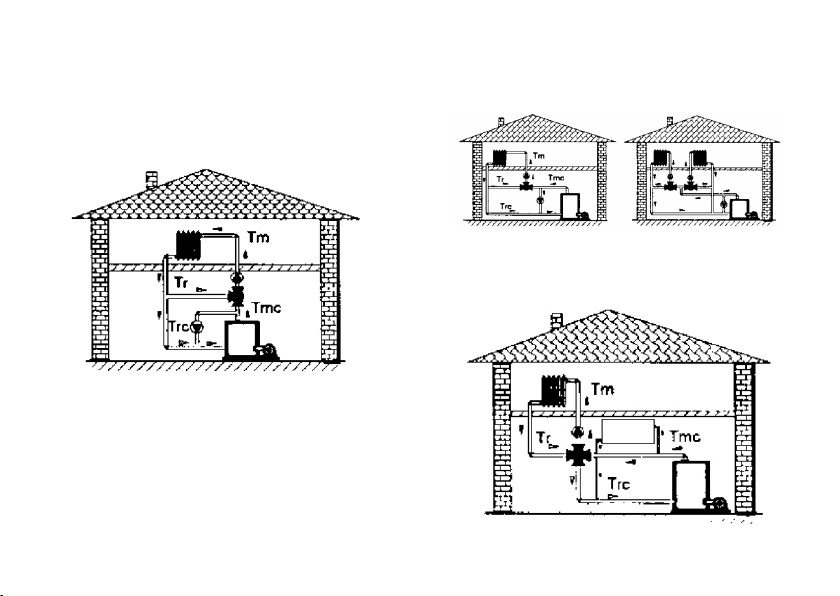
Avoid to make probe connections close to distribution
cables with high current loads.
Connect the different devices according to shown
diagrams.
Make sure that coupling connections are clean and
not oxidised.
Connect the control unit Fastons to the proper cou-
plings on the terminal base, pressing them down to
full bedding.
Then tighten the fastening bolt.
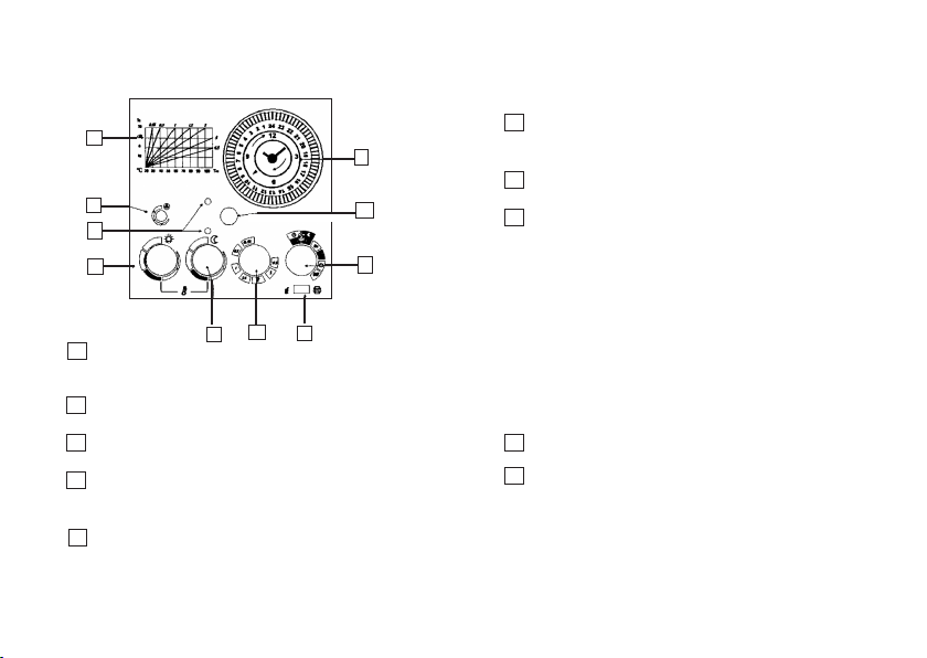
OPERATION TYPE SELECT SWITCH
Switch G (pg 6) shall be used for immediate selec-
tion between proportional-time control of motor-op-
erated mixing valves (wiring diagrams 1 and 2) and
burner ON/OFF control (wiring diagram 3).
CIRCULATION PUMP CONTROL
EV02F control unit is preset for automatic circulation
pump control.
If connections are carried out according to shown dia-
grams, the circulation pump will be working during the
following operating modes: AUTOMATIC 1, always
ON, always economy; and it will be off when in OFF
mode. It will also be off (with the exception of the an-
tifreeze protection) in the antifreeze operating mode
and at night in the AUTOMATIC 2 operating mode.
To make the most of the remaining heat accumulated
during the daytime mode, the pump will shutdown
(with 60-minute adjustable delay) after turning the
system off.
SERVO CONTROL OPERATION TEST
Turn control unit selector H (pg 6) to ON and OFF
positions, check for proper valve movement and com-
pare it with plate data.
When the selector is at OFF, the valve control lever
pointer shall move to COLD; when the selector is at
ON, the lever pointer shall move to HOT.
Otherwise exchange servo control connections 2 - 3
or connections 6 - 8 on the control unit base.
IN THE EVENT OF SYSTEM UNSUCCESSFUL
OPERATION CHECK THE FOLLOWING:
Supply voltage, that shall be: 230V 50Hz.
Probe circuit, by means of the tester provided for
measuring the resistance value.
Connections and settings of burner thermostats,
safety thermostats, etc.
Turn the daytime ambient temperature regulation
knob fully clockwise and counterclockwise for several
consecutive times: if the two pilot lamps turn on and

5
off the control unit is working regularly, check then the
servo control and the mixing valve.
Check for regular operation of couplers between ser-
vomotor and mixing valve control stem, and for ab-
sence of sliding caused by loosening of setscrews.
EXAMPLES OF ELECTRIC CONNECTIONS FOR
MIXING VALVE WITH SERVO CONTROL AND FOR
BURNERS
1 - Wiring diagram for motor-operated mixing
valves with servo controls powered with 230 V
50 Hz
Circulation pump supply
Servo control
Supply voltage
Common
Open
Close Delivery probe
EC12 - EC13
Outside
probe
EC11
230 V - 50 Hz
Circulation pump supply
Servo control
supply
Supply voltage
Supply voltage
Burner supply
Delivery probe
EC12 - EC13
Delivery probe
EC12 - EC13
Outside
probe
EC11
Outside
probe
EC11
230 V - 50 Hz
230 V - 50 Hz
Base with terminal board
2 - Wiring diagram for motor-operated mixing
valves with servo controls powered with voltages
other than 230V 50 Hz
3 - Schema elettrico per il comando ON-OFF del
bruciatore

6
F
G
H
I
L
nomy mode)
MAX = night ambient temperature same as day
ambient temperature.
Knob for selecting heating straight lines shown
in diagram A (see section “SETTINGS AND
ADJUSTMENTS”)
Switch for choosing between burner or power-
operated mixing valve control
Six-way selector to select the following:
- OFF
- always antifreeze: at this position the delive-
ry water temperature is always kept at + 5
°C at least, with whatever position of the other
controls (with burner ON)
- always economy
- ON
- Automatic 1 : nightime economy /daytime
comfort
- Automatic 2 : nightime antifreeze/ daytime
comfort.
Screw for mechanical connection between
electronic panel and terminal base.
Quartz clock for daily programming.
FRONT CONTROL PANEL
L
H
G
F
E
A
A
B
C
D
E
B
C
D
I
FANTINI COSMI EV02F
Indicative diagrams of delivery water temperatu-
re (20 ÷ 110 °C x-axis) as a function of outside
temperature (20 ÷ -40 °C y-axis).
Circulation pump shutdown control, with delay
up to 60 minutes.
LEDs showing valve movement (valve open or
valve closed); with LEDs off the valve is off.
Daytime ambient temperature regulation knob:
MIN = approx. 13 °C ambient temperature
MAX = approx. 27 °C ambient temperature
Nighttime ambient temperature regulation knob
(economy mode):
MIN = approx. 10 °C ambient temperature (eco-

7
INSTALLATION
EV02F CONTROL UNIT INSTALLATION
Fully loosen the fastening bolt to release the base of
the control unit. Lever on the slots with a screwdriver
to remove the base.
Secure the control unit terminal base to the wall (or
according to the mounting systems described in the
previous page) in a dry room, free from dripping.
EC11 OUTSIDE PROBE INSTALLATION
Install the outside probe in a vertical position on the
north or north-west wall of the building at about 2.5
metres at least from the ground. Install the probe far
from heat sources (windows, aerators, ues, etc.)
and protruding parts.
EC12 (contact probe) AND EC13 (immersion
probe) DELIVERY PROBE INSTALLATION
Install the contact probe EC12 onto the water pipe
with the clamp provided for the purpose and with heat
conducting paste interposed in order to guarantee
proper heat conduction.
The immersion probe EC13 must be tted in the pip-
ing with the sheath lled with mineral oil or silicone
grease.
NOTE The delivery probes must be mounted down-
stream the mixing valve at least 1.5 metres from the
valve, preferably after an elbow.
If the circulation pump is placed on the delivery side,
install the probe downstream the pump.
3- OR 4-WAY MIXING VALVE INSTALLATION
Install the mixing valve at boiler top edge level, in
handy position.
Check for no seizing between shutter and valve body
by operating the mixing valve manually; restore me-
chanical connection between servo control and valve
body.
When at closed position the mixing valves do not
guarantee perfect seal, it is therefore necessary to
install suitable gate valves or check valves on radia-
tor circuits in order to enable valve removal without
having to drain the circuit.

8
EXAMPLES OF HYDRAULIC CONNECTIONS FOR
MIXING VALVES
3-WAY SECTOR POWER-OPERATED MIXING
VALVE
3-WAY ROTOR POWER-OPERATED MIXING
VALVE
4-WAY ROTOR POWER-OPERATED MIXING
VALVE

9
SETTINGS AND ADJUSTMENTS
1) INITIAL CONTROLS POSITIONS
(see paragraph “front control panel”, page 6)
D at central area (comfort zone).
E fully rightwards at “MAX” position (same
temperatures for night and day).
H at Automatic 1 (nighttime economy/day-
time comfort).
F at position 2 for radiator heating, or at po-
sition 0,5 for panel heating.
B at central position (pump shutdown delay
of about 30 minutes).
2) Set the boiler thermostat so to keep water temper-
ature at approx. 80 - 90°C, then turn the system on.
3) After 24 hours the ambient temperature of a stand-
ard room shall be equal to 20°C. If temperature is
lower turn slightly knob F counterclockwise, if it is
higher turn knob F clockwise.
Check again temperature after 24 hours. If required
keep on adjusting knob F position like indicated in
the table below until obtaining 20°C in the room, with
whatever outside temperature (it is recommended
to check temperature in the afternoon and early in
the morning since outside temperature changes for
sure).
NOTE knob F shall be used to select the required
straight line in diagram A, i.e. the pointer indicates the
straight line slope on the diagram.
4) Under these conditions the control unit is set on
the system and knob F shall no longer be operated.
To obtain the required operating modes according to
the plate data, just use knobs D , E , G .
5) Then set the clock as described in paragraph
“QUARTZ CLOCK DAILY PROGRAMMING”

10
HOW TO CORRECT KNOB F POSITION
ACCORDING TO OUTSIDE TEMPERATURE:
If ambient
temperature .........
...rises
...rises
...lowers
...lowers
When outside
temperature
...........
...rises
...lowers
...rises
...lowers
Turn knob
F..........
...clockwise
...clockwise
...counterclockwise
...counterclockwise
QUARTZ CLOCK DAILY PROGRAMMING
FANTINI COSMI EV02F
1
2
1 set current time moving the dial clockwise
2 program ON and OF times using the indicators on
the 24-hour dial:
- indicators inwards: ON
- indicators outwards: OFF
OPERATIONAL INSTRUCTIONS
WINTER MODE DUTY
- Open the circulation pump gate valves
- Start the pump
- If the system is equipped with mixing valve: operate
the valve manually to remove any sediment deposi-
ted inside the valve and check for absence of seizure
between shutter and valve body, then restore the me-
chanical connection between servomotor and valve.
- Turn knob H to automatic 1 position (nighttime
economy/ daytime comfort).
- Check the timer and set current time.
If the heating system settings have not been chan-
ged with respect to the last winter mode duty, the
control unit is set yet. Otherwise repeat the ope-
rations described in paragraph “SETTINGS AND
ADJUSTMENTS”.

11
SUMMER MODE DUTY
(for systems with mixing valve).
When the boiler is used for sanitary water and you
have to exclude the heating system, perform the fol-
lowing operations:
a) turn control unit selector H to OFF position and
wait for about 10 minutes to allow the mixing valve to
close completely, then turn the system off.
b) stop water circulation pump.
c) close circulation pump gate valves to prevent hot
water inltration into radiator circuits during the sum-
mer, since mixing valves do not ensure perfect seal.
If the boiler is not tted with hot water system, the
previous operations are not necessary - the burner
shall however be turned off.
Fantini Cosmi S.p.A. reserves the right to make what-
ever technical and manufacturing modication with-
out prior notice.
NOTES
GB79088F
Table of contents
Other Fantini Cosmi Control Unit manuals
Popular Control Unit manuals by other brands

Monoprice
Monoprice RS-232 10761 Integration note

WAMGROUP
WAMGROUP VCP R03 Series Assembly and main instructions for use and maintenance

SMC Networks
SMC Networks VM1000 Series Operation manual

Madas
Madas M15-1 Installation

McIntosh
McIntosh C8 - SCHEMATICS instruction manual

Carrier
Carrier 50CJ Installation, operation and maintenance instructions

Samson
Samson 44-2 Mounting and operating instructions

TQ-Systems
TQ-Systems TQMLS1028A user manual

AERMEC
AERMEC WMT 10 Use and installation manual

Bardiani
Bardiani J-GIOTTO TOP Instruction, use and maintenance manual

Vag
Vag GA INDUSTRIES 930-T Installation, operation and maintenance manual

Camille Bauer
Camille Bauer EMMOD 205 operating instructions