User Guide 1
Use precautions to avoid damages to the product or injuries of users. Any actions against following contents will cause serious
issues such as malfunction, electric shock, or burn.
USE DC12V ONLY
DC12V
DO NOT USE AC INPUT
AC
INPUT
Do not cut or rejoion wires while product
is connected wth live power source
Maximum driver quantity per serial
connection is limited. Failure causes overload
of current and damages to the product
Refer to‘WIRE THICKNESS’table to use proper
LED module
Failure will cause dimmed output
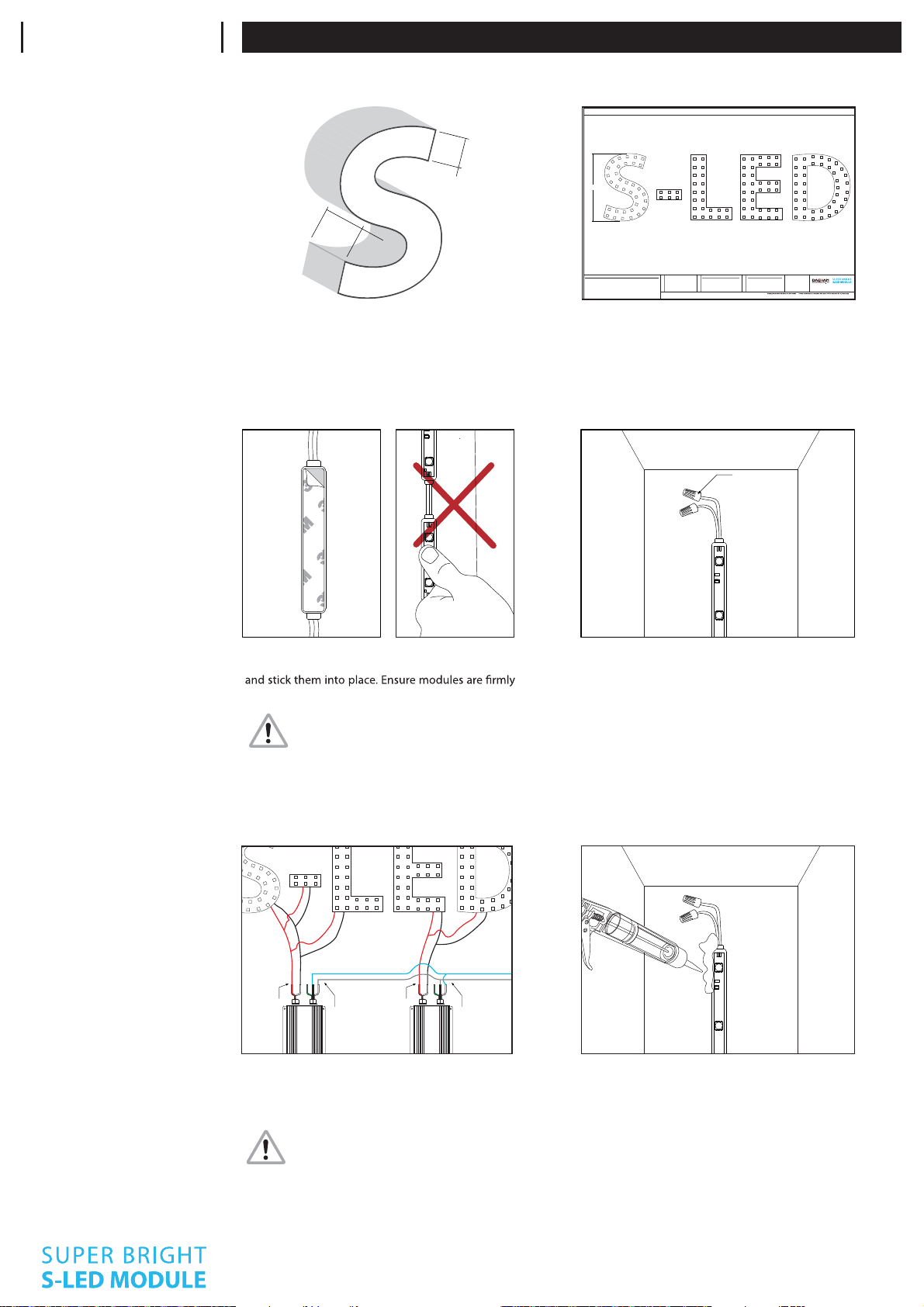
module is limited. Refer to ‘CONNECTION
WITH POWER SUPPLY’ on page 2
Do not use the product under circumstances
listed below
- High temperature spots over 60˚C (140˚F)
- Spots draw extreme moisture or dust
Avoid performing installation under rain or
high humidity for outdoor use
Do not perform actions listed below
- Alter or modify
- Touch LED lamps with sharp objects
- Put glue or silicon over the LED lamps
PRECAUTIONS
PREPARATION
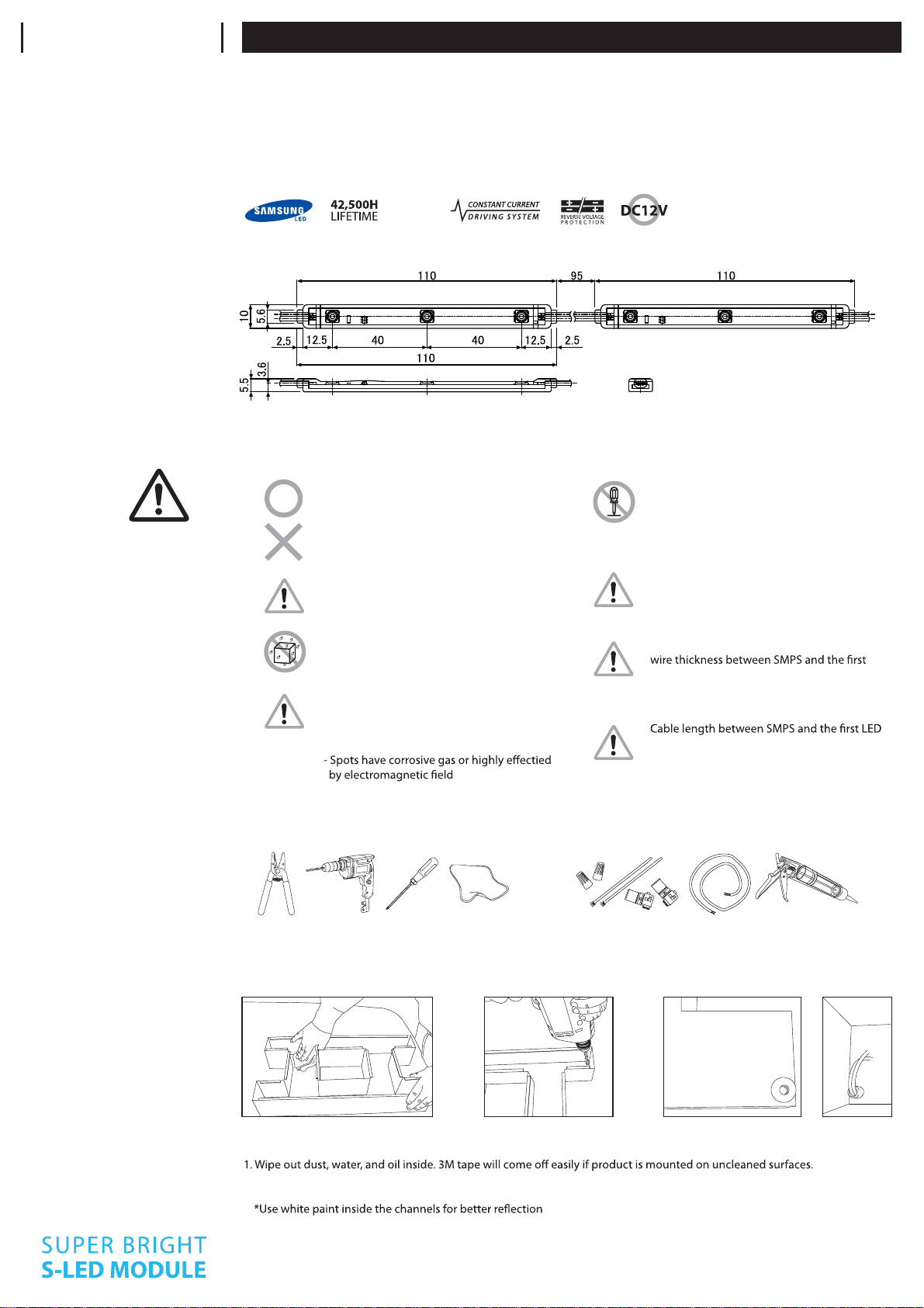
PREPARE CHANNELS
1. Clean moisture and dust inside 2. Make holes 3. Use bushing to protect wires
2. Make holes for wires from modules to SMPS.
3. Without bushins, wires will easily be cut and short-circuit will occur.
SUPPLIES REQUIREDTOOLS REQUIRED
Wire Nuts, Cable Ties, IDC Connectors, VCTF(PLTC) Cable,
(Optional : Silicon and Screws)
Wire Stripper, Drill, Screw Driver, Wiper
STAR C0340
PHYSICAL
ELECTRICAL
Current dissipation: 50 mA (Colored: 38 mA)
Power Consumption: 0,6 W (Colored: 0,46 W)
Operating power : DC 12V
Maximum serial connection : 50 modules
Electronic dimming control supported
Constant current drive, Reverse voltage protection
THERMAL
Cooling : Ambient air
Maximum operating temperature : 60˚C (140˚F)
Minimum operating temperature : -25˚C (-13˚F)
Maximum storage temperature : 60˚C (140˚F)
Minimum storage temperature : -30 C (-22 F)
SPECIFICATIONS
IP63
FARD lighting GmbH Seestrasse 20 D - 14974 Ludwigsfelde OT Genshagen
Tel. +49 - (0)3378 / 2003-0 Fax +49 - (0)3378 / 2003-29