FARMTECH T-DCBM-4 User manual


3
Thank you for choosing TURKAY!
As Turkay Company, introduce you Rotary Dısc Mower that provides a very low and high-
quality cutting on the evened ground where it leaves spread the grass it has reaped with its
high-quality cutting by leaving a one-type stubble.
Safe, trouble free operation of your implement requires that you and anyone else who will be
operating or maintaining it, read and understand the safety and operating instructions.
Keep this manual handy for future reference. Contact your dealer if you need assistance,
information or additional copies of this manual.
General Safety Information
Note the use of the signal words Danger, Warning and Caution with the Safety messages.
The appropriate signal word each has been selected using the following guidelines:
Danger!
Indicates an imminently hazardous situation that, if not avoided, will
result in death or serious injury. This signal word is to be limited to
the most extreme situations typically for machine components,
which, for functional purposes, cannot be guarded.
Warning!
Indicates a potentially hazardous situation that, if not avoided, could result in death or serious
injury, and includes hazards that are exposed when guards are removed. It may also be used
to alert against unsafe practices.
Caution!
Indicates a potentially hazardous situation that, if not avoided, may result in minor or
moderate injury. It may also be used to alert against unsafe practices.
Safety of the operator is one of the main concerns when designing and developing a new
piece of equipment. You, the operator, can avoid many accidents by observing the following
precautions in this section.
Replace any CAUTION, WARNING, DANGER or instruction safety decal that is not
readable or is missing.
Do not attempt to operate this equipment under the influence of drugs or alcohol.
Review the safety instructions with all users.
This equipment is dangerous to children and persons unfamiliar with its operation. The
operator should be a responsible adult familiar with the equipment and its operation. Do not
allow persons to operate this unit until they have developed understanding of the safety
precautions and of how it works.

4
To prevent injury or death, use a tractor equipped with a Roll Over Protective System
(POPS). Do not paint over, remove or deface any safety signs or warning decals on your
equipment, Observe all safety signs and practice instructions on them.
Never exceed the limits of a piece of machinery. If its ability to do a job, or to do so safely, is
in question –Don’t try it.
Remember - Your best assurance against accidents is a careful and responsible operator. If
there is any portion of this manual or function you do not understand, contact your local
dealer or manufacturer.
If you have questions not answered in this manual or require additional copies or the manual
is damaged, please contact your dealer or TÜRKAY company.
SAFETY TRAINING
Safety is a primary concern in the design and manufacturing of our product.
Unfortunately, our efforts to provide safe equipment can be wiped out by a
single careless act of an operator or bystander.
In addition to the design and configuration of equipment, hazard control and
accident prevention are dependent upon the awareness, concern, prudence and proper
training of personnel involved in the operation, transport, maintenance and storage of this
equipment.
It has been said, “ The best safety device is an informed, careful operator.” We ask you to be
that kind of operator. It is the operator’s responsibility to read and understand all safety and
operating instructions in the manual and to follow them. Accidents can be avoided.
Working with unfamiliar equipment can lead to careless injuries. Read this manual, and the
manual for your tractor, before assembly or operating, to acquaint yourself with the
machines. If this machine is used by any person other than you, or is loaned or rented, it is
the rotary tiller owner’s responsibility to make certain that the owner's manual be available to
the operator prior to operating:
Reads and understands the operator’s manuals.
Is instructed in safe and proper use.
Know your controls and how to stop the tractor, engine, and tiller quickly in an emergency.
Read this manual and the one provided with your tractor.
Train all new personnel and review instructions frequently with existing workers. Be certain
only a properly trained and physically able person will operate the machinery. A person who
has not read and understood all operating and safety instructions is not qualified to operate
the machine. An untrained operator exposesm himself and bystanders to possible serious
injury or death.

5
INTRODUCTION
Turkey Rotary Disc Mover is the MOST IDEAL machine type especially for the feed plants
growing horizontally such as vetch, white clover, Lotus corniculatus and for reaping all kinds
of meadow, pasture and feed plants and wild plants with the effect of the air current formed
during the rotate of the discs.
It is driven by the tractor tail spindle and connected to it with three point hitch system. The
movement is transmitted serially through its four fold belt pulley. The machine has 4-5-6 disc
models. It has a safety mechanism against the damage which may occur if it hits a hard and
big object (tree, stone, etc). It reduces the damage to a minimum by moving backwards when
it hits an object. The Disc Mover rises up by hydraulic system. So the machine stays behind
the tractor in transport position. Grass-cutting is performed on sloppy grounds after the
machine is made suitable to the slope through the hydraulic piston. The grass that has been
cut can be picked according to the desired sizes by the direction changer part that is
connected to the rear part of the machine.
It provides a very low and high-quality cutting on the evened ground where it leaves spread
the grass it has reaped with its high-quality cutting by leaving a one-type stubble.
TRANSPORTING :
Attention!
When the machine tied tractor and tractor is working
Never carry anyone or any animal on the machine.
Pay attention on the traffic rules on public roads.
Check out the lightening, warnıng decals, and protection guards before starting to
work.
Pay attention to work with the machine in the daylight. Especially at nights in public
roads take care to have safety decal (light decal apparatus) on the machine.
Transporting the machine,
1. Transporting with forklift: You must choose a forklift according to the weight of the
machine. Hold the machine from its weight center. Connect the forklift hook on the machine
from the weight center. Start transporting the machine.
2. Transporting with crane: This method is same as transporting with forklift. Hold the
machine from its weight center by crane. Pay attention if the security lock of the crane’s hook
is workng safely.
3. Transporting with palette: Choose palette according to the machine dimensions.
Transport the machine by forklift while it is on palette.

6
Never be under the machine or near the machine while transporting it by forklift, crane or
palette.
Take care of the security of the hook and iron ropes. Be sure that they are full of security.
Pic. 1- Main parts of the machine
1. Main Chassis
2. Cutter Bar
3. Discs
4. Hydraulic Cylinder
5. Three Point Hitch System
ATTENTION!
PAY ATTENTION TO BE NOT UNDER THE MACHINE
WHILE TRANSPORTING
ATTENTION!
TAKE CARE OF THE HOOKS AND IRON ROPES OF THE
CRANE AND FORKLİFT TO BE SAFETY ENOUGH

7
PREPARATION AND RUNNING OF THE MACHINE
Connecting the machine to the tractor:
Connect the Rotary Disc Mower to tractor by its three point hitch system.
At the same time put top and bottom safety pins according to convenient category.
(Note: Tractor max draw power till 40 HP are stated Category I, draw power which is
between 40-100 HP are stated Category II.)
For this reason top and bottom pins diameters will be selected according to category I and
category II and wear them.
Rotary Disc Mower machine is aranged acording to category II. See Table-1
Insert the safety pin.
Arrange the top and bottom arms so that the machine is paralel to the land.
(Note: Meanwhile tractor must be in a smooth surface.)
category
Max draw
power
(HP)
Bottom arm tractor connection pin:
hole diameterØ(mm)
(max.)-(min.)
Top arm draw connection pin:
hole diameter Ø(mm)
(max.)-(min.)
I
...40
22,10-21,84
19,56-19,3
II
40-100
28,45-28,19
25,91-25,7
III
80-225
36,85-36,32
32,26-32
IV
180-400
50,8-49,7
45,5-45,2
Table-1. (Sufficient tractor top and bottom arms connection pin and dimensions for attaching the
machine and tractor)
Working with Rotary Disc Mower machine:
Max. Input rotation speed of the Rotary Disc Mower is 540 RPM
Provide to reach selected tractor’s queue pin revolutions per minute convenient
revolutions per minute for the machine.
ATTENTION!
STOP THE ENGINE THEN ADJUST AND PREPARE THE MACHINE
FOR WORK

8
1-Upper hitch arm
2-Left hanger arm
3- Stretchning chains
4-Lower hitch arm
5-Right hanger arm
Pic.10 Connecting the machine to the tractor
Connecting the machine to the tractor:
Firstly connect the lower non adjustable arm then adjustable arm at the end connect upper
connection arm. While disconnecting the machine, do the opposite.
Connecting the pto shaft:
SERIES 4 P.T.O shaft which has Friction Limiter Clutch is used in Rotary Disc Mowers.
Before connecting the pto, clean the surfaces of spindle and lubricate them wtih grease.
Later shift the shaft on the pto spindle until the pin fits into safely. The shifting distance must
be at least 15 cm. Take pto shaft guard in a safety position by hanger. This safety position is
for the tractor and for the rotation of fixed parts.
P.T.O shaft can only be connected when the P.T.O connection and engine are switched off
and the ignition key is pulled down.
Connect the prescribed P.T.O. shaft and secure the P.T.O shaft connection by a chain
Make sure that the P.T.O shaft is in proper position on both ends. The adjustment of the
P.T.O shaft is necessary for different tractors. To find out the right length. Shorten both shafts
and proteciton tubes for exactly the same length.
To find the right length:
Connect the machine to the tractor.
Pull out the P.T.O shaft entirely and connect each separate half of the shaft to the tractor and
compare them wih each other.
If the covering of the P.T.O shaft and P.T.O shaft does not run into the block at horizontal
position. In case you need to shorten the P.T.O shaft.Shorten the shaft in exactly the same
length.

9
Pic. 11 Cutting the shaft spindle for a suitable length for the tractor
Pay your attention to proper mounting and securing of the P.T.O shaft..
Make sure that nobody is in the area of danger of the implement before switching on the
P.T.O shaft connection.
After switching off the P.T.O shaft conneciton the danger of rotating heavier parts remains.
Do not get close to the implement during this period. You can start to work only when the
rotation is completely stopped.
P.T.O shaft protection must be fitted on and must be in perfect condition..
Use only original P.T.O shafts prescribed by your manufacturar. Because the manufacturer
will not take any responsibility if another shaft is used.
When the machine is taken to the farm:
Start the engine of the tractor for a minute. Hold the machine with main hydraulic arm. Attach
the security lock for not to damage to the hydraulic system while driving. Stretch the
stretching chains to prevent swinging.
Attention!
When the machine is working, don’t intervene the machine with
hand, foot, foreign tools strictly.

10
When using the road queue pin, be careful that Revolutions Per Minute depends on
tractor’s speed and turning way can’t be opposite in back movement.
In machine’s carrying position, take care of from tractor wheels, excess outside.
The movements in curves, take care of freight condition and drift mass of the machine.
It’s dangerous to work with tractor in downhill.
Still If you have to do it, take care about it and don’t turn curves so severe.
To provide a safe movement stability, to cultivate the downhill working field; take care
of fitting the tractor with sufficient addition weight.
Before starting up in farm:
Put tractor hdyraulic control arm to position control condition and make the height
adjustment.
In position control condition, when you are moving hdyraulic arm a little, tool lifts up, stops in
a level, if you move the arm again, it lifts some more and stops, namely draw doesn’t rise the
top point like in control.
Note: Hdyraulic setdown-lifting arm is lifted up and put it in a certain level.
In this condition tool and machine completely lift up, front elect arm is in “DRAW CONTROL”
If tool and machine don’t lift completely, and lift in a certain level, it’s in “POSITION
CONTROL”.
Position control condition provides the machine’s working in the field by putting tool and
machine which are depended hdyrolic connection arms in a certain height.
When you’re working with like Centrifuge fertilizer distributed machine, front election arm
must be in position control condition.
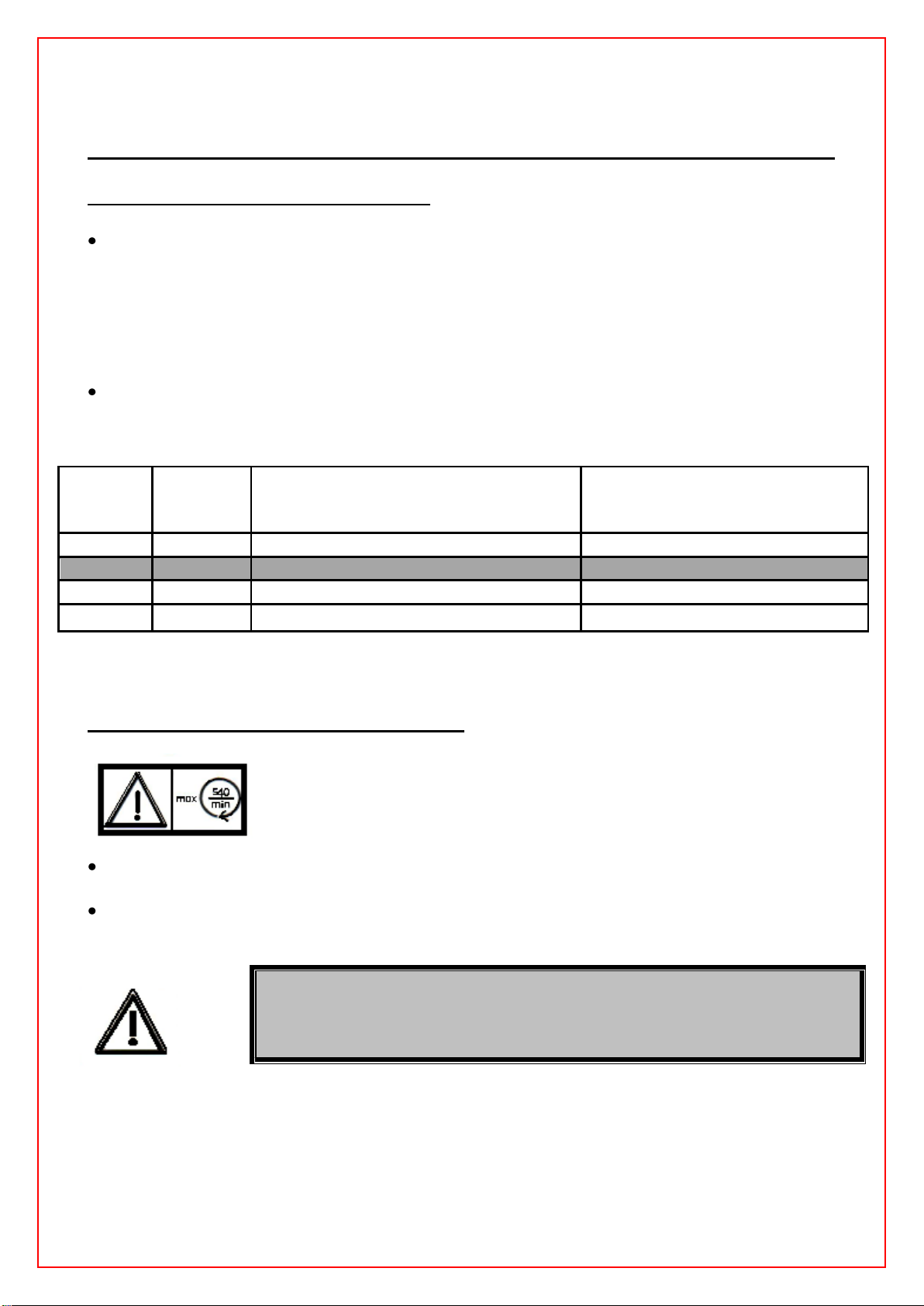
Safety Max. Input rotation speed of the Rotary Disc Mower is 540 RPM
After providing a convenient dept, the machine is taken to the field with a convenient gear it is
started up moving on and working.
Running and stopping of Hdyraulic Side Shifting Rotary Tiller is arranged only from tractor
driver place.
Rotary Disc Mower must works into the circle that has 5 m distance between itself and
people. Because in this field pieces that machine throws like stone and soil may come.
Rotary Disc Mower is worked only in flattened smoothy field.
Besides, be careful about if stone and chips exist in the field or not.
Then these strange materials is in working field, it can cause harm to machine’s cultivation
bodies, knives, and at the same time herbals and people.
Rotary Disc Mower don’t be worked in nonsmoothy fields.
Machine’s working speed is arranged only by depending working conditions.
During working with the machine, in the end of the turnings tractor queue spindle is
stopped and you wait until the machine is stopped.
Before the turnings the machine is lifted and slinged. So danger of throwing field pieces
which the machine’s got disseapears.
If your tractor which you run Rotary Disc Mower with doesn’t have a close driver cabin,
please during the working use a protection glasses and noise.

11
MAINTENANCE AND REPAIR
ATTENTION!
MAINTENANCE, REPAIRS, CLEANING MAY ONLY BE
EXECUTED WHEN THE DRIVE AND THE ENGINE ARE
SWITCHED OFF AND THE IGNITION KEY IS PULLED OUT.
Rotary Disc Mower is produced by full of quality.So this machine will not need so much
maintenance and repair after working with the machine.
Take care about the items that is written below for maintenance and repair :
Cleaning, lubrication or adjusting of the implement,driven by the P.T.O shaft can be done
when the connection and the engine are switched off and the ignition key is pulled out.
Maintenance and repair must be done after the shaft and machine is disconnected from the
tractor.
It is easy to repair and make maintenance to the Rotary Disc Mower.
Put the machine in a closed area after work,lubricate the parts and take care against rust.
Control the nuts and screws every day to see if they are tightened enough.If not tighten
them.
Change the broken and weared parts.
Choose the suitable parts while making maintenance.The parts must be safety.
Use adequate tools and gloves during repairs,mainteance and cleaning.
Lubricate the grease nipples periodically as shown in Pic.18-19.
Use original spare parts.
Control the gear box oil level in each 50 hours of work.Change the oil of the gear box after
controlling the oil level in the period of 100 hours work.Use SAE 140 oil in the gear box.Fill 5
litres of SAE140.
If you perform any maintenance on the lifted implement,always secure the implement by a
suitable holder.
Call Türkay technical service for the maintenance of the machine.
Table 7- Maintenance Periods
CONTROL(A)
MAINTENANCE(B)
VARIATION(C)
Maintenance Period
Daily
Weekly
50
hours
100
hours
400
hours
Greasing
(control of transmission oil
level)
Changing of oil (SAE140)
A
C
Control of oil leak
A
Control of knife corrosion
A
Lub. grease nipples
B
Control of tightness
(bolt-nut)
A
C
Cleaning
B

12
SECURITY LABELS LOCATIONS
The types of Security labels and locations on the equipment are shown in the illustration
below. Good Safety requires that you familiarize yourself with the various decals, the type of
warning and the area, or particular function related to that area, that requires your SAFETY
AWARENESS.
NOTE: The numbers represent the Security labels.
Security labels:
There are three types of security labels:
Danger!
Indicates an imminently hazardous situation that, if not avoided, will result in death or serious
injury. This signal word is to be limited to the most extreme situations typically for machine
components, which, for functional purposes, cannot be guarded.
Warning!
Indicates a potentially hazardous situation that, if not avoided, could result in death or serious
injury, and includes hazards that are exposed when guards are removed. It may also be used
to alert against unsafe practices.
Caution!
Indicates a potentially hazardous situation that, if not avoided, may result in minor or
moderate injury. It may also be used to alert against unsafe practices.
Do not open or remove safety shields while the engine is
running
Stay clear of mower knife area as long as tractor engine is
running
Wait until all machine components have completely stopped
before touching them

13
Shut off engine and remove key before performing
maintenance or repair work
Stay clear of swinging area of implements
Never reach into the crushing danger area as long as parts
may move
REMEMBER: If safety signs have been damaged, removed, become illegible or parts have
been replaced without signs, new safety signs must be applied. New Safety signs are
available from your authorized dealer, distributor or factory.
WORKING SAFETY
Stop the machine if it is windy or use wind guard against wind.
Safety and warning decals, placed on the machine, give important instructions for safe
work. Take them into consideration for your safety.
Make sure you get familiar with all devices and elements for handling and with the
functions before starting with the work.
Avoid wearing loose-fitting clothes. Clothes should fit tight to the operator’s body.
Implements should be connected according to the instructions, fastened to the prescribed
devices and secured.
Never left the driving seat during driving.
Strating devices for remote control should be secured in a way that, they can not be
unintentionally released during transport or work.
When disconnecting the machine from the tractor, place it on the flat ground.
Never jump, sit or climb on the machine while it is connected to the tractor.
Stopping or operating the machine must be done by the driver. No one may drive the
tractor except the driver.
Use protection for hearing and glasses while working with the machine if the tractor does
not have a closed cabin.

14
TECHNICAL DOCUMENTS
Tablo 4 –Technical specification

15
CUSTOMER SERVICES AFTER SALES, SERVICE AND SAPARE PARTS
MANUFACTURER INFORMATION :
TÜRKAY AGRICULTURAL MACHINERY
Address: Fatih Mah. 191 Sk. No:17 Sarnıç /IZMIR
Phone number: 0090 232 281 54 04 / 281 63 30 / 281 63 31
Fax: 0090 232 281 57 10

16
EC DECLARATION OF CONFORMITY
TURKAY TARIM MAKINALARI SAN. VE TIC. LTD. STI.
Fatih Mah. 191 Sok. No: 17 Sarnıc, Gaziemir / IZMIR / TURKIYE
Declare under our own responsibility that the product(s) specified below satisfies the
requirements of the Machinery Safety Directive 2006/42/EC.
The product(s) identified below has been produced according to basic safety and health
measures.
BRAND: TURKAY
PRODUCT TYPE: ROTARY DISC MOWER
PRODUCT CODE: T-DCBM-4 / T-DCBM-5 / T-DCBM-6
Harmonized standards:
TS EN ISO 14112-1:2007 / Safety of machinery-Principles for risk assessment
TS EN ISO 12100-1:2003+A1:2009 / Safety of Machinery-Basic Concepts General Principles
for Design Par 1:Basic Terminology, Methodology
TS EN ISO 12100-2:2003 +A1:2009 / Safety of machinery; safety distances to prevent
danger zones being reached by the upper limbs
TS EN ISO 13857:2008 / Safety distance to prevent danger zones being reached by the
upper limbs
TS EN 349:1993+А1:2008 / Safety of machinery - Minimum Gaps to Avoid Crushing of Parts
of the Human Body
TS EN 745:1999+А1:2009 / Agricultural machinery- Rotary mowers and flail mowery safety
Issued at IZMIR-TURKEY, March 03.2011
Authorized Signatory
Şaban BATUR
Production Manager

17
SPARE PART LİSTS
1. Makina Son Montajı TDCBM4–1 / TDCBM5–1 / TDCBM6–1

18
1. YEDEK PARÇA LİSTESİ
1. Makine Son Montajı TDCBM4-1 / TDCBM5-1 / TDCBM6-1
Poz.
Numarası
Miktar
Sipariş Numarası
Açıklama
Standart
01
1
TDCBM4–1.1
TDCBM5–1.1
TDCBM6–1.1
Biçme Düzeni Montajı 4’lü
Biçme Düzeni Montajı 5’li
Biçme Düzeni Montajı 6’lı
10402001.111.000000000
10402002.111.000000000
10402003.111.000000000
02
1
TDCBM4–1.2
Amortisör Grubu
10402001.050.000000000
03
1
TDCBM4–1.3
Piston Grubu
10402001.040.000000000
04
1
TDCBM4–1.4
Üç Nokta Askı Grubu
10402001.040.000000000
05
1
TDCBM4–1.5
HOR-HID-VANALI-1/2"-3/8"R1-
185cm
92100.0402001.001
06
1
TDCBM4–1.6
Ara Gövde Kilidi
10402001.101.000000000
07
1
TDCBM4–1.7
Emniyet Kilidi Grubu
10402001.061.000000000
08
1
TDCBM4–1.8
Ara Gövde Grubu
10402001.010.000000000
09
1
TDCBM4–1.9
TDCBM5–1.9
TDCBM6–1.9
Muhafaza ve Perde Montajı
10402001.020.000000000
10402002.020.000000000
10402003.020.000000000
10
1
Hidrolik Vana G3/8
Hidrolik Vana G3/8
11
1
TDCBM4–1.3.5
Bağlantı Rekoru G3/8
10402001.040.022000000
12
3
RON-BAK–G3/8
Bakır Rondelâ G3/8
93061.0000000.002
13
2
TDCBM4–1.13
Pim
10402001.133.000000000
14
1
CIV-AKB-M22x80
Altı Köşe Başlı Cıvata
15
3
YARIKLI PİM
YARIKLI PİM Ø6x36
93200.0000000.009
16
1
SOMFIB-AKB-M22
Fiberli Somun
17
1
TDCBM4–1.17
Büyük Yönlendirme Disk
10402001.080.000000000
18
1
TDCBM4–1.18
Küçük Yönlendirme Disk
10402001.070.000000000
19
1
TDCBM4–1.19
Ara Gövde Bağlantısı
10402001.091.000000000

19
1.1 YEDEK PARÇA LİSTESİ
1.1 Kesici Takım Montajı TDCBM4–1.1 / TDCBM5–1.1/ TDCBM6–1.1

20
1.1 YEDEK PARÇA LİSTESİ
1.1 Kesici Takım Montajı TDCBM4–1.1 / TDCBM5–1.1/ TDCBM6–1.1
Poz.
Numarası
Miktar
Sipariş Numarası
Açıklama
Standart
01
2
TDCBM4–1.8.10
Bronz Yatak
02
1
TDCBM4–1.1.2
TDCBM5–1.1.2
TDCBM6–1.1.2
Kesici Gövde Üst Sacı
03
16
20
24
RON-DÜZ-M12
Düz Rondelâ
04
16
20
24
CIV-AKB-M12x1.75x25
Altı Köşe Başlı Cıvata
05
4
5
6
TDCBM4–1.1.5
TDCBM5–1.1.5
TDCBM6–1.1.5
Alt Kızak
06
2
SIK-KOV-Ø10x10
Yarıklı Pim
07
2
3
4
TDCBM4–1.1.7
TDCBM5–1.1.7
TDCBM6–1.1.7
Bıçak Bağlantı Diski
08
1
TDCBM4–1.1.8
TDCBM5–1.1.8
TDCBM6–1.1.8
Kesici Gövde Alt Sacı
09
1
TDCBM4–1.1.9
Büyük Kızak
10
1
Raynel
Raynel
11
1
Raynel Ø80
Raynel Ø80
12
1
TDCBM4–1.1.12
13
1
RUL–6208
Rulman
14
1
TDCBM4–1.1.14
Düz Dişli Z:45
15
1
TDCBM4–1.1.15
16
1
TDCBM4–1.1.16
Şanzıman Montajı
17
2
TDCBM4–1.1.17
Tapa 3/8”
18
2
RONDEL–3/8”
Rondelâ 3/8”
19
4
SOMFIB-AKB-M8
Fiberli Somun
20
4
CIV-AKB-M8x1.25x20
Altı Köşe Başlı Cıvata

21
1.1 YEDEK PARÇA LİSTESİ
1.1 Kesici Takım Montajı TDCBM4–1.1 / TDCBM5–1.1/ TDCBM6–1.1
Poz.
Numarası
Miktar
Sipariş Numarası
Açıklama
Standart
21
2
RON-DÜZ-M10
Düz Rondelâ
22
2
CIV-AKB-M10x1.5x20
Altı Köşe Başlı Cıvata
23
61
75
89
SOMFIB-AKB-M10
Fiberli Somun
24
49
60
71
CIV-AKB-M10x1.5x30
Altı Köşe Başlı Cıvata
25
4
5
6
CIV-AKB-M10x1.5x55
Altı Köşe Başlı Cıvata
26
4
5
7
TDCBM4–1.1.26
Burç
27
8
CIV-IMB-M12x1.75x35
Cıvata Silindirik Başlı
İmbus
28
4
TDCBM4–1.1.28
Küçük Bağlantı Parçası
29
8
SOMFIB-AKB-M12
Fiberli Somun
30
4
5
6
RON-DÜZ-M10
Düz Rondelâ
31
4
5
6
CIV-AKB-M10x1.5x20
Altı Köşe Başlı Cıvata
32
8
10
12
CIV-AKB-M10x1.5x24
Altı Köşe Başlı Cıvata
33
1
TDCBM4–1.1.33
Küçük Kızak
34
…
6
10
TDCBM4–1.1.34
Düz Dişli Z:45
35
10
11
12
TDCBM4–1.1.35
Özel Bağlantı Mili M20
36
10
11
12
TDCBM4–1.1.36
Özel Bağlantı Somunu
M20
37
10
11
12
TDCBM4–1.1.37
Yatak Burcu
38
10
11
12
TDCBM4–1.1.38
Özel Rondelâ
This manual suits for next models
2
Table of contents
Other FARMTECH Farm Equipment manuals
Popular Farm Equipment manuals by other brands

KUHN
KUHN FC3160TCD Operator's manual

Land Pride
Land Pride RTR1550 Operator's manual

Steketee
Steketee EC-RIDGER 7 operating instructions

Croplands
Croplands US20F/252/HR30 Operator's manual

Kellands
Kellands AGRIBUGGY 1000 Operator's instruction manual

Multiva
Multiva FX300 SeedPilot Operation and maintenance manual