12
DE
MONTAGE AUF ISOCLAIR-ZYLINDER Ø 8 bis 63:
1- Näherungsschalter auf das Klemmband stecken.
2-
Schraube in den Näherungsschalter eindrehen und festziehen.
3- Klemmband öffnen.
4-
Einheit aus Näherungsschalter und Klemmband um das Rohr legen.
5- Einheit am Abtastpunkt positionieren.
6- Einheit auf dem Zylinder festziehen.
Zur Montage des Näherungsschalters mit elektrischem Ans-
chluss hinten ist die Einheit aus Näherungsschalter und
Klemmband um 180° zu drehen.
ZurKontrollederPositionenan den Enden des Zylinders müssen
dieNäherungsschaltermitEinbausteckern so montiert werden,
dass die Einbaustecker zur Zylindermitte ausgerichtet sind.
Möglichkeit der Befestigung von Näherungsschaltern zur
Überwachung der Zwischenstellungen.
1- Bügel auf den Näherungsschalter stecken.
2- Schraube in den Näherungsschalter eindrehen.
3- Einheit auf eine der vier Buckeln montieren und am Abtast-
punkt positionieren.
4- Der Näherungsschalter muss auf dem Rohr aufliegen,
anschließend die Einheit festziehen (Inbusschlüssel 2 mm).
MONTAGE AUF PES-ZYLINDER MIT
PROFILROHR Ø 32 bis 125 :
Möglichkeit der Befestigung von Näherungsschaltern zur
Überwachung der Zwischenpositionen.
A
1- Näherungsschalter auf die Klemmbacke stecken.
2- Schraube in den Näherungsschalter eindrehen und festziehen.
3- Einheit auf einen der 4 Zuganker montieren und am
Abtastpunkt positionieren.
4- Der Näherungsschalter muss auf dem Rohr aufliegen,
anschließend die Einheit festziehen (Inbusschlüssel 3 mm).
Ø 32 bis 80 mm :
MONTAGE AUF PES-PIS ZYLINDER MIT
ZUGANKERN
1- Klemmband um das Rohr legen (unter den Zugankern). Die
zwei Enden müssen sich auf der Seite befinden, auf der sie
festgezogen werden sollen.
2- Klemmband lösen, jedoch nicht entfernen (die Schraube nicht
von der Halterung lösen).
3- Näherungsschalter auf die Kunststoffhalterung stecken.
4- Festschrauben.
5- Enden des Klemmbandes in die Aussparungen einlegen.
6-
Näherungsschalter mit der Halterung unter das Klemmband schieben.
7- Einheit aus Näherungsschalter umd Klemmband am
Abtastpunkt positionieren.
8- Der Näherungsschalter muss auf dem Rohr aufliegen,
anschließend die Einheit festziehen.
Ø 100 bis 200 mm :
Möglichkeit der Befestigung von Näherungsschaltern zur
Überwachung der Zwischenpositionen.
MONTAGE AUF K, P2L/P2B-ZYLINDER
I
II
III
B
I
C
I
Dsiehe nebenstehende Zeichnung
Zur Montage des Näherungsschalters mit elektrischem An-
schluss hinten ist der Näherungsschalter und der
Befestigungsbügel wie unten angegeben.
ZurKontrollederPositionen an den Enden des Zylinders müssen
die Näherungsschalter mit Einbaustecker so montiert werden,
dass die Einbaustecker zur Zylindermitte ausgerichtet sind.
II
III
Die Näherungsschalter können auf einen der vier Buckel
montiert werden.
IV
Möglichkeit der Montage der Näherungsschalter auf
Zylinderdurchmesser 32 bis 80 mm mit elektrischem An-
schluss hinten.
ZurKontrollederPositionen an den Enden des Zylinders müssen
die Näherungsschalter mit Einbaustecker so montiert werden,
dass die Einbaustecker zur Zylindermitte ausgerichtet sind.
II
III
Ø 32 bis 80 mm
Die Näherungsschalter können auf einen der vier Zuganker
montiert werden.
Ø 100 bis 200 mm (Befestigung mit Klemmband)
ZurMontagedesNäherungsschaltersaufZylinderdurchmesser
100 bis 200 mm mit elektrischem Anschluss hinten ist die Stütze
und der Näherungsschalter nach dem Lösen des Klemm-
bandes um 180° zu drehen (Klemmband nicht entfernen).
IV
V
*
21
E max.
D
;;;;;;;;;
;;;;;;;;;
;;;;;;;;;
;;;;;;;;;
;;;;;;;;;
;;;;;;;;;
;;;;;;;;;
;;;;;;;;;
;;;;;;;;;
E max.
;;;;;;;;;
;;;;;;;;;
;;;;;;;;;
;;;;;;;;;
;;;;;;;;;
;;;;;;;;;
;;;;;;;;;
;;;;;;;;;
;;;;;;;;;
32 40 50 63 80 100 125 160 200
D3034424755----
E 44475156637588106127
Ø cylinder
;;;;;;;;;;
;;;;;;;;;;
;;;;;;;;;;
;;;;;;;;;;
;;;;;;;;;;
;;;;;;;;;;
;;;;;;;;;;
;;;;;;;;;;
;;;;;;;;;;
;;;;;;;;;;
E max.
;;;;;;;;;
;;;;;;;;;
;;;;;;;;;
;;;;;;;;;
;;;;;;;;;
;;;;;;;;;
;;;;;;;;;
;;;;;;;;;
;;;;;;;;;
;;;;;;;;;
E max.
IV
I
II
III
V
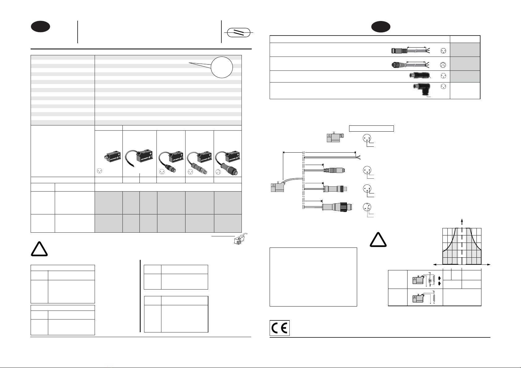
DTYPE K, KN, PEC, P2L/P2B
1
2
3
1
2
3
l
C. max: 0,4 N.m
N°1
11
DE
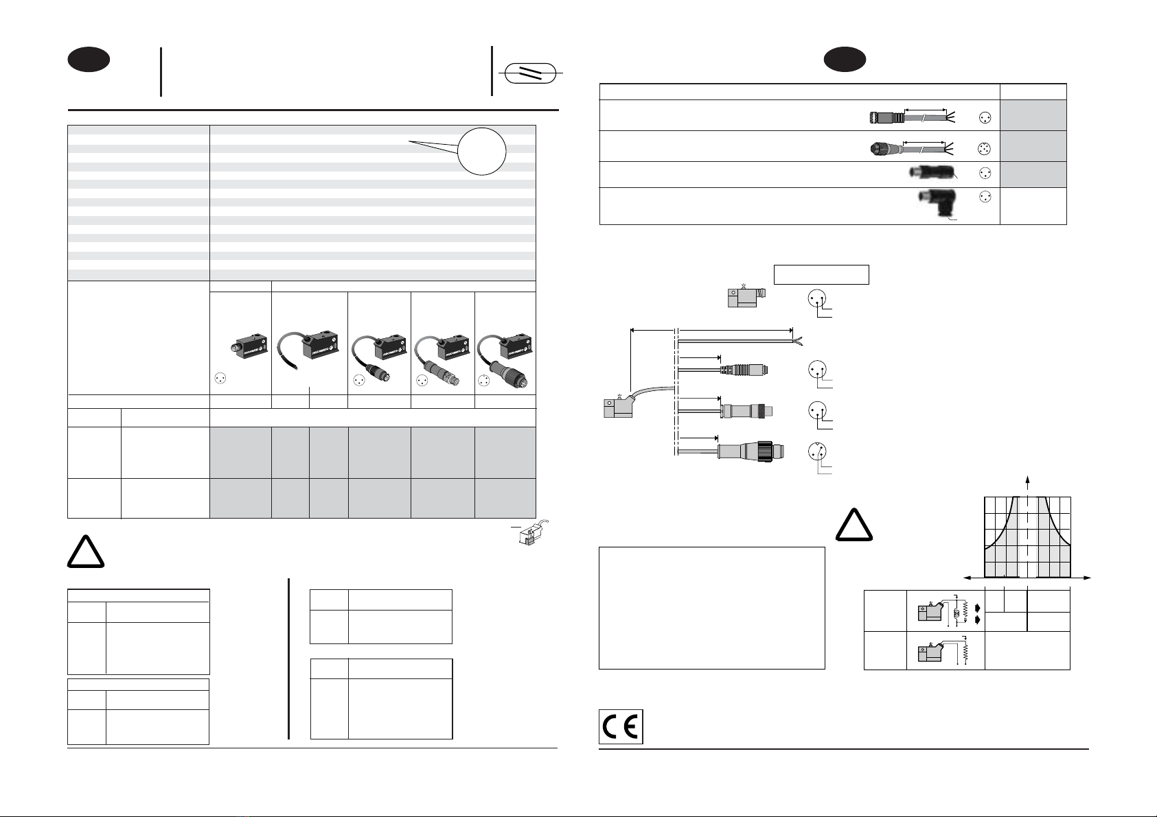
120 mm min
.
(X) (Y)
15 mm min.
r.
Zum festen Teil
min.
MONTAGE-EMPFEHLUNGEN
Achten Sie darauf, dass das Spannungsversorgungs-
kabel des Näherungsschalters während der gesamten
Lebensdauer ohne Zugbelastung verlegt und nicht ver-
dreht wird.
- Kabel ausreichend lang dimensionieren.
- Nicht an den Kabeln ziehen.
- Die Kabel nicht knicken.
- Bei einer statischen Montage ist ein Biegeradius
von mindestens 15 mm zu beachten.
- Darauf achten, dass die Kabel
insbesondere bei der Verwendung von
Zangen zur Montage des Klemmbands
nicht gequetscht werden.Der Mindestanziehmoment
(bei Kabel Ø 2 - 2,5 mm) ist unbedingt zu beachten.
Mobile Anwendungen:
Bei einer dynamischen Montage ist das Kabel aufgrund
des Gewichts der Leitungsdosen oder eines zu langen
Kabels Schwingungen ausgesetzt, die zu einem Bruch
des Kabels führen können. Die Leitungsdosen sind
deshalb an den Zylinder zu montieren.
Bei Anwendungen, in denen die Zylinder + Näherungsschalter großen Hüben
und Bewegungen ausgesetzt sind, sind die zu diesem Zweck vorgesehenen
Mini-Näherungsschalter mit M8-Einbausteckern (X) sowie die mit einem (2-
oder 3-adrigen) Verlängerungskabel der Klasse 6 ausgestatteten
Leitungsdosen (Y) zu verwenden [Sonderzubehör (auf Anfrage)].
- Kabel wie in nebenstehender Zeichnung verbinden und auf einen Biegeradius
von mindestens 120 mm achten.
- Näherungsschalter nicht neben intensiven ferromagnetischen oder
elektromagnetischen Störquellen (Magnetspulen, Schweißzangen)
montieren.
- Kabel aus PVC nicht in öligen Umgebungen oder mit inkompatiblen
Lösungsmitteln verwenden (Wir bitten ggf. um Rücksprache).
Reinigung mit einem alkalischen Mittel durchführen (Seifenwasser).
Anschluss der Näherungsschalter mit Einbaustecker:
- Näherungsschalter von Hand festziehen (Kein Werkzeug verwenden!)
INBETRIEBNAHME
- Die Näherungsschalter des Typs UNI müssen immer in Übereinstimmung mit
den in dieser Unterlage angegebenen technischen Daten (elektrische und
mechanische Kenndaten, Temperatur) verwendet werden. Jegliche
Nichteinhaltung kann zu einer Beschädigung der Näherungsschalter führen.
- Änderungen bedürfen der vorherigen Zustimmung von ASCO/JOUCOMATIC.