Page 2
Wiring Apply power only after all
connectionshavebeenmadeand
inspected. Do not coil excess
wiringinsidethe detector.
•Terminals 1 (-) & 2 (+): Voltagelimitsare9
to15VDC. Use nosmallerthan#22 AWGwire
pair (500 feet/150m max) between the detector
andthe power source.
• Terminals 3 & 4: Alarm relay (reed) contacts rated at 3 watts, 0.125 amps,
28VDCmaximumfor DC resistive loads and protected by a4.7ohm,1/2watt
resistor.
NOTE: Do not use with capacitive or inductive loads.
•Terminals 5 & 8: Spare.
•Terminals 6 & 7: Tampercontacts rated at 28VDC, 0.125A.
•
Plug the wire entrance hole with the foam plug that has been provided.
LED Operation
The detector uses a tri-color LED to indicate the various alarm and supervision
troubles that may exist. See chart below:
If the detector experiences a Microwave or PIR self-test failure, it is in need of
replacement.
During walk testing, the LED will light for the first technology (microwave or
PIR) and then light red to indicate a detector alarm. The LED will not indicate
activationof the second technology by lightingits color.
Feature Selection
LED On/Off pins: The ON position allows
operation of the tri-color LED. If the tri-color
LEDindication is not desiredafter the setup
andwalk tests have been completed, place
theplug in the OFF position.
NOTE: TheOFF position does not prevent
thetri-color LED from indicating a
supervisiontroublecondition.
PIR Sensitivity Selection Pins: Selection of the PIR response sensitivity
may be selected by placing the plug across the pins marked STD for standard
orINTforintermediatemode.
Standard Sensitivity:
Thisis the recommended setting for maximumfalse
alarmimmunity. It toleratesenvironmentextremes on this setting.
Intermediate Sensitivity:
Therecommendedsetting for any location where
an intruder is expected to cover only a small portion of the protected area. It
toleratesnormal environments on this setting. This settingwill improve your
intrudercatchperformance.
Set-up and Walk Tests
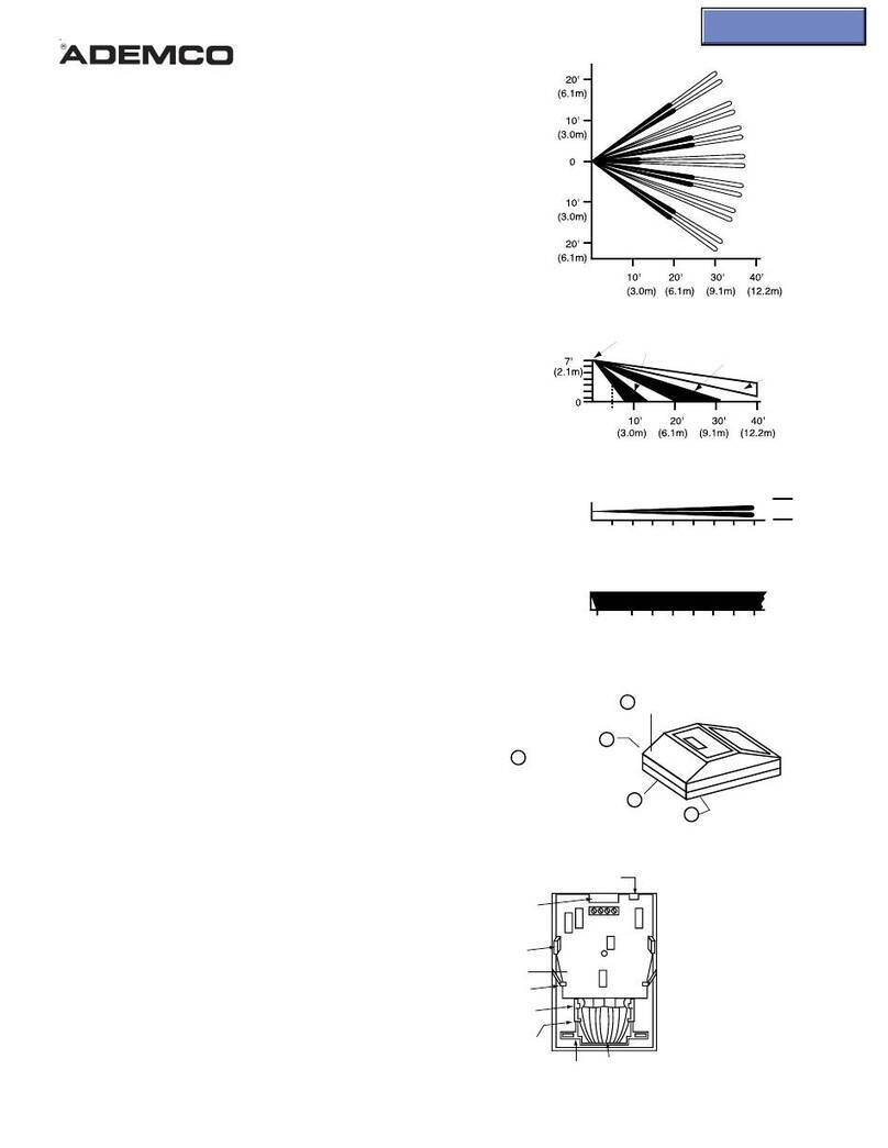
Selectthe vertical starting anglefrom the chart
tothe right.
Adjustthe vertical starting angle for thedesired
mountingheightandrange.
• Place the LED plug in the ON position and
replacethecover.
•Wait at least two minutes, after applying power, before starting walk tests.
NOTE: During the warm-up period, the tri-color LED will flash red until the unit
has stabilized and has seen no movement for two seconds (approxi-
mately one to two minutes). When the LED stops flashing, the
detector is ready to be tested. With no motion in the protection area,
the LED should be OFF. If the LED is on, re-check the protection
area for disturbances affecting the microwave (yellow) or PIR (green)
technologies.
Establishing PIR pattern coverage
• TurntheMicrowave range adjust to minimum.
• Walktest across thepatternatitsfarthestedge,thenseveraltimescloserto
thedetector. Start walkingfrom outside of the intendedprotection area, and
observe the tri-color LED. The edge of the pattern is determined by the first
green,PIRactivationoftheLED (or the first red activation if the yellow micro-
wave LED activates first).
• Walktestfrom the opposite direction to determine both boundaries. The cen-
terofthepatternshouldbepointedtowardthe center of the intended protec-
tionarea.
• Slowlybringyour arm up and into the patterntomarkthe lower boundary on
PIRalarm.Perform this task at 10 to 20 ft.(3.1to6.1m)from the unit. Repeat
from above for the upper boundary. The center of the pattern should not
be tilted upward.
Ifdesiredcoveragecannotbeachieved,tryangling the coverage pattern up
ordownto assure the pattern is not aimedtoohighor low. The angle of the
PIR pattern may be vertically positioned between -10° and +2° by loos-
eningthe VerticalAdjust screw and slidingthe circuit board upor down.
Moving the board up will angle the pattern downward.Tightenthe screw
snugwhenpositioningiscompleted.
NOTE: The pattern may be moved ±10° horizontally by moving the lens
windowleft/right.
Establishing Microwave Coverage
NOTE: Itis important to wait one minute afterremoving/replacing the cover
so the microwave portion of the detector can settle, and to wait at
least10 seconds between the following walk testingprocedures.
• The tri-color LED should be OFF before walk testing.
• Walk test across the pattern at the intended coverage’s farthest end. Start
walking from outside the intended protection area and observe the tri-color
LED. The edge of the microwave pattern is determined by the first yellow,
microwave activation of the LED (or the first red activation if the green PIR
LED activates first).
• Ifadequaterangecannotbereached,increasethe Micro-
wave Range Adjust slightly.Continue walk testing (wait-
ing one minute after removing/replacing the cover) and
adjusting the range until the farthest edge of desired cov-
eragehasbeen accurately placed.
Donotadjust the microwave range higherthanrequired.Doingsowill enable
thedetectorto catch movement outside of the intendedcoveragepattern.
• Walk test the unit from all directions to determine all the detection pattern
boundaries.
Establishing Detector Coverage
• Withnomotionintheprotectedarea,thetri-colorLEDshouldbeOFFbefore
walktesting.
• Walktesttheunit from all directions to determine the detection boundaries. A
detector alarm is signaled by the first red activation of the tri-color LED after
aninitial green or yellow activation.
Supervision Features
Thesupervision features function as follows:
•PIR/Microwave: If the PIR or microwave subsystem fails, the tri-color LED
will flash red four times per cycle. The complete circuit operation of these
subsystems is checked approximately every 12 hours.
•Default: Thedetector will default toPIR technology protection if the micro-
wavesubsystemfails.Whendefaultingto PIR, the PIR signal processing will
change from INT to STD.
Other Information
Maintenance: Atleast once a year, the range and coverage should be
verified. To ensurecontinual daily operation, the end user shouldbe instructed
to walk through the far end of the coverage pattern. This ensures an alarm
outputprior to arming the system.
Pattern Masking: The PIR coverage pattern may be masked using masking
tape or electrical tape on the inside of the lens.
NOTE: Masking only eliminates the PIR portion of the coverage and has no
effecton the microwave pattern.
www.PDF-Zoo.com
