FASAR ELETTRONICA S.r.L.
Strada della Marina, 9/6 , 60019 Senigallia (AN)
FE230/T - Digital speed regulator for single-phase
induction motors with temperature probe
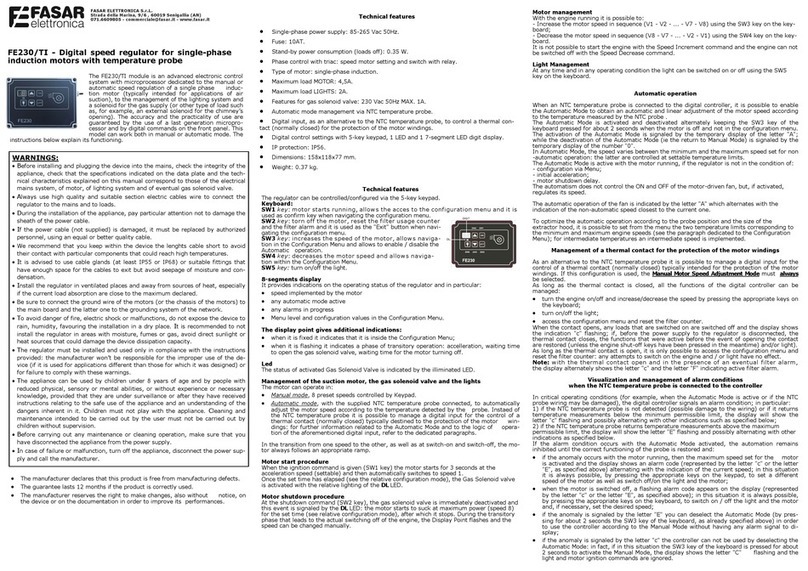
The FE230/T module is an advanced electronic control
system with microprocessor dedicated to the manual
or automatic speed regulation of a single phase
induction motor (typically intended for applications of
air suction), to the management of the lighting system
and a solenoid for the gas supply (or other type of
load such as, for example, an external solenoid for the
chimney’s opening). The accuracy and the practicality of use are guaranteed by
the use of a last generation microprocessor and by digital commands on the
front panel. This model can work both in manual or automatic mode. The in-
structions below explain its functioning.
Technical features
Single-phase power supply: 85-265 Vac 50Hz.
Fuse: 10AT.
Stand-by power consumption (loads off): 0.35 W.
Phase control with triac: speed motor setting and switch with relay.
Type of motor: single-phase induction.
Maximum load MOTOR: 4,5A.
Maximum load LIGHTS: 2A.
Features for gas solenoid valve: 230 Vac 50Hz MAX. 1A.
Automatic mode management via NTC temperature probe.
Digital input, as an alternative to the NTC temperature probe, to control a thermal con-
tact (normally closed) for the protection of the motor windings.
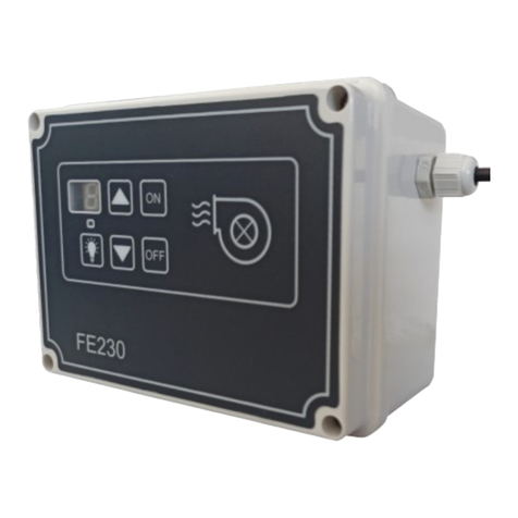
Digital control settings with 5-key keypad, 1 LED and 1 7-segment LED digit display.
IP protection: IP56.
Dimensions: 158x118x77 mm.
Weight: 0.37 kg.
Technical features
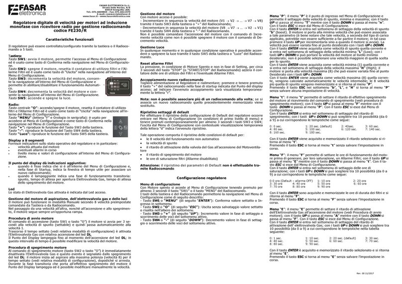
The regulator can be controlled/configured via the 5-key keypad.
Keyboard:
SW1 key: motor starts running, allow s the acces to the configuration menu and it is
used as confirm key when navigating the configuration menu.
SW2 key: torn off the motor, reset the filter usage counter
and the filter alarm and it is used as the "Exit" button when navi-
gating the configuration menu.
SW3 key: increases the speed of the motor, allow s naviga-
tion in the Configuration Menu and allows to enable / disable the
Automatic operation.
SW4 key: decreases the motor speed and allow s naviga-
tion within the Configuration Menu.
SW5 key: turn on/off the light.
8-segments display
It provides indications on the operating status of the regulator and in particular:
speed implemented by the motor
any automatic mode active
any alarms in progress
Menu level and configuration values in the Configuration Menu.
The display point gives additional indications:
when it is fixed it indicates that it is inside the Configuration Menu;
when it is flashing it indicates a phase of transitory operation: accelleration, waiting time
to open the gas solenoid valve, waiting time for the motor turning off.
Led
The status of activated Gas Solenoid Valve is indicated by the illiminated LED.
Management of the suction motor, the gas solenoid valve and the lights
The motor can operate in:
Manual mode, 8 preset speeds controlled by Keypad.
Automatic mode, with the supplied NTC temperature probe connected, to automatically
adjust the motor speed according to the temperature detected by the probe. Instaed of
the NTC temperature probe it is possible to manage a digital input for the control of a
thermal contact (normally closed) typically destined to the protection of the motor win-
dings: for further information related to the Automatic Mode and to the logic of opera-
tion of the aforementioned digital input, refer to the dedicated paragraphs.
In the transition from one speed to the other, as well as at switch-on and switch-off, the mo-
tor always follows an appropriate ramp.
Motor start procedure
When the ignition command is given (SW1 key) the motor starts for 3 seconds at the
acceleration speed (settable) and then automatically switches to speed 1.
Once the set time has elapsed (see the relative configuration mode), the Gas Solenoid valve
is activated with the relative lighting of the DL LED.
Motor shutdown procedure
At the shutdown command (SW2 key), the gas solenoid valve is immediately deactivated and
this event is signaled by the DL LED: the motor starts to suck at maximum power (speed 8)
for the set time (see relative configuration mode), after which it stops. During the transitory
phase that leads to the actual switching off of the engine, the Display Point flashes and the
speed can be changed manually.
Motor management
With the engine running it is possible to:
- Increase the motor speed in sequence (V1 - V2 - ... - V7 - V8) using the SW3 key on the key-
board;
- Decrease the motor speed in sequence (V8 - V7 - ... - V2 - V1) using the SW4 key on the key-
board.
It is not possible to start the engine with the Speed Increment command and the engine can not
be switched off with the Speed Decrease command.
Light Management
At any time and in any operating condition the light can be switched on or off using the SW5
key on the keyboard.
Automatic operation
When an NTC temperature probe is connected to the digital controller, it is possible to enable
the Automatic Mode to obtain an automatic and linear adjustment of the motor speed according
to the temperature measured by the NTC probe .
The Automatic Mode is activated and deactivated alternately keeping the SW3 key of the
keyboard pressed for about 2 seconds when the motor is off and not in the configuration menu.
The activation of the Automatic Mode is signaled by the temporary display of the letter "A";
while the deactivation of the Automatic Mode (ie the return to Manual Mode) is signaled by the
temporary display of the number "0".
In Automatic Mode, the speed varies between the minimum and the maximum speed set for non
-automatic operation: the latter are controlled at settable temperature limits.
The Automatic Mode is active with the motor running, if the regulator is not in the condition of:
- configuration via Menu;
- initial acceleration;
- motor shutdown delay.
The automatism does not control the ON and OFF of the motor-driven fan, but, if activated,
regulates its speed.
The automatic operation of the fan is indicated by the letter "A" which alternates with the
indication of the non-automatic speed closest to the current one.
To optimize the automatic operation according to the probe position and the size of the
extractor hood, it is possible to set from the menu the two temperature limits corresponding to
the minimum and maximum engine speeds (see the paragraph dedicated to the Configuration
Menu); for intermediate temperatures an intermediate speed is implemented.
Management of a thermal contact for the protection of the motor windings
As an alternative to the NTC temperature probe it is possible to manage a digital input for the
control of a thermal contact (normally closed) typically intended for the protection of the motor
windings. If this configuration is used, the Manual Motor Speed Adjustment Mode must always
be selected.
As long as the thermal contact is closed, all the functions of the digital controller can be
managed:
turn the engine on/off and increase/decrease the speed by pressing the appropriate keys on
the keyboard;
turn on/off the light;
access the configuration menu and reset the filter counter.
When the contact opens, any loads that are switched on are switched off and the display shows
the indication "c" flashing; if, before the power supply to the regulator is disconnected, the
thermal contact closes, the functions that were active before the event of opening the contact
are restored (unless the engine shut-off keys have been pressed in the meantime) and/or light).
As long as the thermal contact is open, it is only possible to access the configuration menu and
reset the filter counter: any attempts to switch on the engine and / or light have no effect.
Note: w ith the thermal contact open and in the presence of an eventual filter alarm,
the display alternately shows the letter "c" and the letter "F" indicating active filter alarm.
Visualization and management of alarm conditions
when the NTC temperature probe is connected to the controller
In critical operating conditions (for example, when the Automatic Mode is active or if the NTC
probe wiring may be damaged), the digital controller signals an alarm condition; in particular:
1) if the NTC temperature probe is not detected (possible damage to the wiring) or if it returns
temperature measurements below the minimum permissible limit, the display will show the
letter "c" flashing and possibly alternating with other indications such as specified below;
2) if the NTC temperature probe returns temperature measurements above the maximum
permissible limit, the display will show the letter "E" flashing and possibly alternating with other
indications as specified below.
If the alarm condition occurs with the Automatic Mode activated, the automation remains
inhibited until the correct functioning of the probe is restored and:
if the anomaly occurs with the motor running, then the maximum speed set for the motor
is activated and the display shows an alarm code (represented by the letter "c" or the letter
"E", as specified above) alternating with the indication of the current speed; in this situation
it is always possible, by pressing the appropriate keys on the keypad, to set a different
speed of the motor as well as switch off/on the light and the motor;
when the motor is switched off, a flashing alarm code appears on the display (represented
by the letter "c" or the letter "E", as specified above); in this situation it is always possible,
by pressing the appropriate keys on the keyboard, to switch on / off the light and the motor
and, if necessary, set the desired speed;
if the anomaly is signaled by the letter "E" you can deselect the Automatic Mode (by pres-
sing for about 2 seconds the SW3 key of the keyboard, as already specified above) in order
to use the controller according to the Manual Mode without having any alarm signal to di-
splay;
if the anomaly is signaled by the letter "c" the controller can not be used by deselecting the
Automatic Mode: in fact, if in this situation the SW3 key of the keyboard is pressed for about
2 seconds to activate the Manual Mode, the display shows the letter "C" flashing and the
light and motor ignition commands are ignored.
The manufacturer declares that this product is free from manufacturing defects.
The guarantee lasts 12 months if the product is correctly used.
The manufacturer reserves the right to make changes, also without notice, on
the device or on the documentation in order to improve its performances.
WARNINGS:
Before installing and plugging the device into the mains, check the integrity of the
appliance, check that the specifications indicated on the data plate and the tech-
nical characteristics explained on this manual correspond to those of the electrical
mains system, of motor, of lighting system and of eventual gas solenoid valve.
Always use high quality and suitable section electric cables wire to connect the
regulator to the mains and to loads.
During the installation of the appliance, pay particular attention not to damage the
sheath of the power cable.
If the power cable (not supplied) is damaged, it must be replaced by authorized
personnel, using an equal or better quality cable.
We recommend that you keep within the device the lenghts cable short to avoid
their contact with particular components that could reach high temperatures.
It is advised to use cable glands (at least IP55 or IP68) or suitable fittings that
have enough space for the cables to exit but avoid seepage of moisture and con-
densation.
Install the regulator in ventilated places and away from sources of heat, especially
if the current load absorption are close to the maximum declared.
Be sure to connect the ground wire of the motors (or the chassis of the motors) to
the main board and the latter one to the grounding system of the network.
To avoid danger of fire, electric shock or malfunctions, do not expose the device to
rain, humidity, favouring the installation in a dry place. It is recommended to not
install the regulator in areas with moisture, fumes or gas, avoid direct sunlight or
heat sources that could damage the device dissipation capacity.
The regulator must be installed and used only in compliance with the instructions
provided: the manufacturer won’t be responsible for the improper use of the de-
vice (if it is used for applications different than those for which it was designed) or
for failure to comply with these warnings.
The appliance can be used by children under 8 years of age and by people with
reduced physical, sensory or mental abilities, or without experience or necessary
knowledge, provided that they are under surveillance or after they have received
instructions relating to the safe use of the appliance and an understanding of the
dangers inherent in it. Children must not play with the appliance. Cleaning and
maintenance intended to be carried out by the user must not be carried out by
children without supervision.
Before carrying out any maintenance or cleaning operation, make sure that you
have disconnected the appliance from the power supply.
In case of failure or malfunction, turn off the appliance, disconnect the power sup-
ply and call the manufacturer.


