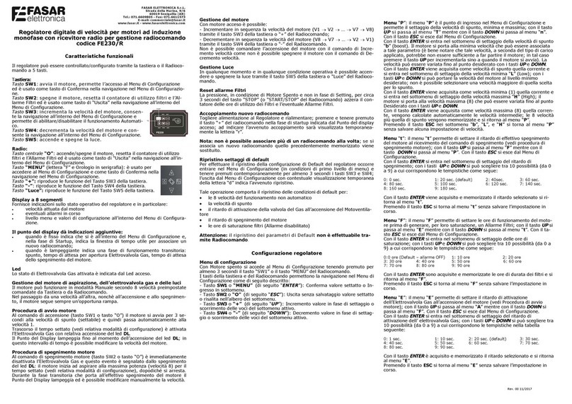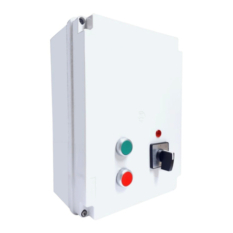
I nostri regolatori digitali ad autotrasformatore consentono di variare la
velocità di un motore a induzione monofase a 2 fili (tipicamente destinato
ad applicazioni di aspirazione dell’aria) in modo semplice e pratico utilizzan-
do la tastiera posta sul pannello frontale del dispositivo.
DESIGN PRATICO E DI FACILE PULIZIA.
Rev. 00 11/2021
AVVERTENZE:
Prima di installare ed alimentare il prodotto, assicurarsi dell’integrità dell’apparecchio e verificare che i dati di targa e le caratteri-
stiche tecniche riportate sul presente manuale siano coerenti con le caratteristiche della rete elettrica di alimentazione, del motore
utilizzato e del carico ausiliario.
Utilizzare sempre cavi elettrici di qualità e sezione adeguata per il collegamento del regolatore alla rete di alimentazione e ai cari-
chi.
Durante l’installazione dell’apparecchio, prestare particolare attenzione a non danneggiare la guaina del cavo di alimentazione.
Se il cavo di alimentazione è danneggiato, esso deve essere sostituito da personale autorizzato, usando un cavo di qualità pari o
superiore.
Si consiglia di mantenere all’interno del dispositivo le lunghezze dei cavi corte per evitare il loro contatto con particolari compo-
nenti che potrebbero raggiungere temperature elevate.
Installare il regolatore in luoghi ventilati e lontano da fonti di calore soprattutto se le correnti di assorbimento dei carichi si avvici-
nano a quelle massime dichiarate.
Avere cura di collegare il filo di terra del motore (o lo chassis del motore stesso) alla scheda e quest’ultima all’impianto di terra
della rete.
Per evitare il pericolo di incendi, di scosse elettriche o di malfunzionamenti in genere, non esporre l’apparecchio alla pioggia, all’u-
midità, privilegiando l’installazione in luoghi asciutti. Si raccomanda di non installare il regolatore in zone esposte alla condensa, a
vapori o gas, evitando la radiazione solare diretta o fonti di calore che potrebbero compromettere la capacità di dissipazione in
potenza del dispositivo.
Il regolatore deve essere installato ed utilizzato solo conformemente alle modalità operative previste: il costruttore non si assume
alcuna responsabilità in caso di utilizzo improprio del dispositivo (utilizzo dell’apparecchio per applicazioni diverse da quelle per cui
è stato progettato) o in caso di inosservanza delle presenti avvertenze.
L’apparecchio può essere utilizzato da bambini di età non inferiore a 8 anni e da persone con ridotte capacità fisiche, sensoriali o
mentali, o prive di esperienza o della necessaria conoscenza, purchè sotto sorveglianza oppure dopo che le stesse abbiano ricevu-
to istruzioni relative all’uso sicuro dell’apparecchio e alla comprensione dei pericoli ad esso inerenti. I bambini non devono giocare
con l’apparecchio. La pulizia e la manutenzione destinata ad essere effettuata dall’utilizzatore non deve essere effettuata da bam-
bini senza sorveglianza.
Prima di effettuare qualsiasi operazione di manutenzione o di pulizia, assicurarsi di aver scollegato l’apparecchio dalla rete di
alimentazione.
In caso di guasto o di mal funzionamento, spegnere l’apparecchio, scollegare la rete di alimentazione e chiamare il costruttore.
Regolatori di velocità digitale ad autotrasformatore a 5 velocità
cod. FE1055-FE1056-FE1057-FE1058
Il costruttore dichiara che il prodotto è esente da difetti di fabbricazione.
La garanzia ha la durata di 12 mesi purché il prodotto sia usato correttamente.
Il costruttore si riserva di apportare modifiche, anche senza preavviso, sulla macchina o sulla documentazione associata allo
scopo di migliorarne le prestazioni.
Fig.1 Schema delle connessio ni
FE1055 - 3A
FE1056 - 5A
FE1057 - 7,5A
FE1058 - 10A
FASAR ELETTRONICA S.r.L
Strada della Marina 9/6, 60019 Senigallia (AN) - 071.6609805 -
commerciale@fasar.it- www.fasar.it
Codice FE1055 FE1056 FE1057 FE1058
Alimentazione Monofase
220-240Vac -50/60Hz
Monofase
220-240Vac -50/60Hz
Monofase
220-240Vac - 50/60Hz
Monofase
85-265Vac - 50Hz
Corrente MAX
assorbimento MOTORE 3 A 5 A 7,5 A 10 A
Carico ausiliario
(ad esempio elettrovalvola) 3A 3A 3A 3A
Dimensioni in mm 240x190x160h 240x190x160h 300x220x120h 300x220x120h
Grado di protezione IP56 IP56 IP56 IP56
Ingresso contatto termico Tipo NC Tipo NC Tipo NC Tipo NC
INSTALLAZIONE DEL REGOLATORE
Dopo aver rimosso il coperchio, praticare sulla scatola i fori necessari di diametro adeguato al passaggio dei cavi. Al termine
dell’operazione non devono essere presenti sbavature, ammaccature o simili che possano pregiudicare il grado di protezione
dell’involucro. Fissare quindi la scatola al supporto desiderato tramite viti di fissaggio adeguate ed effettuare i collegamenti alla
morsettiera rispettando lo schema delle connessioni (Fig.1).
Fornita l’alimentazione al motore, si accende il led rosso in corrispondenza del tasto OFF: il motore è alimentato ma spento.
L’accensione del motore avviene premendo un tasto qualsiasi tra 1-2-3-4 e 5: il led verde associato al tasto si accende e il led
rosso (OFF) si spegne.
Dopo circa mezzo secondo dall’accensione del motore, si attiva anche l’elettrovalvola del gas (o qualsiasi altro carico collegato) e
si accende il led giallo (AUX).
Se il motore è alla velocità 5, premendo per 3 secondi il tasto corrispondente, si attiva la velocità intensiva per 10 minuti, il led
corrispondente lampeggia. Trascorso questo tempo, il motore si spegne automaticamente (led verde corrispondente si spegne, led
giallo Aux si spegne, led rosso si accende).
Con motore ON ad una qualsiasi velocità, tenendo premuto per 3 secondi il tasto corrispondente alla velocità 5, si attiva la velocità
intensiva per 10 minuti (led corrispondente lampeggia). Trascorso questo tempo, il motore ritorna automaticamente alla velocità
precedentemente impostata.
Durante questo intervallo di tempo, è sempre possibile uscire dalla funzione di velocità intensiva premendo un qualsiasi tasto tra
1-2-3-4-5 e OFF, il motore va alla velocità selezionata o si spegne.
Per spegnere il motore, premere il tasto dedicato (OFF), l’elettrovalvola del gas (o altro carico) si disattiva e il led giallo si spegne,
il led verde corrispondente all’ultima velocità si spegne e si accende il led rosso.
Il contatto termico del motore è normalmente chiuso. Quando c’è un surriscaldamento degli avvolgimenti del motore, il contatto si
apre, il motore e l’elettrovalvola (o altro carico) si spengono: i led verdi e rosso lampeggiano per segnalare la presenza dell’allar-
me, i tasti non funzionano. La segnalazione di allarme rimane finchè il contatto termico non si chiude e non interviene l’utente.
Durante la segnalazione di allarme (led lampeggianti), l’utente può:
Premere un qualsiasi tasto, i led continuano a lampeggiare e non c’è nessun cambiamento: il contatto termico è ancora
aperto e l’allarme è ancora presente.
Premere il tasto OFF: i led non lampeggiano più e si accende il led rosso (OFF), il motore è spento ma alimentato, il contat-
to termico è chiuso, l’allarme è rientrato.
Premere un qualsiasi tasto tra 1 e 5: i led non lampeggiano più e si accende il led verde corrispondente alla velocità corri-
spondente, il motore riprende a girare alla velocità desiderata, il contatto termico è chiuso, l’allarme è rientrato.

