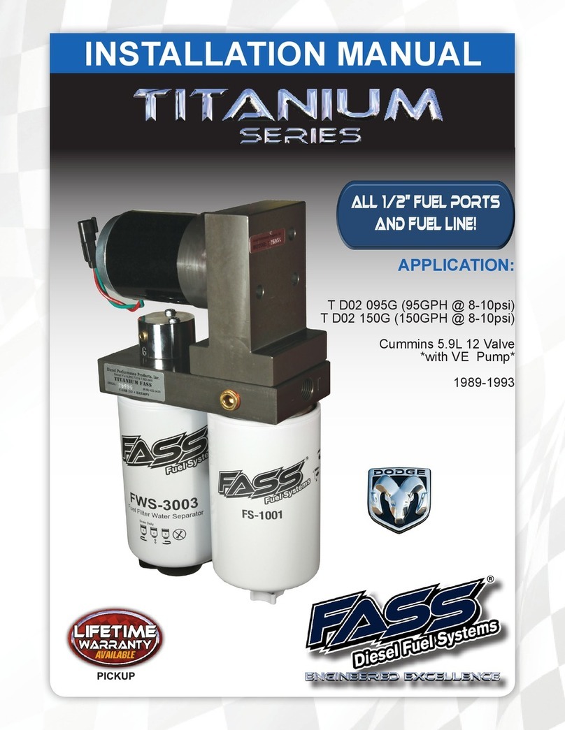
Fass Titanium Series User manual

T
S
-
C08
-100G
(100GPH @ 5-7PSI)
TS-C08-165G
(165GPH @ 5-7 PSI)
FASS DIESEL FUEL SYSTEMS® / ENGINEERED EXCELLENCE
GM 6.5L TURBO DIESEL
Standard Pickup Truck
1992-2000
*NOTE: CAB AND CHASSIS MAY
REQUIRE MODIFICATIONS
APPLICATION:
TITANIUM SERIES
INSTALLATION MANUAL
ALL 1/2” FUEL PORTS
LIFETIME
WARRANTY
A
V
AILABLE

For more information,
contact Technical Support:
Diesel Performance Products, Inc.
16240 State Hwy O. Suite B
Marthasville, MO 63357
636-433-5410
www.fassride.com
(866) 769.3747
Thank you for cho
osing FASS, from
Diesel Performance Products, Inc.
FASS specializes in building extremely high-quality fuel products. We have earned an
unsurpassed reputation for excellence in our industry by using only the highest-quality
American-made components. In order to support our American workers and our American
economy, more than 98+ percent of our products are manufactured completely in the United
States.
Of course, that dedication to excellence comes at a price, but it is important to remember
that price does not dictate quality-quality dictates price! We will never compromise by using
cheaper, foreign-made components, like so many of our competitors do.
Customer satisfaction is our top priority and we strive always to provide outstanding customer
service. Our Research and Development department, in conjunction with our Dealer Support
Department, continually searches for ways to improve quality, expand our product line, and
provide superb support. Our exclusive ViP Network ensures that customers receive the
proper products and support at the local level. The extended lifetime warranty is only
available on products purchased from the network. There is no warranty on products not
purchased outside the network.
IMPORTANT:
In order to qualify for the lifetime extended warranty, your product registration form and
proof of purchase from an authorized dealer must be submitted to FASS Fuel Systems
within 30 days of purchase. Failure to comply will void the warranty. We have the right to
deny any warranty believed to be false, altered or purchased through an unauthorized or
terminated dealer. Acurrent list of authorized dealers can be found on our website,
FASSRide.com.
The complete conditions of the Limitation of Warranty can be found in the back of this
manual, and FASSRide.com.

www.fassride.com
(866) 769.3747
WARNING!
This product has NO WARRANTY unless:
1. It has been purchased from an Authorized or ViP FASS Dealer. If in doubt,
check www.FASSRide.com. (If your purchase was made on Amazon.com, the
warranty is void. Return the FASS product to the seller and get a refund).
2. It is registered within thirty (30) days of purchase.
Other conditions may apply. Please see full warranty information.
ATTENTION!
Before you begin installation
Register for your Warranty ONLINE at
https://www.fassride.com/register-a-
warranty/
No online access, call our TECH Support at
1-866-769-3747

Your name, address and daytime phone number
Model
(T
S
-
C08-
100G) or (T
S
-
C08
-165G)
Serial Number
Last 6 digits of vehicles’ VIN
Date of purchase
Nature of Your Concern
Serial number
3
2
4
5
6
7
1For best results in accuracy and efficiency
(due to training, communication, and our
relationship with our dealer network), we
recommend a VIP FASS dealer for the
installation. They are prepared to install the
FASS fuel pumps with the most efficiency.
If a situation or problem arises during the
installation, the dealer is prepared to handle
it. Diesel Performance Products, Inc. is not
responsible for any installation mistakes.
If any installation procedure is uncertain, contact FASS technical support.
Call customer service at 636-433-5410,
or send us an e-mail: techsupport@FASSride.com
with the following information:
FOLLOW THESE STEPS
TO ENSURE A SIMPLE, CORRECT
Serial # >
TITANIUM FUEL SYSTEM
INSTALLATION OF YOUR NEW
If you have any questions or concerns that
cannot be addressed with your dealer,
email or call FASS.
The installation recommendations contained
herein are guidelines. Use good judgment
and take into consideration your vehicles’
accessories.
Inventory the package components. Notify
the place of purchase immediately of any
parts missing or damaged.
Be sure to identify the proper FASS System and fuel line
configuration. For help, our product finder can be found at
www.FASSride.com. Follow the instructions to see fuel line detail.
Read all instructions before starting
installation of this product.
Pay close attention to ALL WARNINGS
Be sure the serial number on this installation
manual matches that on the outside of the
box.
ATTENTION:
www.fassride.com
(866) 769.3747

Recommended Application
TS-C08-100G
6.5 Turbo Diesel 1992-2000 with stock-600 horsepower.
TS-C08-165G
6.5 Turbo Diesel 1992-2000 with 600-1,000 horsepower.
www.fassride.com
(866) 769.3747
INSTALLATI
ON MANUAL
TS-C08-100G OR
TS-C08-165G
1. Read all instructions before starting installation of this product!
2. Installing the improper FASS Pump can cause severe engine damage.
3. Secure vehicle from ROLLING!
4. Cab and Chassis may require modifications
5. Consult vehicle’s manufacturers’ instructions concerning the electrical
system before attempting any electrical connections.
6. Be sure that the serial # on this installation manual matches that of the
outside of the box.
7. Flush and clean all brass fittings and fuel line from debris.
8. Keep debris from entering the internals of the system during
installation. Getting debris in the water separator nipple can lock up the
motor. If the motor does lock up from debris call FASS for technical
assistance.
9. Wear safety glasses when operating power tools such as drills and
grinders or when using a punch or chisel.
10. Properly secure lines to prevent chaffing.

www.fassride.com
(866) 769.3747
WARNING!
Always be sure to fill the fuel tank to full after a new
FASS installation. Failure to do so can result in excessive
sound output, or priming issues!

wwwwww..ffassrassriidde.e.cocomm
((866)866) 769.769.37473747
TITANIUM
SIGNATURE SERIES
100 GPH or 165 GPH
5-7psi (Approximately)
PUMPPUMP GGUIDE:UIDE:
1. 1. "E" To"E" To E Enginengine
2.2.
“R" Return to Tank“R" Return to Tank
3. 3. "H" Coolant Heater Ports"H" Coolant Heater Ports
4. 4. Serial Number Serial Number
5. 5. “T" Fuel Inlet“T" Fuel Inlet
6. 6. Electric Heater Ports Electric Heater Ports
7. 7. "G" Gauge Port"G" Gauge Port
1.1.
2.2.
3.3.
4.4.
5.5.
6.6.
7.7.
IINNSSTTAALLLLAATTIIOON N GUIDE: GUIDE:
StepStep 1.1. Install Electrical HarnessInstall Electrical Harness
StepStep 2.2.
Remove the fuel tank
Step 3.Step 3. Prepare the FASS
Step 4.4. Mount the FASS
Step 5. Install Fuel Line
Step 6. Review
FFrronont Vt Viewiew
RRear Vear Viewiew

www.fassride.com
(866) 769.3747
TITANIUM
SIGNATURE SERIES
100 GPH or 165 GPH
5-7 PSI
(Ap
proximately)
Note: Going over 30 PSI WILL void warranty.
NOTE: WARRANTY MAY BE
VOID IF
SILICONE
BAND IS REMOVED FROM MOTOR!!
The silicone band is in place to retain motor
wires, preventing damage to the electric motor.

CONTENTS
NOTE: Owner’s Manual available for download on our website,
www.FASSride.com
MP-9085
www.fassride.com
(866) 769.3747
WH-1006-3 FL-1001x14' PBR-2001PBF-2002-SHORT
RS-2002
DIELECTRIC GREASE
OR-030
TWO (2)
OR-017
NOTE: THESE SPARE BASE O-RINGS ARE INCLUDED
WITH THE KIT IN THE EVENT OF A PINCHED O-RING
DURING ASSEMBLY
RELAY COVER
FL-1002x9' PFB-2001C-SHORT

MOUNTING
PACKAGE
CONTENTS
www.fassride.com
(866) 769.3747
(1)- 10-301
FOUR (4) Hex Bolt 3/8”
-16x 1 1/2”
TWO (2) RING TERMINALS
FOUR (4) LOCKING
NUT 3/8""
FOUR (4) 3/8" WASHERS
TWO (2) PL-1005
(1)-10-300
CABLE TIES
TWO (2)-PL-1004
(1) FUEL SUCTION TUBE
(3) WA-2001
(1)- BHF-1002
(1) - 46405
(1)- 47003
(1) PL-1002
(2)3/8 HOSE CLAMPS
(1)0790750
(1) RS-2001C-SHORT
(1) RS-2004
(1) CTMC-1001
(3) Hex Bolt .25-20x1

STEP 1:
INSTALL ELECTRICAL HARNESS
www.fassride.com
(866) 769.3747
The installation of the electrical harness is done first, allowing power to be applied to the
pump for lubrication purposes later in the installation.
NOTE: USE SUPPLIED DIELECTRIC GREASE
SPARINGLY ON ALL ELECTRICAL
CONNECTIONS!
BE SURE TO GREASE RELAY
PIGTAIL!

STEP 1:
INSTALL ELECTRICAL HARNESS
www.fassride.com
(866) 769.3747
The installation of the electrical harness is done first, allowing power to be applied to the
pump for lubrication purposes later in the installation.
Install the Relay Cover onto the relay on the
FASS harness.

STEP 1:
INSTALL ELECTRICAL HARNESS
www.fassride.com
(866) 769.3747
The installation of the electrical harness is done first, allowing power to be applied to the
pump for lubrication purposes later in the installation.
NOTE: BE SURE TO INSTALL THE SUPPLIED
10 AMP FUSE INTO THE FASS WIRING
HARNESS!!

STEP 1:
INSTALL ELECTRICAL HARNESS
The installation of the electrical harness should be completed
first. This will allow power to be applied to the pump during
installation.
www.fassride.com
(866) 769.3747
A. Using wire stripping tool remove excess insulation off the add-a-fuse and the
WH-1006-3
B. Place wire from 46405 and single red bare wire from WH-1006-3 into
butt connector. Using crimping tool connect 46405 and WH-1006-3 with
butt connector. Install 47003 to 46405 top slot (opening that is near the
spade).
C. Crimp the ring terminals to the red and green wires of the WH-1006-3 Wire
Harness. Attach red wire to the positive terminal of the battery and the green
terminal to the negative terminal. The use of a corrosion preventative on
electrical connections is recommended.

www.fassride.com
(866) 769.3747
STEP 1:
INSTALL ELECTRICAL HARNESS
D. Secure relay and fuse in an upright position, as shown, to prevent moisture from
entering. Di-electric grease may be applied to prevent corrosion.
RELAY
FUS
E. Locate the fuse panel on the kick panel of the dash. Route the single red wire of the FASS harness
through the firewall and to the fuse panel.
F. Using a test light, locate a key-on fuse in the fuse panel. Once you have located a key-on fuse cavity, install
the existing fuse in the lower fuse location on the 46405 add-a-circuit. Install the 46405 into the selected
cavity.
Note: The supplied
3amp fuse in the
top fuse cavity!
The OEM fuse is to
go in the bottom
cavity!

www.fassride.com
(866) 769.3747
STEP 1:
INSTALL ELECTRICAL HARNESS
F.Route WH-1006-3 wire harness along frame rail to mounting location of pump. Completion of this
step will be addressed in the Mounting Step 3.

STEP 2:
Remove Fuel Tank
www.fassride.com
(866) 769.3747
Some of the photo’s are of a different application, procedures are the same..
A. Loosen both fuel tank fill and fuel tank vent clamps. (A small amount of penetrating oil can
be helpful to remove these older dry connections) Remove both rubber hoses. (Save)
B. Disconnect the factory fuel pump supply line and the factory return line. Then unplug the fuel
level sensor.
C. Using a transmission jack or other jack, securely remove the fuel tank. Once the tank is secure,
remove the fuel tank straps and lower the tank.
(Near empty fuel tanks are simpler to remove, if your tank is full or near full a second hand is
useful or the aid of small ratchet straps. Fuel will slosh back and forth making the tank unstable.)
Fuel tank
strap bolt.

www.fassride.com
(866) 769.3747
STEP 3:
PREPARE
SUCTION AND RETURN LINES
A. Once the fuel tank is removed, remove the factory fuel tank sending unit. Rotate the
locking ring that fastens the fuel tank sending unit to the fuel tank, counter clockwise. This
will allow you to remove the fuel tank sending unit. (Take note as to how the fuel lines are
routed in the factory location.)With the fuel tank sending unit removed, install the
CTMC-1001 on the factory fuel supply line. Then set the sending unit aside at this time.
DO NOT MODIFY THE SENDING UNIT.
DRIVE SHAFT SIDE
FILL NECK SIDE FRONT OF TRUCK
FILL NECK SIDE
C. Locate the measuring point at the tank, this will be the side of the tank closest to the drive shaft.
(Opposite side of the fuel filler neck) Measure over 5 1/2 inches and make a mark. (As seen in figure
2-A)
D. Locate the front side of the tank, this will be the side facing the front of the truck. Measure out 2
3/4 inches from the fuel tank sending unit hole. (As seen in figure 2-B)
2-B
Factory Supply line
CTMC-1001
Injection
pump return
NOTE! Insure the o-ring on the factory fuel supply line is in good condition, this may
need replaced to acquire a good seal.
2-A
O-ring

www.fassride.com
(866) 769.3747
STEP 3 : PREPARE
SUCTION AND RETURN
LINES
E. Once you have marked the location of the suction bulk head (BHF-1002)
use a center punch and make a mark in the fuel tank. Then proceed to drill
a 1 3/8" hole, using a hole saw.
F. Now that the hole has been established, using a de-buring tool clean the edges of the
new hole to insure a quality sealing surface.(Note the fuel tank is steel and may have
sharp edges, gloves may be necessary.)

www.fassride.com
(866) 769.3747
STEP 3:
PREPARE SUCTION AND
RETURN LINES
G. Prepare the BHF-1002 by installing the PL-1004 fittings to both sides of the BHF-1002. Then
install the ST-1005XP to the suction nipple of the BHF-1002. Fasten the 3/8's hose clamp around
the suction nipple and the ST-1005P. (See section 3-A and 3-B for further instruction)
NOTE: Hose clamps are not recommended for push lock fittings. They will hold up to 300 psi! Use
oil on fittings and inside fuel line when installing push lock fittings.
Lube Lock Tab
Other manuals for Titanium Series
4
Table of contents
Other Fass Water Filtration System manuals
Popular Water Filtration System manuals by other brands

Ecosoft
Ecosoft AquaPoint FPV24520ECO user manual

deconta
deconta C 25 L operating instructions

Power Fist
Power Fist 8787681 user manual

MSR
MSR MINIWORKS EX instruction manual

Sentera Controls
Sentera Controls FIMX8 Mounting and operating instructions

UV Dynamics
UV Dynamics UVD400 Installation and maintenance manual