Fassi F 170A.23 User guide

1
FASSI CRANE
F 170A.23
use and maintenance
FROM SERIAL NUMBER *3001*
INDEX OF PARAGRAPHS
A0 INTRODUCTION
B0 SAFETY NORMS
C0 WARNING AND INSTRUCTIONS
C0.1 Before operating
C0.2 During operation
C0.3 At the end of the operation (Prior to driving the vehicle)
D0 CLASSIFICATION OF THE CRANE MODEL
D0.1 Technical data
D1 IDENTIFICATION OF THE CRANE MODEL
D1.1 Crane mark
D1.2 Crane mark
E0 CRANE NOMENCLATURE
E0.1 Crane with ground controls and (on request) Crane with ground controls
and with top seat controls by hand cables
E0.2 Crane with top seat controls and with ground controls for outriggers
F0 NOMENCLATURE OF THE SAFETY AND PROTECTION DEVICES
F0.1 Crane with ground controls and (on request) Crane with ground controls
and with top seat controls by hand cables
F0.2 Crane with top seat controls and with ground controls for outriggers
F1 NOMENCLATURE OF THE SAFETY AND PROTECTION DEVICES
F1.1 Crane with ground controls and (on request) Crane with ground controls
and with top seat controls by hand cables
F1.2 Crane with top seat controls and with ground controls for outriggers
G0 SUPPLEMENTARY BEAMS
G0.1 Identification of the supplementary beams
G1 TILTABLE OUTRIGGER RAMS
G2 MANOEUVRES AND CONTROLS TO STABILIZE THE VEHICLE
G2.1 Supplementary beam; manual extension of the outrigger supports
G2.2 Functions of control levers for stabilization
G2.3 Controls to stabilize the vehicle
G2.4 Bilateral controls to stabilize the vehicle
H0 CONTROLS TO OPERATE THE CRANE
H0.1 Manoeuvres to unfold the crane into a working condition
H0.2 Manoeuvres to fold the crane into the rest condition
Edition 25.09.2000

H0.3 Manoeuvres to unfold the crane "C" into a working condition
H0.4 Manoeuvres to fold the crane "C" into the rest condition
H1 MANOEUVRES OF THE CRANE LOADS
H1.1 Lifting moment limiting device “intelligent type”
H1.2 Lifting moment limiting device for two working sectors (optional)
H1.3 Control panels
H1.4 Reactivation button of crane functions with standard distributor in the
absence of the electric power
H1.5 Emergency exclusion screw of the lifting moment limiting device
(crane with standard distributor)
H1.6 Emergency tap lever of the lifting moment limiting device
(crane with Danfoss distributor)
H1.7 Rotation limiting device
H2 MANOEUVRES OF THE CRANE LOADS
H2.1 Load limiting device
H2.2 Lifting moment limiting device “intelligent type” (optional)
H2.3 Reactivation button of crane functions with standard distributor in the
absence of the electric power
H2.4 Emergency exclusion screw of the lifting moment limiting device
(crane with standard distributor)
H2.5 Emergency tap lever of the lifting moment limiting device
(crane with Danfoss distributor)
L0 USE OF IMPLEMENTS
L0.1 Hydraulic connections for implements - supplementary hoses
L1 MANUAL EXTENSIONS
L2 CONTROLS TO OPERATE THE HYDRAULIC IMPLEMENTS OF THE CRANE
L3 WINCH
L3.1 Winch for crane
L3.2 Winch for crane
L4 HYDRAULIC JIBS
L4.1 Identification of the hydraulic jib
L4.2 Nomenclature of the hydraulic jib
L4.3 Manoeuvres to unfold the jib in working condition
L4.4 Manoeuvres to fold the jib in rest condition
L4.5 Operations to remove the hydraulic jib from the crane
L4.6 Operations to mount the hydraulic jib on the crane
M0 MAINTENANCE INSTRUCTIONS
M0.1 At the end of every working day
M0.2 After the first 40 hours use
M0.3 After every working week
M0.4 After every 500 working hours
M0.4 Complete overhaul of the crane
N0 TABLE OF HYDRAULIC OIL and lubricants characteristics
P0 POSSIBLE FAULTS
P0.1 Operations which can be carried out by the user
P0.2 Operations to be carried out by a service center
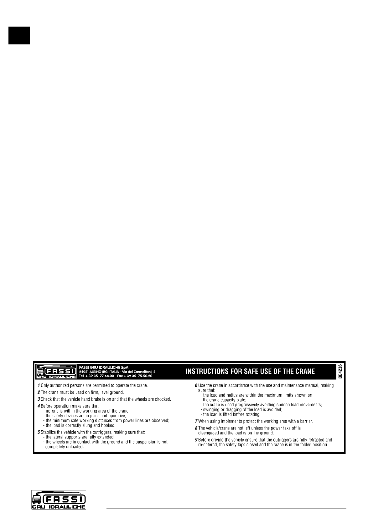
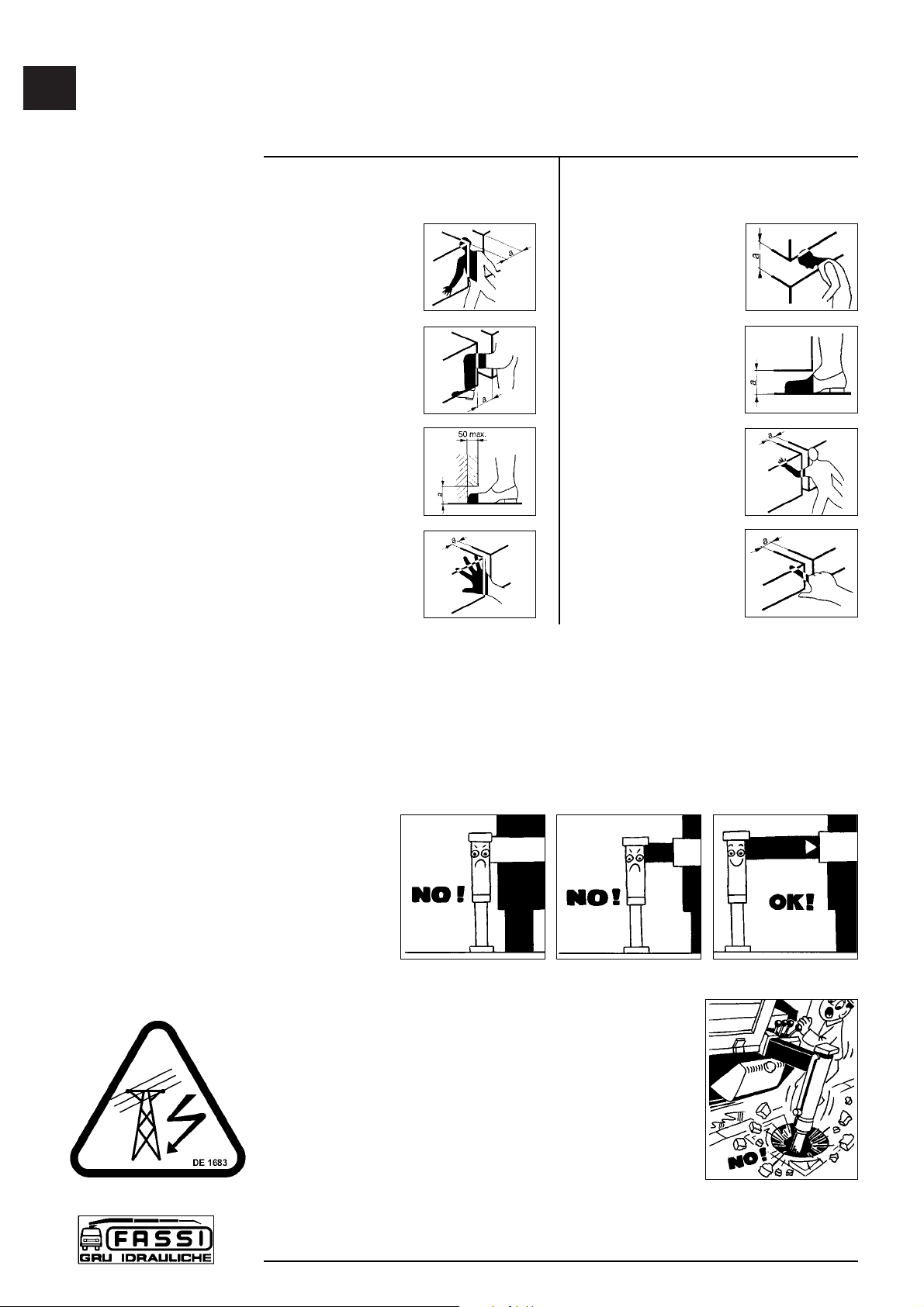
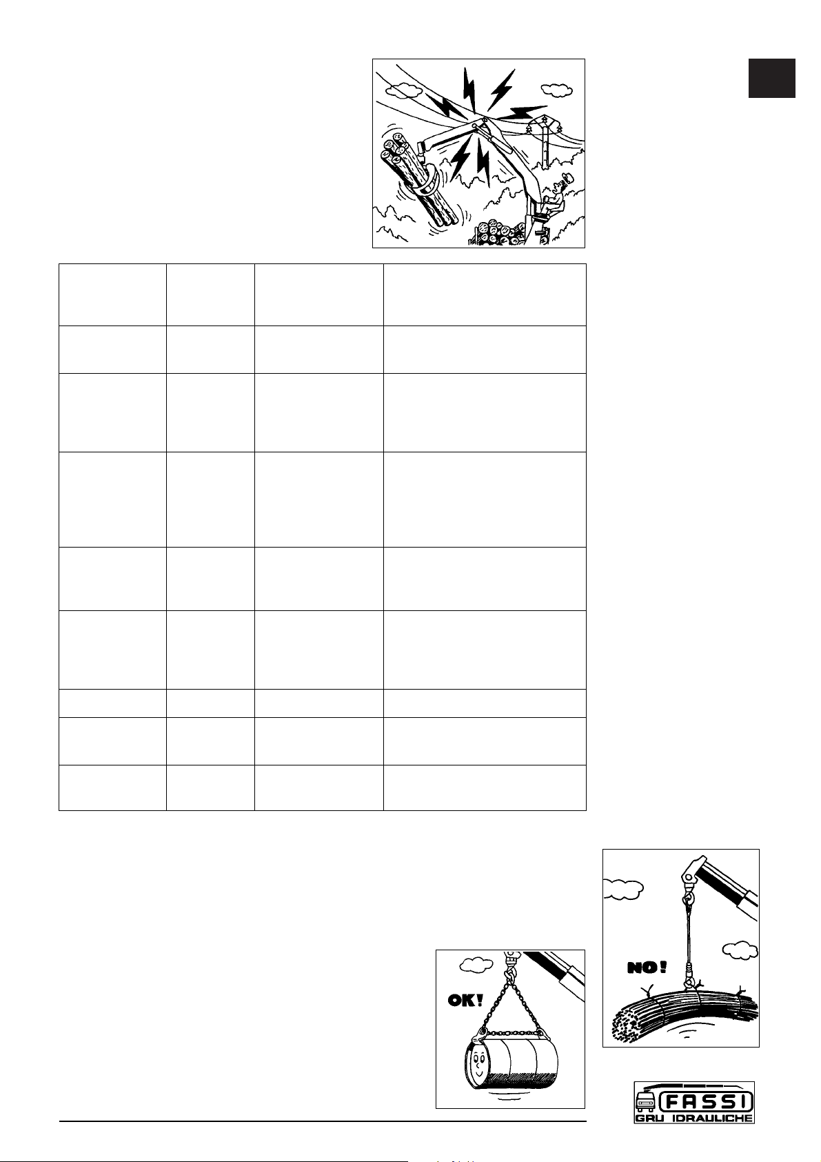
R0 INSTRUCTION AND WARNING PLATES
S0 HYDRAULIC SCHEMATICS FOR CRANE
S1 HYDRAULIC SCHEMATICS FOR CRANE
T0 ELECTRIC SCHEMATICS FOR CRANE
T1 ELECTRIC SCHEMATICS FOR CRANE
V0 CAPACITY PLATES FOR CRANE WITH
LIFTING MOMENT LIMITING DEVICE
V1 CAPACITY PLATES FOR CRANE WITHOUT
LIFTING MOMENT LIMITING DEVICE
2

FASSI CRANE
F 170A.23
use and maintenance
THANK YOU FOR SELECTING ONE OF FASSI CRANES.
This crane is the result of FASSI philosophy: ongoing research, rigorous
testing, data verification, and analysis of performances.
Many years of experience has allowed us to grant you the maximum safety of
operation together with the optimization of machine performances.
All this represents the core of FASSI quality system.
FASSI quality system is in conformity with
UNI EN ISO 9001 - ISO 9001.
The fitment of the crane on the vehicle must be carried out in accordance with
the instructions given by FASSI in the manual for hydraulic crane fitting and
the relevant chassis manufacturers directives.
The Manufacturer declines all responsibility and guarantee if the fitting is
entrusted to workshops without sufficient technical capability to carry out the
work in conformity.
Be sure that the unit has been installed, inspected and tested in accordance
with the local legal requirements.
As well as the principal safety norms, this manual contains a description of the
crane and the instructions for use and maintenance.
The following instructions refer to mobile cranes in general and must be integrated
with the manual for use supplied by the centre responsible for the crane fitting on
truck, vehicle or other type of structure.
READ THIS MANUAL CAREFULLY prior to use or any maintenance. A few minu-
tes spent now could save time and labour later.
Always conform to the safety norms and the instructions for use and maintenance
contained in the present manual in order to guarantee a long life to the crane.
FASSI GRU IDRAULICHE
NOTE
All the paragraphs marked by the symbol refer to components required
within the europen community.
The above-said components may be optional in other countries in accor-
dance with the national regulations in force.
NOTE
The original version of the present manual is in italian.
A0
INTRODUCTION
F 170A.23
3

B0 SAFETY NORMS
Strictly conform to the norms reported by the plates DE4236 (fig. 1) placed
next to the controls, in order to avoid possible accidents while operating the
crane.
Only authorized persons are allowed to operate the crane.
The crane must be used on firm, level ground.
Check that the vehicle hand brake is on and that the wheels are chocked.
Before every operation make sure that:
- no-one is within the working area of the crane;
- the safety devices are in place and operative;
- the minimum safe working distances from power lines are observed;
- the load is correctly slung and hooked.
Stabilize the vehicle by the outrigger rams, making sure that:
- the lateral supports are fully extended;
- the wheels are in contact with the ground and the suspension is not
completely unloaded.
Use the crane in accordance with the use and maintenance manual,
making sure that:
- the load and radius are within the maximum limits shown on the
crane capacity plate;
- the crane is used progressively avoiding sudden load movements
- swinging or dragging of the load is avoided;
- the load is lifted before rotating.
When using implements protect the crane working area with a barrier.
The vehicle/crane are not left unless the power take off is disengaged and the
load is on the ground.
Before driving the vehicle make sure that the outriggers are fully retracted and
re-entered, the safety taps closed and the crane is in folded position.
B0
SAFETY NORMS
F 170A
4
fig. 1

C0 WARNING AND INSTRUCTIONS
The use of the crane is reserved to authorized personnel, instructed in advance,
who has to conform to the safety norms and instructions contained in the use
manual supplied with the crane. (See norms ISO 9926-1)
It is absolutely prohibited to walk or stop under a suspended load
It is prohibited for unauthorized persons to be within the working area.
Under no circumstances interfere with the safety and protection devices.
Warning plates, as well as instruction and operation plates must be replaced
when no longer readable or missing. See Paragraph R0 Instruction and warning
plates.
Do not use the outriggers to raise the vehicle.
To avoid hitting bridges or tunnels check and record the overall height of your
crane in the folded position or in laid position in the body or on the load. Always
respect and pay proper attention to road signs placed in proximity of such
obstacles.
C0.1 Before operating
(!) ATTENTION (!)
Check that protections are in their place and that all safety devices are fitted
and active. (See norms ISO 9927-1)
Keep the ladder and the control station on the top seat, clean; the seat can tilt
forward.
Make sure that control stations are properly lit so as to ensure safety while opera-
ting and allow instruction plates to be visible.
Check that the working area is adequate and pro-
perly lighted for your crane.
Make sure that the hook is always free to rotate on
its pin and that nothing obstructs its vertical positio-
ning.
Check the efficiency of the hook safety catch.
Carefully inspect the condition of ropes or chains.
Make sure that the pallet fork is connected to the crane hook by means of a chain
having at least three (3) rings.
C0.2 During operation
Take the vehicle fumes away from the working area by fitting an extension tube of
a suitable diameter to the exhaust system.
Do not run the engine in a indoor area without first making sure there is adequate
ventilation.
When using the ladder to reach the control station on the top seat, avoid knocking
into the controls while going up or down the ladder.
The control station on the top seat is provided with side safety guards; stay within
these guards.
Make sure that no one is within the working area of the crane.
Avoid swinging the load above working and transit areas; any hidden danger
situation must be audibly alarmed.
C0
WARNING AND
INSTRUCTIONS
F 170A
5

Avoid all those situations which may result in crushing during vehicle stabilization,
crane movement and load handling.
(In conformity with EN 349 standard the minimum safe working distances
to avoid crushing parts of the body)
The table indicates the minimum safety working distances concerning the various
parts of the body.
The figures illustrate circumstances which may turn out to be dangerous if you fail
to respect the minimum safe distances and if it is impossible to introduce larger
parts of the body.
(!) ATTENTION (!)
Failure to respect the minimum safe distances may result in a safety hazard
and a deadly risk.
Remember that
the stability of
the unit (crane-
vehicle) is only
guaranteed by
the complete
lateral extension
of the outriggers
and by the observance of the capacity plates.
Stabilize the vehicle on a horizontal plane with a maxi-
mum tolerance of 1,5 degrees. Make sure that the outrig-
ger rams rest on a solid base, if necessary use larger
outrigger base plates (available on request) to avoid
sinking. If you adopt other means, make sure that they
are suitably sized for the load they must bear.
(!) ATTENTION (!)
Respect the distances di sicurezza from electric
lines; the minimum distance is, according to CEN
norms, five (5) meters, except for otherwise prescribed by national norms.
C0.2
WARNING AND
INSTRUCTIONS
F 170A
6
Parts Minimum safe Figure
of the working
Body distance mm
Body
500
Leg 180
Toes
50
Hand
Wrist
100
Fist
Parts Minimum safe Figure
of the working
Body distance mm
Head
300
Foot
120
Arm
120
Finger
25

(!) ATTENTION (!)
Failure to respect the minimum safe distan-
ces may result in electrical hazards for the
operator and his assistants.
(!) ATTENTION (!)
Do not utilize the crane with wind speed
exceeding 12,5 m\s (value 6 of the Beaufort
scale).
Indications about wind speed
Force of the Wind speed Classification Characteristics
wind m/s
Beaufort scale
0 0,0 - 0,2
Calm
Calm wind, smoke goes up
quite vertically
1 0,3 - 1,5
Light breeze
Smoke reveals the direction
2 1,6 - 3,3 of the wind, one can feel the
wind blowing, leaves start
fluttering.
3 3,4 - 5,4 Moderate breeze Leaves and branches are
4 5,5 - 7,9 in constant motion, small
branches start fluttering.
Dust and papers dance on
the ground.
5 8,0 - 10,7 Fresh breeze Small green branches bend,
the surface of waterways and
lakes are wavy.
6 10,8 - 13,8 Near gale Big branches bend, wind
whistles through high-tension
cables, it's difficult to walk
keeping the umbrella open.
7 13,9 - 17,1 Moderate gale Trees sway, it's hard to walk.
8 17,2 - 20,7 Storm wind Branches get broken,
it's hard to walk.
9 20,8 - 24,4 Storm It damages houses (antennas
and roof tiles fall down)
(!) ATTENTION (!)
Carefully inspect the load rigging.
Hook up the load, checking that it does not exceed the capacity indicated on the
lifting diagram specific to each load configuration.
Make sure that the lifted load is balanced.
Avoid swinging the load above the control station; in
cases where the load is too close, the crane must be
operated from the opposite side.
When operating through a winch, lift the load vertically
using the cable and not the booms in order to avoid
swinging the load.
C0.2
WARNING AND
INSTRUCTIONS
F 170A
7

Do not rotate the crane before the load
is lifted.
Do not operate with sudden move-
ments, activate the controls with slow
and progressive movements; rotate
slowly and with care paying attention to
the stability of the vehicle.
With vertical lift, on hydraulic and
mechanical extension, rotate slowly in
order to avoid side-skidding.
(!) ATTENTION (!)
Do not utilize the crane for pushpull
(F), lateral (F) or sideways (F) opera-
tions.
(!) ATTENTION (!)
Crushing (F) or push (F) manoeuvres
are not permitted.
(!) Never operate the outriggers
when the crane is loaded.
(!) ATTENTION (!)
The vehicle\crane must not be left
unless the load is on the ground, the
booms of the crane (and of the
hydraulic jib), are folded and laid on
a solid base and the power take-off
is disengaged.
Do not move the vehicle if a load is suspended on the crane.
C0.3 At the end of the operation (Prior to driving the vehicle)
Fold the crane.
If the booms of the crane of the crane
(or of the hydraulic jib) are to be laid on
the body or on the load, they must be
suitably blocked to prevent possible
sideways movements.
Make sure that the indications about
the overall dimensions are respected.
NOTE
Implements can be left mounted on the booms of the crane (or of the hydraulic
jib) only if the overall dimensions are respected; they must be suitably blocked to
prevent possible sideways movements.
Make sure that the outrigger supports and rams are re-entered within the overall
width of the truck and locked by the safety devices.
Disengage the power take off.
C0.3
WARNING AND
INSTRUCTIONS
F 170A
8

D0 CLASSIFICATION OF THE CRANE MODEL
The design of this crane has been carried out in respect of DIN 15018 norms,
fatigue test classification H1B3.
The crane can operate, intermittently, with lifting devices other than the hook.
The dimensions and the capacity of the implements must be proportioned with
crane performances.
D0.1 Technical data
D0
CLASSIFICATION OF
THE CRANE MODEL
F 170A.23
9
ST 170
F170A.23
F 170A.23
Lifting Standard Hydraulic Rotation Rotation Working Pump Oil tank Crane Max. working
capacity reach extension arc torque pressure capacity capacity weight pressure
on the outrigger
(Φ200)
15,39 tm 10,40 m 5,75 m 400° 2,86 tm 29,5 MPa 40 l/min 120 l 2305 kg 30 daN\cm2
151,0 kNm 28,1 kNm

D0.1
CLASSIFICATION OF
THE CRANE MODEL
F 170A.23
10
ST 170
MASSIMA ALTEZZA SOTTOGANCIO.
HAUTEUR MAXIMUM SOUS CROCHET.
MAXIMUM HOOKING POSITION.
MAXIMALHOEHE BIS KRANHAKEN.
ST 170
— MEZZERIA TIRANTI
— FIXING ROD CENTER
DISTANCE
— LIGNE MEDIANE
TIRANTS
— ABMESSUNG DER
BEFESTIGUNGSBRIDEN
M24 x 2
1395 4’ 7’’
5010 16’ 5’’
780 4’ 7’’
A
B
C
STANDARD
1705 5’ 7’’
5630 18’ 6’’
765 2’ 6’’
A
B
C
EXTRA
2040 6’ 8’’
6300 20’ 8’’
765 2’ 6’’
A
B
C
SUPER-EXTRA
F170A.23
F170A

D1 IDENTIFICATION OF THE CRANE MODEL
The exact crane model, serial number and description of implements will
enable FASSI Service Department to give a rapid and efficient response.
D1.1 Crane mark
The CE indicates that the crane complies with the Machines
Directive (D.M.) 98/37; it can be considered effective only
with a written declaration of conformity enclosed. The crane
affixed with the CE mark is supplied with a lifting moment
limiting device to preserve the crane structure from over-
loads.
Identification data are marked on the plate DE1661 used for
the CE mark (fig. 2) and fixed on the base
1 - Crane model
2 - Serial Number
3 - Year of manufacturing
The crane must not be put into service within the European Community unless
the machine on which it is mounted also conforms with the prescribed Directive.
Ever change of use, modification or addition of accessories, not specified
by this manual must be affixed with a new CE mark in accordance with the
Machinery Directive.
A further metallic plate (fig. 3) fixed to the crane by the installer,
quotes the identifying data of the equipment and the final CE
mark.
1 - Name of the installer who applied the final
CE mark
2 - Crane mark, model and serial number
3 - Vehicle mark, model and chassis number
4 - Year of mounting
D1.2 Crane mark
Identification data of the crane are marked on the plate
DE2141 and fixed on the base. (fig. 4)
1 - Crane model
2 - Serial Number
3 - Year of manufacturing
(!) UNDER NO CIRCUMSTANCES SHOULD THE DATA
MARKED ON THE PLATES BE ALTERED.
D1
IDENTIFICATION OF
THE CRANE MODEL
F 170A
11
fig. 2
fig. 4
2
1
3
2
1
3
fig. 3
CRANE - MARK AND MODEL
SERIAL NUMBER
TRUCK - MARK AND MODEL
TRUCK FRAME SERIAL NUMBER
YEAR OF MOUNTING
2
3
1
4

E0 CRANE NOMENCLATURE
E0.1 Crane with ground controls.
Crane with ground controls and with top seat
controls by hand cables (on request) (fig. 5).
Pos. Description
1. Outrigger rams
2. Outrigger supports
3. Base
4. Rotation cylinders
5. Deviator crane - outriggers
6. Dual control for deviator crane - outriggers
7. Multifunction deviator
8. Multifunction transmission
9. Distributor bank
10. Double control
11. Column
12. Inner ram
13. Inner boom
14. Outer ram
15. Outer boom
16. Booms extension rams
17. Extension boom sections
18. Lifting hook
19. Oil tank
20. Manual extensions (optional)
21. Seat (optional)
22. Hand-cables for crane (optional)
E0.2 Crane with top seat controls and with ground
controls for outriggers. (fig. 6)
Pos. Description
1. Outrigger rams
2. Outrigger supports
3. Base
4. Rotation cylinders
5. Deviator crane - outriggers
6. Dual control for deviator crane - outriggers
7. Multifunction deviator
8. Multifunction transmission
9. Column
10. Seat
11. Distributor bank
12. Inner ram
13. Inner boom
14. Outer ram
15. Outer boom
16. Booms extension rams
17. Extension boom sections
18. Lifting hook
19. Oil tank
20. Manual extensions (optional)
E0
CRANE
NOMENCLATURE
F 190A
12

E0
CRANE
NOMENCLATURE
F 170A
13
fig. 5
fig. 6

F0
NOMENCLATURE OF
THE SAFETY AND
PROTECTION DEVICES
F 170A
14
F0 NOMENCLATURE OF THE SAFETY AND
PROTECTION DEVICES
F0.1 Crane with ground controls.
Crane with ground controls and with top seat
controls by hand cables (on request) (fig. 7).
Pos. Description
1. Check valves for outrigger rams
2. Check valves for rotation control (flow regulators)
3. Check valve for inner ram
4. Check valve for outer ram
5. Check valve for booms extension rams
6. Lifting moment limiting device assembly
7. Control panels
8. Parachute valves
9. Rotation limiting device (optional)
10. Main pressure valve (outriggers)
11. Main pressure valve (crane)
12. Auxiliary valves (crane)
13. Levers guard
14. Safety device for outriggers supports
15. Hook safety device
16. Safety device for extension booms (only for the crane version “C”)
F0.2 Crane with top seat controls and with ground
controls for outriggers. (fig. 8)
Pos. Description
1. Check valves for outrigger rams
2. Check valve for rotation control
3. Check valve for inner ram
4. Check valve for outer ram
5. Check valve for booms extension rams
6. Lifting moment limiting device assembly
7. Control panel
8. Parachute valves
9. Rotation limiting device (optional)
10. Main pressure valve (outriggers)
11. Main pressure valve (crane)
12. Auxiliary valves (crane)
13. Levers guard
14. Safety device for outriggers supports
15. Hook safety device
16. Safety device for extension booms (only for the crane version “C”)
Before crane use check that safety and protection devices are fitted and
active.
Under no circumstances interfere with the safety and protection devices.
Interference with the check valves and removal of the lead seal remove
the Manufacturer and invalidate the warranty.
Use the ladder for the access to the top seat.

F0
NOMENCLATURE OF
THE SAFETY AND
PROTECTION DEVICES
F 170A
15
fig. 7
fig. 8

F1
NOMENCLATURE OF
THE SAFETY AND
PROTECTION DEVICES
F 170A
16
F1 NOMENCLATURE OF THE SAFETY AND
PROTECTION DEVICES
F1.1 Crane with ground controls.
Crane with ground controls and with top seat
controls by hand cables (on request) (fig. 9).
Pos. Description
1. Check valves for outrigger rams
2. Check valves for rotation control (flow regulators)
3. Check valve for inner ram
4. Check valve for outer ram
5. Check valve for booms extension rams
6. Main pressure valve (outriggers)
7. Main pressure valve (crane)
8. Auxiliary valves (crane)
9. Levers guard
10. Safety device for outriggers supports
11. Hook safety device
12. Safety device for extension booms (only for the crane version “C”)
13. Lifting moment limiting device assembly (optional)
14. Parachute valves (when the lifting moment limiting device is fitted)
F1.2 Crane with top seat controls and with ground
controls for outriggers. (fig. 10)
Pos. Description
1. Check valves for outrigger rams
2. Check valve for rotation control
3. Check valve for inner ram
4. Check valve for outer ram
5. Check valve for booms extension rams
6. Main pressure valve (outriggers)
7. Main pressure valve (crane)
8. Auxiliary valves (crane)
9. Levers guard
10. Safety device for outriggers supports
11. Hook safety device
12. Safety device for extension booms (only for the crane version “C”)
13. Lifting moment limiting device assembly (optional)
14. Parachute valves (when the lifting moment limiting device is fitted)
Before crane use check that safety and protection devices are fitted and
active.
Under no circumstances interfere with the safety and protection devices.
Interference with the check valves and removal of the lead seal remove
the Manufacturer and invalidate the warranty.
Use the ladder for the access to the top seat.

F1
NOMENCLATURE OF
THE SAFETY AND
PROTECTION DEVICES
F 170A
17
fig. 9
fig. 10

G0 SUPPLEMENTARY BEAMS
Supplementary beams are used in conjunction with the crane outriggers to
ensure the vehicle stability during load handling.
Code outrigger ram outrigger extension Weight
stroke mm interaxis mm type Kg
52185 550 2132 Fixed 115
42049 550 3098 Manual 220
56681 550 3558 Manual 250
115B073 450 3098 Manual 190
115B076 450 3098 Manual-Rotating-“H” 190
145B068 650 4142 Hydraulic-“H” variable 340
145B070 340 4142 Hydraulic-“H” variable 310
330B054 520 4984 Hydraulic-“H” variable 520
330B055 340 4984 Hydraulic-“H” variable 490
G0.1 Identification of the supplementary beams
Identification data of the supplementary beam is punched on the beam (fig. 11) in
the following sequence:
Ex. *145B070*0001
serial no.
identification code
G1 TILTABLE OUTRIGGER RAMS
Outrigger rams are allowed to be stored in an inclined
position, when obstructions on the vehicle chassis prevent
their vertical stowability. These hinged supports are placed
between the outrigger supports and the rams; the fixed
part is screwed to the supports while the mobile part is
screwed to the rams. (fig. 12-12a)
To place the rams in a working condition.
- Supporting the ram, remove the check pin and the
locking pin from their positions.
- Position, carefully, the ram in working condition,
insert the locking pin in its new position and secure
it with the check pin.
To re-position the rams to the folded position.
- Remove the check pin and the locking pin.
- Position, the ram in a upward direction and
supporting the ram, insert
- the locking pin in its new position and secure
it with the check pin
(!) The locking pin is constructed from special material
- do not replace it with a non original part
- your security depends on it
G0
SUPPLEMENTARY BEAMS
F 170A
18
fig. 11
fig. 12
fig. 12a

G2 MANOEUVRES AND CONTROLS TO STABILIZE
THE VEHICLE
The outriggers rams prevent damaging stresses both to the frame and to the
vehicle suspensions on which the crane is mounted to and assure the stability
of the unit during load handling.
Be very careful when stabilizing the vehicle; make sure that no one is or tran-
sits in close proximity of the working area of the outriggers.
(!) ATTENTION (!)
The crane stability is maintained by the maximum extension of the outrigger
supports
, by the solidity of the base underneath the plates of the outrigger rams
and by the observance of the capacity plates. To check the maximum working
pressure see Paragraph D0.1 Technical data
Check that the outrigger rams are applied on a solid base; if necessary use
larger outrigger base plates (available on request) to avoid sinking.
When stabilization is complete the wheels of the vehicle must still be in contact
with the ground and the suspensions must not be fully unloaded.
Stabilize the crane so as to operate on a horizontal plane with a maximum
tolerance of 1,5 degrees.
While loading, it may be necessary to vertically adjust the outrigger rams to
prevent an overload on the outriggers, then stabilize again.
While unloading, the outrigger rams may not be perfectly in contact
with the ground because of a rise in the suspension; it is therefore
recommended to stabilize the vehicle during operation to avoid an
overturn.
G2.1 Supplementary beam; manual extension
of the outrigger supports
(!) ATTENTION (!)
To manoeuvre the supports hands must only grab the handles
placed on the outrigger rams.
Position the lever Bof the outrigger locking device from the
pos. 1 to the pos. 2 (released position) fig. 13.
Put the lever Aof the outrigger security check from the posi-
tion of the fig. 14 to the one of the fig. 14a.
Extend the outrigger support from the base and position the
lever B to the pos. 1.
Extend the outrigger support till the coupling of the pin of the
lever B.
By the same sequence, repeat the operations described to extend the other
support.
(!) ATTENTION (!)
The complete extension of the outrigger support is visually indicated by the yellow
triangle which is found at the end of the beam. (Fig.14b)
The outrigger support is locked in position by the security pin; this will ensure the
complete extension of the outrigger support and the impossibility of accidental
movements.
G2
SUPPLEMENTARY BEAMS
F 170A
19
fig. 13
fig. 14 fig. 14a
fig. 14b
Lever B

To re-enter the outriggers repeat the operations previously described in reverse.
(!) WARNING (!)
Keep hands clear of automatic safety device (lever Afrom the position of the
fig. 14a to the one of the fig. 14).
Always make sure that the locking and security devices are correctly locked in
position so as to assure the impossibility of accidental movement.
G2.2 Functions of control levers for stabilization
The controls to stabilize the vehicle are activated only from ground level and
on both sides of the crane base.
Lever function D - C (fig. 15-15a)
Levers DControl for deviator and deviator transmission
crane-outriggers ( - E/S ).
Levers CControl for multifunction deviator and multifunction
transmission for selecting and operating the supports
and the outrigger rams.
Operate the levers clockwise to select the control (multi-function deviator)
and in alternate direction to operate the required function (ram).
The deviator and the multifunction transmission are fitted with lever guide
which ensures accurate selection and operation.
NOTE The graphic symbols illustrated hereunder are marked on the
plates affixed on the deviator and on the dual or remote side
and indicate with the following symbolism
They indicate the position of the operator in relation
to the vehicle and the crane.
Lever DLever D
Deviator D/control
- E/S Deviator - E/S
Lever C
Multifunction Hydraulic
Deviator and extension Outrigger
D/control control ram control
See Paragraph R0 Instruction and warning plates.
Disengage the locking devices of the outrigger supports by putting the levers A
from the position of the fig. 14 to the one of the fig. 14a.
Position lever Dof oil diverter ( -E/S) on E/S.
G2.2
SUPPLEMENTARY BEAMS
F 170A
20
fig. 15
fig. 15a
fig. 14
fig. 14a
Table of contents
Other Fassi Construction Equipment manuals
Popular Construction Equipment manuals by other brands

HYVA
HYVA HC101 Operator's manual

Paragon Pro
Paragon Pro Telpro Drillrite 350 Operator's manual

Tadano
Tadano Mantis 10010MX Operating and maintenance manual

Lonking
Lonking CDM835EV.00I Operation manual

Hailo
Hailo 1-2-3 500 Assembly instructions

Harford Attachments
Harford Attachments Safelock Installation & operation manual

Toro
Toro CM Series Operator's manual

National Crane
National Crane NBT40-2 Series Operator's manual

Highway Care
Highway Care BG800 Product and installation manual

Epiroc
Epiroc EC Series Safety and operating instructions

Tremix
Tremix PRO RIDER operating instructions

Manitou
Manitou MRT 2150 Privilege Plus ST4 S2 user manual