INSTRUCTIONS FOR
CRANE USE
F 240
6
INSTRUCTIONS FOR CRANE USE
The use of the crane is reserved to authorized personnel, instructed in
advance, who has to strictly conform to the safety norms and instruc-
tions contained in the instruction manual supplied with the crane.
1 — Only authorized persons are allowed to operate the crane.
2 — The crane must be used on firm, level ground.
3 — Check that the vehicle hand brake is on and that the wheels
are chocked.
4 — Before every operation make sure that:
— no-one is within the working area of the crane
— the safety devices are in place and operative
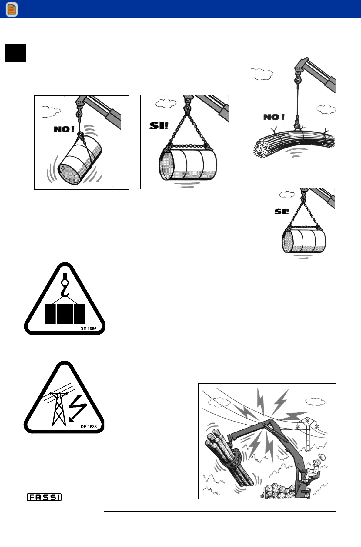
— the minimum safe working distances from power lines are observed.
— the load is correctly slung and hooked.
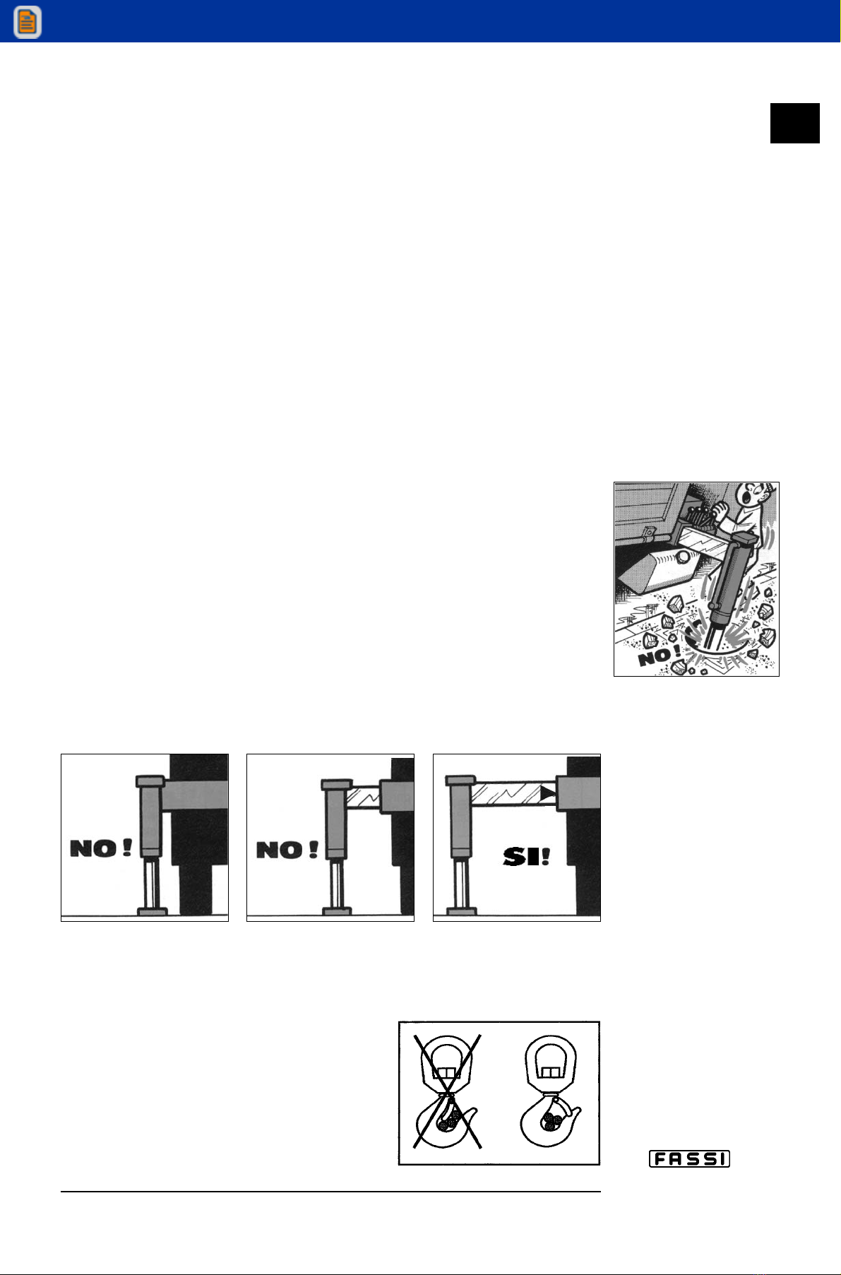
5 — Stabilize the vehicle by the outrigger rams, making sure that:
— the lateral supports are fully extended
— the wheels are in contact with the ground and the suspension is not
completely unloaded
— the outriggers safety taps are closed.
6 — Use the crane in accordance with the use and maintenance manual,
making sure that:
— the load and radii are within the maximum limits shown on
the crane capacity plate
— the crane is used progressively avoiding sudden load movements
— swinging or dragging of the load is avoided
— the load is lifted before rotating.
7 — When using implements protect the crane working area with a barrier.
8 — The vehicle/crane are not left unless the power take off is disenga-
ged and the load is on the ground.
9 — Before driving the vehicle make sure that the outriggers are fully
retracted and re-entered, the safety taps closed and the crane is in
folded position.
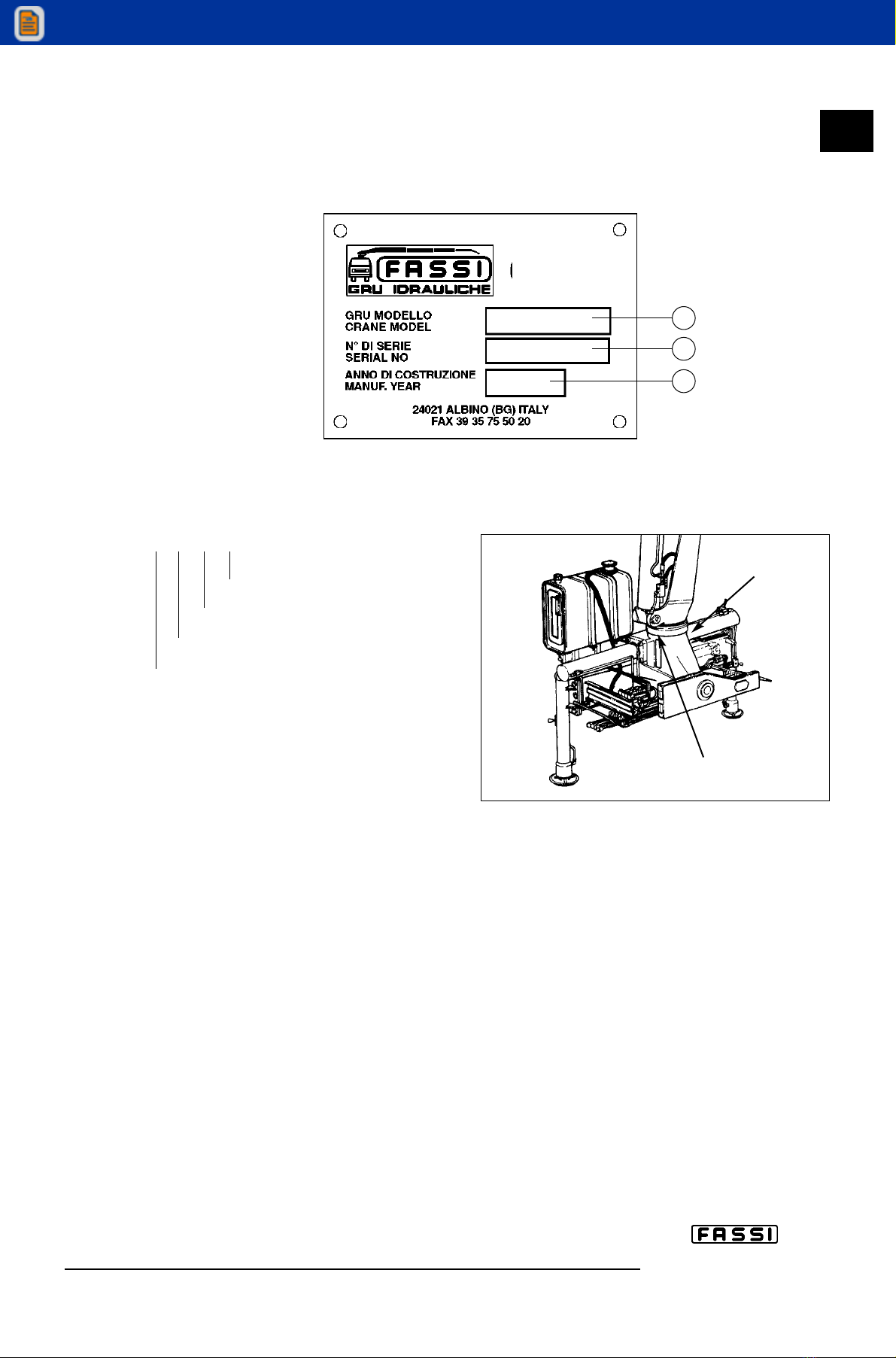
fig. 1
c III
THESE INSTRUCTIONS FOR THE USE OF THE CRANE COINCIDE WITH THOSE
OF THE PLATE DE1771 (FIG. 1) PLACED NEXT TO THE CRANE.