Fast Master Products SWIVELWHEEL-46 User manual


2
SWIVELWHEEL-46
COMPONENTS
Torsion
Suspension and
Tire
Front Jack Stand Legs
with Wheels
3” x 1” Rectangular
Steel Tubing Frame
Optional
Spare Tire
Two Point Hook-Up Hitch
Assembly
¾” Treated/Painted
Plywood Decking
Front Support
Mounts
DOT Lighting Wiring
Harness with 4-Wire
Flat Trailer Plug
DOT Regulated
Lighting
2” x 2” ID
Stake Bed
Receivers

3
CAUTIONS &
DISCLAIMERS
1. SYSTEM MUST BE UNLOADED AT THE TIME OF
CONNECTING TO AND DISCONNECTING FROM
THE TOW VEHICLE.
2. WHEN LOADED, THE DECK SHOULD BE LEVEL
OR SLIGHTLY LOWER IN THE FRONT. NEVER
PULL THE SWIVELWHEEL-46 SYSTEM WITH THE
REAR DECK LOWER THAN THE FRONT, OR
MORE WEIGHT TO THE REAR THAN THE FRONT.
ALWAYS LOAD AND UNLOAD THE
SWIVELWHEEL DECK WHILE ON LEVEL
GROUND.
3. ALWAYS CONNECT AND DISCONNECT THE
SWIVELWHEEL SYSTEM WHILE ON LEVEL
GROUND.
4. BE SURE THAT THE HITCH MOUNTING BOLT
HAS BEEN FULLY TIGHTENED PRIOR TO USE.
CHECK THE MOUNTING BOLT FROM TIME TO
TIME FOR TIGHTNESS
5. IF ATTACHING TO A FIFTH WHEEL TRAILER, DO
NOT EXCEED THE INSTALLED HITCH LOAD
RATING. DO NOT EXCEED THE WEIGHT
CAPACITY OF THE SYSTEM.
6. PAYLOAD MUST BE CONFINED TO WITHIN THE
FRAME PERIMETER OF THE SYSTEM.
7. WHEN BACKING THE SYSTEM UP, BE AWARE OF
CURBS, PARKING STOPS AND POT HOLES.
8. DO NOT BACK UP AT A HIGH RATE OF
SPEED.DAMAGE MAY OCCURE TO THE SYSTEM.
9. WHEN BACKING, SYSTEM DECK HEIGHT MAY
LOWER SLIGHTLY.THIS IS NORMAL.
10. SYSTEM NOT INTENDED FOR PASSENGER USE.
11. MAKE SURE THAT LOADING RAMPS ARE
LOCKED INTO POSITION AND SECURE PRIOR
TO USE.
12. IF USING LOADING RAMPS, REMOVE PRIOR
TO MOVING THE SYSTEM.
13. IF USING THE FAST MASTER LOADING RAMPS
AS SIDE GUARDS, BE SURE THAT THE RAMPS
ARE SECURELY LOCKED INTO PLACE PRIOR
TO MOVING.
14. REPLACEMENT TIRES MUST BE A SIZE 5.70-
8”, “C”RATED, 6-PLY 910 LB, HIGHWAY SPEED
TRAILER TIRE. CHECK TIRE PRESSURE
FREQUENTLY. MOST TIRE FAILURES ARE DUE
TO OVER OR UNDER INFLATION. (75 PSI
COLD). THE TIRE MANUFACTURER SPECIFIES
75 PSI COLD FOR THIS TIRE. NEVER
REDUCE THE TIRE PRESSURE WITHIN A
HOT TIRE. ALWAYS ALLOW THE TIRE TO
COOL FULLY BEFORE REDUCING ANY
TIRE PRESSURE.
15. NEVER REPLACE THE SYSTEM TIRE WITH A
LOWER RATED TIRE.
16. COMPLY WITH ALL STATE AND LOCAL
LICENSING AND REGISTRATION LAWS WHERE
APPLICABLE.
17. WHEN USING THE JACK STANDS, THE SYSTEM
MUST BE UNLOADED. DO NOT LEAVE SYSTEM
DETACHED FROM TOW VEHICLE IN THE
LOADED CONFIGURATION.
18. DO NOT EXCEED 65 MPH. THE
MANUFACTURER OF THE TIRE (CARLISLE)
STATES THAT THE MAXIMUM SPEED FOR A
5.70 X 6 C-RATED, 6-PLY TIRE IS 65 MPH.
HIGHER SPEEDS COULD INCREASE THE HEAT
GENERATED WITHIN THE TIRE AND COULD
CAUSE TIRE FAILURE.
19. CHECK THE BEARING ASSEMBLY TO THE
SWIVEL WHEEL ASSEMBLY ONCE A YEAR.
CHECK AND TIGHTEN THE WHEEL LUG NUTS
ON A ROUTINE BASIS. SERVICE THE WHEEL
BEARINGS ONCE A YEAR OR EVERY 10,000
MILES.
20. MODIFICATIONS TO THE SWIVELWHEEL
SYSTEM WITHOUT WRITTEN APPROVAL
FROM FAST MASTER PRODUCTS WILL
RELEASE FAST MASTER PRODUCTS FROM
ALL LIABILITIES, AND WILL VOID ALL
WARRANTIES.

4
SYSTEM
SPECIFICATIONS
TOW VEHICLE:
CLASS “A” DIESEL MOTOR COACH
CLASS “A” GAS MOTOR COACH
CLASS “C” MOTOR COACH
CLASS-“B” MOTOR HOME
FIFTH WHEEL TRAVEL TRAILER
PICKUPS
SUV’s
AUTOMOBILES
HITCH REQUIREMENTS:
CLASS-III 5000 POUND LOAD @ 500 LB
TONGUE WEIGHT
CLASS-IV 10,000 POUND LOAD @ 1000
LB TONGUE WEIGHT
WEIGHT LIMIT:
600 POUNDS
FRAME:
3” X 1” RECTANGULAR TUBULAR STEEL FRAME.
NOT ANGLE IRON.
DECK DIMENSIONS:
DECK WIDTH = 6’
DECK LENGTH = 4’
DECK HEIGHT:
25¾” TRAILING POSITION (EMPTY/LEVEL DECK)
WITH 8” WHEEL ASSEMBLY.
DECK CONSTRUCTION:
¾” TREATED & PAINTED PLYWOOD
AXLE:
TORSION, 360 DEGREE SWIVEL AXLE
WHEEL/TIRE:
5-SPOKE, WHITE MAG WHEEL (STANDARD)
5.70-8” “C”-RATED, 6-PLY, HIGH SPEED
HIGHWAY TRAILER TIRE @ A COLD INFLATION
PRESSURE OF 75 PSI, AND MAXIMUM 910
POUND LOAD RATING.
LIGHTING:
RUNNING LIGHTS, RT & LT TURN, STOP
LIGHTS, & LICENSE PLATE LIGHTING.
4-WIRE FLAT TRAILER PLUG (STANDARD)
6-WAY ROUND to 4-WIRE FLAT ADAPTER
(OPTIONAL)
7-WAY ROUND to 4-WIRE FLAT ADAPTER
(OPTIONAL)
TIE DOWN POINTS:
OPTIONAL VERTICAL POWDER COATED E-
TRACK ON RIGHT AND LEFT DECK SURFACE
E-TRACK TIE-OFF ADAPTERS. (OPTIONAL)
LOADING RAMPS:
7’-6” LONG x 45” WIDE THREE PIECE. LATCHES
TO THE REAR OF THE SYSTEM.
TOW-VEHICLE MOUNTING:
ONE PERSON, ADJUSTABLE HEIGHT, PIVOTING
MOUNTING HARDWARE.
JACK STANDS:
REMOVABLE, JACK STAND LEGS WITH WHEELS
MAY BE USED TO ROLL SYSTEM AROUND WHILE
DISCONNECTED FROM THE TOW VEHICLE.
SYSTEM WEIGHT LIMITS:
600 POUNDS

5
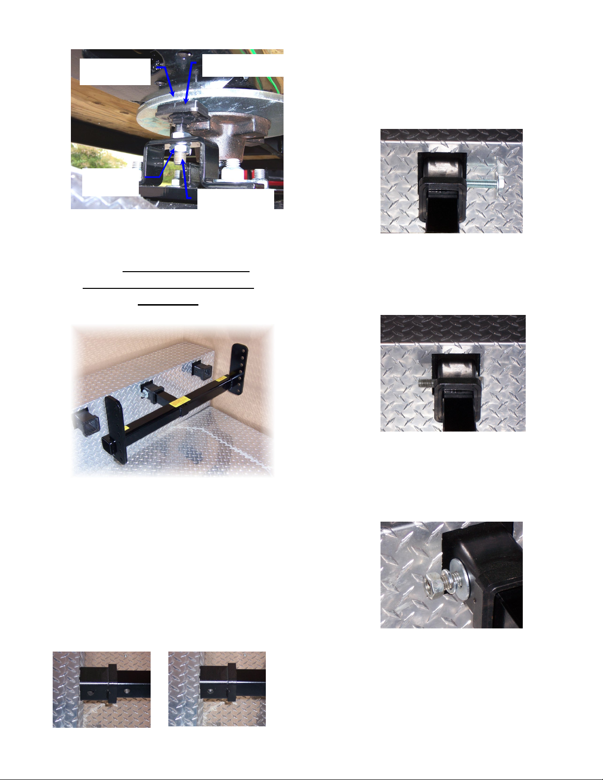
ASSEMBLY
INSTALLING THE TORSION
SUSPENSION
The Swivelwheel-46 system is shipped to you
unassembled to reduce the freight costs. These
instructions will guide you through the assembly
process. Once you receive the system, remove the
components from the boxes.
1. Place the Swivelwheel-46 frame with the
plywood decking facing upward on a pair
of sawhorses.
2. Remove the plywood hatch from the
frame. At the rear of the frame, in the
center, you will find the swivel box for
mounting the torsion suspension.
3. Remove the lug nuts from the studs on
the swivel mount on the torsion
suspension. There should be a round
silver rotor plate slid over the swivel
mount. Do not remove this plate
4. With another persons help, lift the torsion
suspension up into the swivel mount plate
on the Swivelwheel-46 frame. Start a
couple of lug nuts on the studs. You may
now release the torsion suspension and it
will stay in place. Install the remaining lug
nuts and tighten. When attached to the
base frame, the assembly should look like
the next drawing. Torque 90-110 lbs.
5. Remove the lug nuts from the wheel
assembly spindle if not already done so.
Install the wheel and tire to the assembly.
Replace the lug nuts and tighten. Torque
90-110 lbs.
Lug Nuts
Torsion
Suspension Tube
Lug Nuts

6
TAIL LIGHT MOUNTING
1. Install the lights to the rear of the
trailer. The lights should be marked
“Passenger” and “Driver” side. If
not, the light with the clear bottom
lens is always mounted on the
driver side.
2. Connect the light wires to the trailer
wiring harness with the installed
quick disconnects. These wires are
all color coded so match them up
and plug them into each other.
Passenger Side = Brown,
Green, White
Driver Side = Brown,
Yellow, White
3. Install the right and left side jack
stand legs to the front outside 2” x
2” stake bed receivers and lock into
place with the supplied lock pins.
ADJUSTING THE FRICTION
ROTOR ASSEMBLY
ALL SWIVELWHEEL SYSTEMS ARE
SHIPPED WITH A FRICTION ROTOR AND PAD
ASSEMBLY
1. Adjust the friction pad so that it touches the
friction plate (Red Disk) at there is slight
tension between the friction plate and
friction pad.
2. Once the correct amount of friction is
applied, tighten the mounting jam nuts to
hold the friction pad (Blue) in place.
3. You will notice that some pressure at the
rear of the Swivelwheel system is needed in
order to turn the wheel while moving the
system around. This is normal. When the
system is being towed, the wheel assembly
will turn as designed. If you notice that you
cannot move the system around without
really having to push hard, the friction pad
may be too tight.
4. You may hear a slight squeaking noise when
the wheel turns. This is normal due to the
friction pad turning on the rotor plate.
2” x 2” ID
Receiver
Friction
Plate
FRICTION PAD
(Blue)
7
SINGLE RECEIVER
MOUNTING TO THE TOW
VEHICLE
The Single Receiver Hitch will slide into a standard
Class-III or Class-IV receiver on the tow vehicle. If
you do not have this class of receiver, one must be
installed in order to use the system. Check the
vehicles Owners Manual for towing specifications.
Do not exceed the receiver weight rating on
your tow vehicle.
1. Slide the hitch solid 2” x 2” OD insert into
the tow vehicles Class-III or Class-IV
receiver. Line up the mounting hole on the
hitch with the hole on the receiver.
2. Insert the 5/8” x 4” Gr-8 mounting
bolt with 5/8” lock washer from the
passenger side, through the receiver
and into the hitch insert. The insert
is threaded about half way through.
3. Screw the bolt into the insert. Do not
cross thread the bolt. Once the bolt is
inserted all of the way in, tighten the bolt
head fully. This takes out any play within
the hitch assembly.
4. Install the 5/8” lock washer and 5/8” nut
to the bolt. Tighten just enough to
compress the lock washer and then a
slight amount more. Do not over
tighten this nut.
(15/16” Socket or Wrench)
You should now be able to attempt to move the
hitch without any play in the mount. Inspect the
bolt tightness from time to time. If there is play
in the hitch assembly, re-tighten the mounting bolt.
JAM NUT
FRICTION
ROTOR
FRICTION PAD
FRICTION PAD
ADJUSTMENT
BOLT

8
ATTACHING THE
SWIVELWHEEL-46 SYSTEM TO
THE HITCH MOUNT
1. Roll the swivelwheel-46 system up to the
hitch mount on the tow vehicle.
2. Line up the two Adjustable Mounting
Plates (Upper Right Photo) with the center
of the Support Brackets on the front of the
Swivelwheel-46 system.
3. Slide the uprights between the mounting
brackets.
4.Raise one corner of the system to the
closest upward hole position and insert
the supplied 5/8” x 3” bent hitch pin
through the mounting holes.
5. Repeat this procedure for the other side of
the system.
6. Continue raising the deck sides until you
achieve a deck position of slightly lower in
the front than the back. In this position,
when loading the deck, the platform will
lower slightly to a level position for travel.
NOTE:
You may have to adjust the deck a couple of
times to get the correct position. Never have
the rear deck lower than the front while
traveling. If you cannot achieve a level
position, it is better to have a slightly lower
front deck. Once you get the deck
positioned properly for the load, you will
know where to set it each time you haul
that specific item.
7. You may raise the jack stand legs and pin
them in the up position by utilizing the
lower mounting holes.
8. If you wish to remove the jack stand legs
for travel - as you are making the deck
height adjustment, raise the deck slightly
higher at the corner and slide the leg out
of the stake bed receiver.
The photo above left shows the
Jack Stand Legs in the down
position for moving the system
around while disconnected from
the tow vehicle.
The photo above right shows the
Jack Stand Legs raised and pinned
for travel.
Adjustable
Support Plate
Swivelwheel-46
Support Brackets
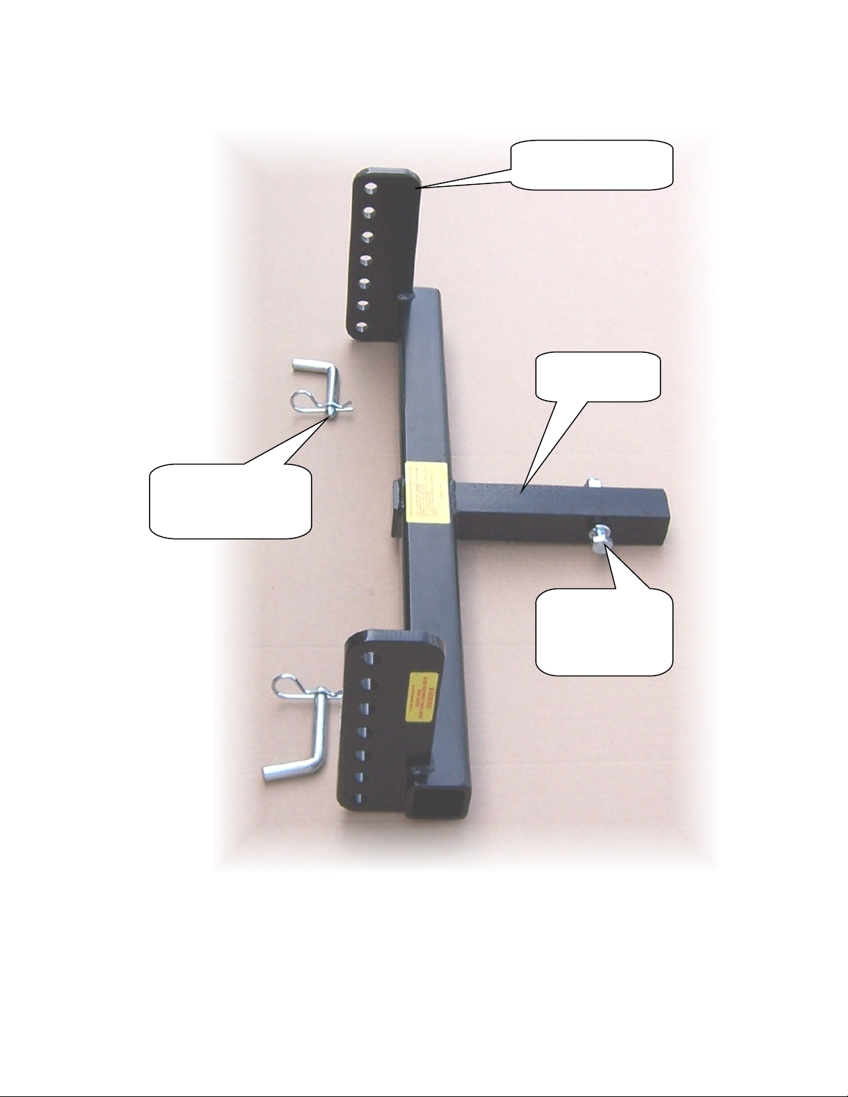
9
Adjustable Support
Plate
5/8” x 4” Grade-8
Hex Bolt with
Lock Washers
and Nut
2” x 2” Solid
Steel Insert
5/8” x 3”
Bent Hitch Pin with
Hair Pin Cotter

10
OPTIONAL LOADING RAMPS
1. Lay the Loading Ramps out to the side or
rear of the Swivelwheel-46 system as shown
below. The two side ramps have red fingers
that extend over the deck edge. The center
ramp has an aluminum plate that extends
over the deck edge.
2. All ramp sets come with safety straps.
Follow the inserted instructions with the
straps to keep the ramps from moving while
in use.
3. The two outside ramps have a load rating of
750 pounds. The center ramp has a load
rating of 1500 pounds. This is sufficient for
any full size motorcycle.
If so desired, you could transport two ATV’s with
the system. By dropping the tailgate, one ATV may
be loaded into the pickup bed. Close the tailgate and
load the second unit onto the Swivelwheel-46.
LOADING THE PLATFORM
1. Always load and unload on level ground. A
good starting point is to level the deck on
the hitch bar, then drop it down one hole so
that the deck is slightly lower in the front
than the rear. As the deck is loaded, the
deck will lower slightly. You want the deck
as level as possible when fully loaded. If you
cannot achieve a level deck, it is better to
have the deck slightly lower in the front
than the rear.
2. Make sure that the systems suspension and
wheel are in the trailing position. This will
reduce the amount of drop in the rear of the
deck while loading. If the tire is turned
around to the front of the system the deck
will lower more due to the leverage applied
to the rear of the system.
3. When using loading ramps, make sure that
the ramps are secure to the Swivelwheel
platform before loading. Do not use
unneeded power when loading to keep the
loading ramps from shooting out from under
the wheels.
4. Ride onto the platform slowly in order to
keep your balance especially with a
motorcycle. Be aware of the opposite end of
the platform. Do not ride off of the opposite
11
end of the platform. If using a wheel chock
for motorcycles, be sure that motorcycles
front tire is lined up with the chock. Ride
into the chock slowly.
MAINTENANCE
BEARINGS: The Swivelwheel-46 systems wheel
hub assembly should be inspected from time to time
to assure there is sufficient grease. These hubs have
quality bearings installed. There should be no reason
for the bearings to fail as long as the grease level is
maintained. The Bearings should be repacked yearly
or every 10,000 miles as most trailer hubs.
The upper swivel hub has a access hatch cut out of
the deck material. This allows for the swivel hub
inspection. This hub turns very little. The only time
the wheel spins 360 degrees is when you back up.
Otherwise the wheel turns about 15 degrees during
travel and at a full turn. The photo right shows a
Dodge 3500 one ton, four door, with 8-foot bed in a
360 degree turn. This shows the maximum wheel
turn on the Swivelwheel during normal travel.
FRAME: From time to time scratches will
develop on the frame. These scratches may be
touched up with a good Rust-Oleum Black Semi-
Gloss spray paint. Most of these are fast drying
paints. If you get the enamel paints, expect to wait
24 hours to fully dry.
DECK: The top deck is painted with Black
Premium Outdoor Gloss paint. The plywood used on
the deck of the Swivelwheel-46 system is pressure
treated. The bottom of the deck is not painted
because it does not need to be. If you want to paint
the bottom of the plywood you may do so.
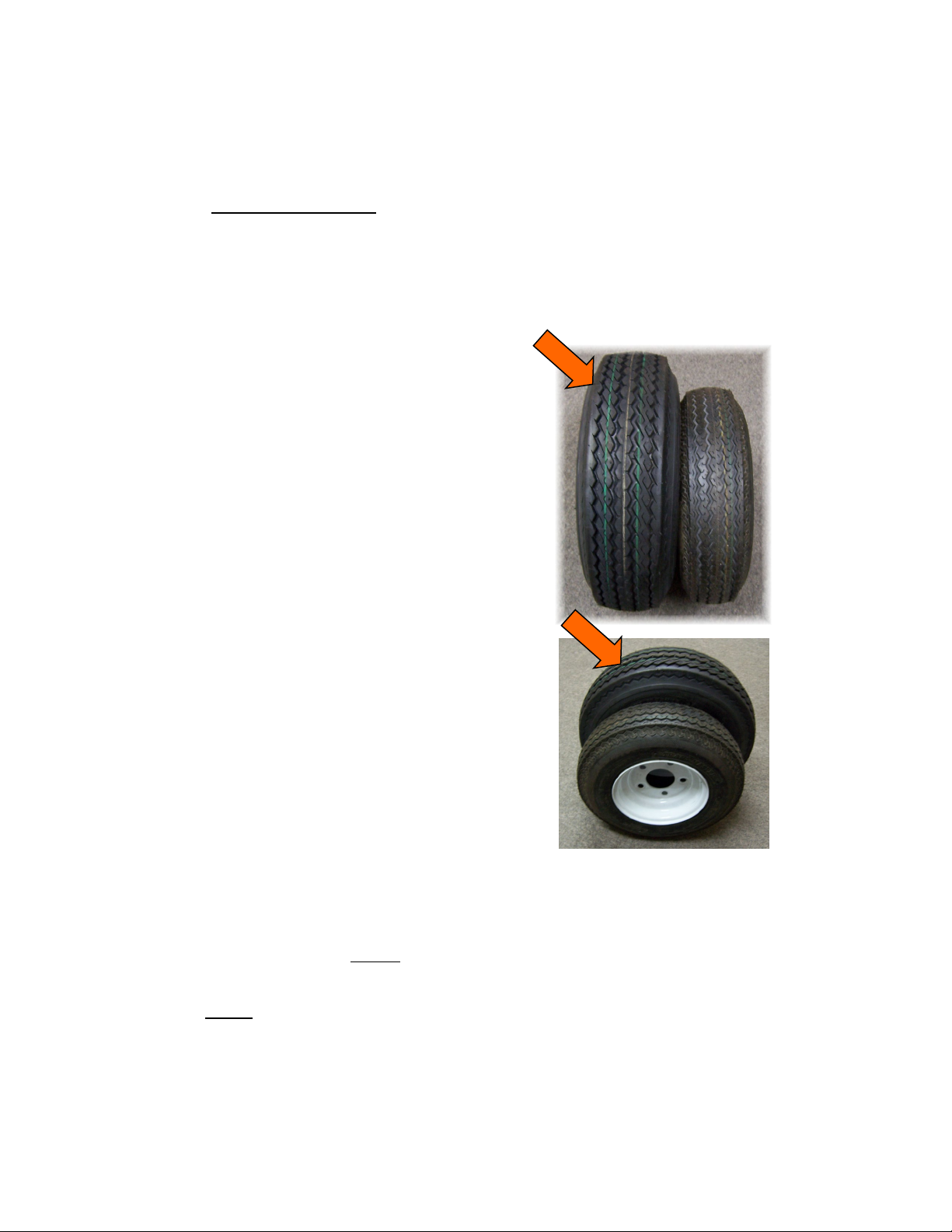
TIRE: The tire is a 5.70 x 8”, C-Rated, 6-
Ply, Highway Speed Trailer Tire. The load rating with
this tire is 910 pounds @ 75 psi cold inflation. This
tire will never see 910 pounds with a 600 pound
deck load. Never replace this tire with a lower
rated tire. This tire was chosen to fit the torsion
suspension being utilized. A larger tire will not fit
this system. Always check tire pressures prior
to using, and always when the tire is cold.
Maintain a 75 psi “cold” inflation pressure in this
tire. The tire left in the photo is the 5.70 x 8” tire
that is used with the Swivelwheel system. The tire to
the right of it is a 4.80 x 8” tire that is usually sold at
Wal-Mart, etc.
This tire is highway speed rated for 65 mph.
I know what you’re thinking! I drive at 70 and 75
mph when I travel. I know that some highways have
speed limits of 75 mph, but the trailer tire
manufacturers have told us that the majority of the
trailer tires on the market today have a speed rating
of 65 mph. Some fifth wheel trailers use a light truck
tire (LT235/75R16) that will withstand higher speeds
and have an 80 psi cold inflation pressure.
The fact is …… tire ratings are specified by the tire
manufacturers. All I can say is that what you choose
to do with that information is up to you.
The tire indicated by the arrow is the tire used with
all Swivelwheel systems.
TORSION SUSPENSION:
There is no maintenance required for this
suspension other than occasionally inspecting the U-
Bolts for tightness.

12
POLICY / RETURNS
IT IS THE POLICY OF FAST MASTER
PRODUCTS TO OFFER THE HIGHEST QUALITY
PRODUCT AT THE BEST POSSIBLE PRICE.
ALL FAST MASTER PRODUCTS ARE FULLY
ASSEMBLED AND TESTED PRIOR TO
SHIPPING. THIS REDUCES THE POSSIBILITY
OF THE UNFORTUNATE SURPRISE FACTOR OF
NOT RECEIVING A PART, OR OF HAVING A
MALFUNCTION OUT OF THE BOX.
UNFORTUNATELY, MURPHY COULD STILL
RAISE HIS UGLY HEAD.
WE ARE PROUD OF OUR QUALITY
CONTROLS AND CUSTOMER SERVICE. IF AN
ISSUE DOES ARISE WITH ONE OF OUR
PRODUCTS, SUCH AS FREIGHT DAMAGE,
MISSING PARTS, ETC, PLEASE CONTACT US
AS SOON AS POSSIBLE TOLL FREE AT (866)
794-8357.
FREIGHT DAMAGES MUST BE REPORTED
WITHIN 24-48 HOURS IN ORDER FOR US TO
FILE FREIGHT CLAIMS WITH THE CARRIER.
(SEE RETURNS BELOW)
ALL OF THE PRODUCTS MANUFACTURED BY
FAST MASTER PRODUCTS, INC. HAVE BEEN
TESTED UNDER ADVERSE CONDITIONS. USE
OF THESE PRODUCTS BEYOND THE RELM OF
THEIR TESTING MAY CAUSE DAMAGE TO THE
SYSTEM, OR PERSONAL INJURY. PLEASE
READ AND FOLLOW THE GUIDELINES WITHIN
THE CAUTIONS AND DISCLAIMERS SECTION
WITHIN THE SUPPLIED OWNERS MANUAL.
•Modifications or changes made in any
product manufactured by Fast Master
Products, Inc, without written consent
from Fast Master Products, Inc. will void the
warranty and product liability insurance
associated with that product.
•The Swivelwheel system was not designed
or tested for towing from another towed
vehicle behind a motor coach (Triple Towing
behind a motor coach).
The weight and mass of the Swivelwheel trailer
in conjunction with a towed vehicle behind a
motor coach may cause the combination to
become unstable and uncontrollable. Fast
Master Products, Inc. will not be held
responsible for damage or injury from such
a combination use.
•The swivel wheel and suspension
components are not a sellable component
off of the system. These components are a
proprietary component of the Swivelwheel
product. Replacement suspension parts are
available to customers with Swivelwheel
products only. When ordering, please
provide the name of the owner and the VIN
number associated with the system.
DEALERS:
All dealer sells are final and nonrefundable.
•If a customer has any questions or concerns
about installation please call Fast Master
Products, Inc. at 1-866-794-8357
RETURNS:
Fast Master Products, Inc. sells all Swivelwheel
products as a titled product. Since it is a titled
product there is no return or refund once the title
has been issued to the customer. With that being
said:
•Please Note: If there is any freight damage
noted upon delivery, note the damage on
the freight bill and contact Fast Master
Products, Inc. right away with the
information. Fax a copy of the freight bill to
us at (281) 391-6760. This must be done
within 24-48 hours to allow us to file a
freight claim with the carrier. If available,
take pictures and email them to
info@cruiserlift.com. If this procedure is not
followed, we must assume that the damage
occurred after the delivery date.

13
WARRANTY POLICY: All systems
(Swivelwheel, Cruiserlift, CruiserRamp) have
a one year warranty from the date of the
original invoice. NOTE: Removing the VIN
sticker from our systems will void all warranty
and return possibilities. In addition, Warranty
is not transferable from the original owner of
the system.
•Modifications or changes made in any
product manufactured by Fast Master
Products, Inc, without written consent
from Fast Master Products, Inc. will
void the warranty and product liability
insurance associated with that
product.
WARRANTY REPLACEMENT
PARTS:
In the event of warranty replacement parts, we will
bill you for the part being sent to you unless
otherwise directed by Fast Master Products, Inc.
management. Once the defective part has been
returned to Fast Master Products, Inc, and found
that it was a warranty issue, you will be credited for
the charge.
The defective component must be returned
within 15 days, or credit cannot be issued. This
policy has had to be implemented due to the
following reason.
•As other manufacturers, some of our
components are purchased from outside
vendors. These vendors also have a
warranty return policy. When we send a part
out under warranty, and do not receive the
defective component, we cannot file a
warranty claim with that specific vendor for
repair or replacement under their policy
deadlines.
MODEL No: SWIVELWHEEL-46
VIN No:
Table of contents
Other Fast Master Products Automobile Accessories manuals


Popular Automobile Accessories manuals by other brands


ULTIMATE SPEED
ULTIMATE SPEED 279746 Assembly and Safety Advice

SSV Works
SSV Works DF-F65 manual

ULTIMATE SPEED
ULTIMATE SPEED CARBON Assembly and Safety Advice

Witter
Witter F174 Fitting instructions

WeatherTech
WeatherTech No-Drill installation instructions

TAUBENREUTHER
TAUBENREUTHER 1-336050 Installation instruction