Fast Master Products SWIVELWHEEL-58 User manual

1
SWIVELWHEEL-58
OWNERS MANUAL /ASSEMBLY INSTRUCTIONS.
Fast Master Products, Inc.
P.O. Box 654, Katy Texas 77492-0654
Tel: (281) 391-6750 Fax: (281) 391-6760
Email: i[email protected]

2
SWIVELWHEEL-58 COMPONENTS
Front Jack Stand Legs with
Wheels
Standard Two Point
Hitch Assembly
Optional Spare Tire
& Wheel
5.70 x 8 8-Ply, D-Rated,
Highway Speed Trailer
Tire & Torsion
Suspension
2” x 2” ID
Stake Bed
Receivers
¾” Treated/Painted
Plywood deck
Swivel Access
Hatch Cover
3” x 1 ½” Rectangular
Tubing Steel Frame

3
CAUTIONS & DISCLAIMERS
1. SYSTEM MUST BE UNLOADED AT THE TIME OF
CONNECTING TO AND DISCONNECTING FROM THE
TOW VEHICLE.
2. THE SWIVELWHEEL-58 SYSTEM IS NOT
INTENDED FOR SHORT-NARROW WHEEL BASE
VEHICLES. USE ONLY WITH FULL SIZE PICK-UPS,
MID TO FULL SIZE SUV’S (EXPIDITION, TAHOE,
ETC), CLASS-A AND CLASS-C MOTOR COACHES, AND
FIFTH WHEEL TRAVEL TRAILERS.
3. WHEN LOADED, THE DECK SHOULD BE LEVEL OR
SLIGHTLY LOWER IN THE FRONT. NEVER PULL THE
SWIVELWHEEL-58 SYSTEM WITH THE REAR DECK
LOWER THAN THE FRONT, OR MORE WEIGHT TO
THE REAR THAN THE FRONT. NEVER LOAD OR
UNLOAD THE SWIVELWHEEL PLATFORM ON AN
INCLINE. ONLY LOAD OR UNLOAD ON LEVEL
GROUND.
4. NEVER DISCONNECT THE SWIVELWHEEL
SYSTEM WHILE PARKED ON AN INCLINE.
ALWAYS CONNECT AND DISCONNECT THE
SYSTEM ON LEVEL GROUND.
5. BEFORE DISCONNECTING THE SWIVELWHEEL FROM
THE VEHICLE MAKE SURE SUSPENSIONS ARE IN THE
DRIVE POSITION. TO PREVENT THE DECK FROM
FLIPPING.
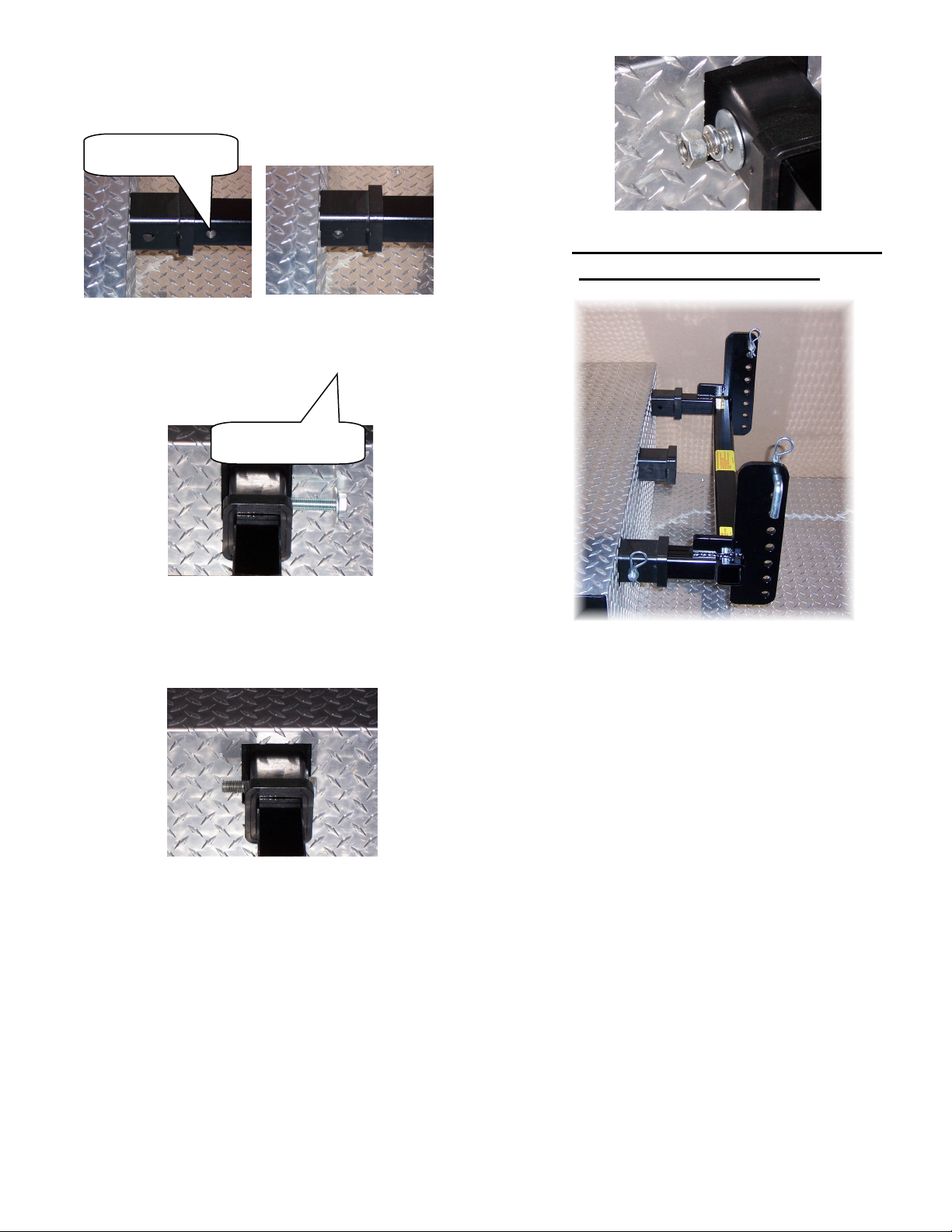
6. BE SURE THAT THE HITCH MOUNTING BOLT HAS
BEEN FULLY TIGHTENED PRIOR TO USE. CHECK THE
MOUNTING BOLT FROM TIME TO TIME FOR
TIGHTNESS
7. IF ATTACHING TO A FIFTH WHEEL TRAILER, DO
NOT EXCEED THE INSTALLED HITCH LOAD RATING.
DO NOT EXCEED THE WEIGHT CAPACITY OF THE
SYSTEM
8. PAYLOAD MUST BE CONFINED TO WITHIN THE
FRAME PERIMETER OF THE SYSTEM.
9. WHEN BACKING THE SYSTEM UP, BE AWARE OF
CURBS, PARKING STOPS AND POT HOLES.
10. DO NOT BACK UP AT A HIGH RATE OF
SPEED.DAMAGE MAY OCCURE TO THE SYSTEM.
11. WHEN BACKING, SYSTEM DECK HEIGHT MAY LOWER
SLIGHTLY.THIS IS NORMAL.
12. SYSTEM NOT INTENDED FOR PASSENGER USE.
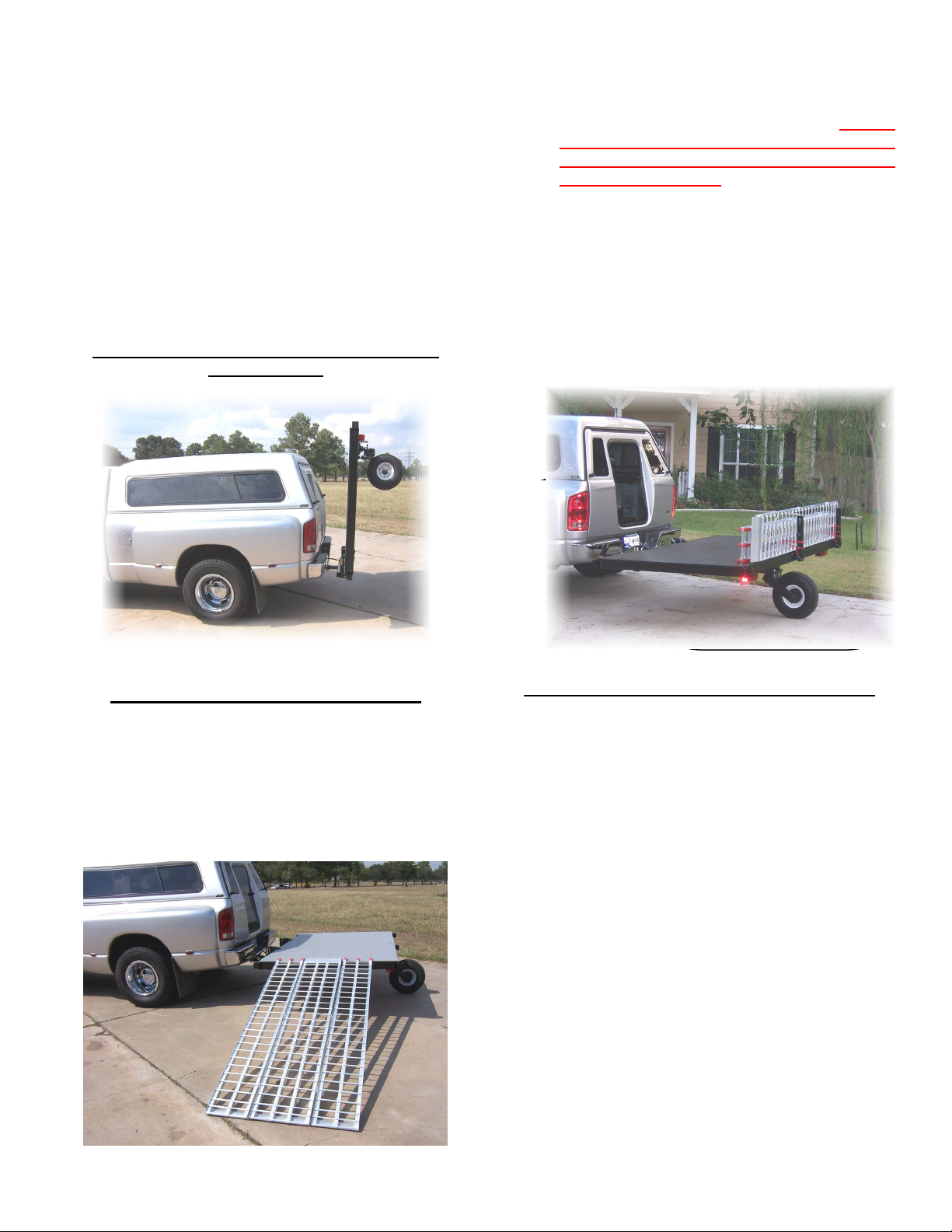
13. MAKE SURE THAT LOADING RAMPS ARE LOCKED
INTO POSITION AND SECURE PRIOR TO USE.
14. IF USING LOADING RAMPS, REMOVE PRIOR TO
MOVING THE SYSTEM.
15. IF USING THE FAST MASTER LOADING RAMPS AS
SIDE GUARDS, BE SURE THAT THE RAMPS ARE
SECURELY LOCKED INTO PLACE PRIOR TO
MOVING.
16. REPLACEMENT TIRES MUST BE A SIZE 5.70-8, “D”
RATED, 1075 LB, HIGHWAY SPEED TRAILER TIRE.
CHECK TIRE PRESSURE FREQUENTLY. MOST TIRE
FAILURES ARE DUE TO OVER OR UNDER
INFLATION. (100 PSI COLD). CARLISLE SPECIFIES
100 PSI COLD FOR THIS TIRE. NEVER REDUCE
THE TIRE PRESSURE WITHIN A HOT TIRE.
ALWAYS ALLOW THE TIRE TO COOL FULLY
BEFORE REDUCING ANY TIRE PRESSURE.
17. NEVER REPLACE THE SYSTEM TIRE WITH A
LOWER RATED TIRE.
18. COMPLY WITH ALL STATE AND LOCAL LICENSING
AND REGISTRATION LAWS WHERE APPLICABLE.
19. IF DIAMOND PLATE ORDERED WITH SYSTEM, BE
AWARE THAT THE DIAMOND PLATE MAY BE
SLIPPERY WHEN WET.
20. WHEN USING THE JACK STANDS, THE SYSTEM
MUST BE UNLOADED. DO NOT LEAVE SYSTEM
DETACHED FROM TOW VEHICLE IN THE LOADED
CONFIGURATION.
21. DO NOT EXCEED 65 MPH. THE MANUFACTURER
OF THE TIRE (CARLISLE) STATES THAT THE
MAXIMUM SPEED FOR A 5.70 X 8”, D-RATED, 8-
PLY TIRE IS 65 MPH. HIGHER SPEEDS COULD
INCREASE THE HEAT GENERATED WITHIN THE
TIRE AND COULD CAUSE TIRE FAILURE.
22. CHECK THE BEARING ASSEMBLY TO THE SWIVEL
WHEEL ASSEMBLY ONCE A YEAR. CHECK AND
TIGHTEN THE WHEEL LUG NUTS ON A ROUTINE
BASIS. SERVICE THE WHEEL BEARINGS ONCE A
YEAR OR EVERY 10,000 MILES.DO NOT DRIVE
WITH THE SYSTEM IN THE FLIPPED UP POSITION.
23. MODIFICATIONS TO THE SWIVELWHEEL SYSTEM
WITHOUT WRITTEN APPROVAL FROM FAST
MASTER PRODUCTS WILL RELEASE FAST MASTER
PRODUCTS FROM ALL LIABILITIES, AND WILL
VOID ALL WARRANTIES.
24. THE SWIVELWHEEL-58 SYSTEM WAS NOT
DESIGNED FOR TOWING BEHIND “LITE”
CONFIGURATION TRAILERS SUCH AS BELOW 30
FEET IN LENGTH AND UNDER 10,000 POUNDS
GVWR.

4
SYSTEM SPECIFICATIONS
TOW VEHICLE:
CLASS “A” DIESEL MOTOR COACH
CLASS “A” GAS MOTOR COACH
CLASS “C” MOTOR COACH
FIFTH WHEEL TRAVEL TRAILER
FULL SIZE PICK-UP
MID TO FULL SIZE SUV’S (EXPIDITION, TAHOE,
SUBURBAN, ETC)
HITCH REQUIREMENTS:
CLASS-III 5000 POUND LOAD @ 500 LB
TONGUE WEIGHT
CLASS-IV 10,000 POUND LOAD @ 1000
LB TONGUE WEIGHT
SYSTEM LOAD / WEIGHT LIMITS:
CLASS-III RECEIVERS = 850 POUNDS
CLASS-IV RECEIVERS = 1000 POUNDS
FRAME:
RECTANGULAR TUBULAR STEEL FRAME
DECK DIMENSIONS:
DECK WIDTH = 8’
DECK LENGTH = 5’
DECK HEIGHT:
25¾” TRAILING POSITION (EMPTY / LEVEL
DECK).
DECK CONSTRUCTION:
¾” TREATED & PAINTED PLYWOOD
AXLE:
TORSION, SWIVEL AXLE
WHEEL / TIRE:
5-SPOKE, WHITE MAG WHEEL (STANDARD)
5.70-8 “D” RATED, 8-PLY, HIGH SPEED
HIGHWAY TRAILER TIRE @ 1075 POUNDS
RATING.
LIGHTING:
RUNNING LIGHTS, RT & LT TURN, STOP
LIGHTS, & LICENSE PLATE LIGHTING.
4-WIRE FLAT TRAILER PLUG (STANDARD)
6-WAY ROUND to 4-WIRE FLAT ADAPTER
(OPTIONAL)
7-WAY ROUND to 4-WIRE FLAT ADAPTER
(OPTIONAL)
TIE DOWN POINTS:
VERTICAL POWDER COATED E-TRACK ON
RIGHT AND LEFT DECK SURFACE
A-TRACK TIE-OFF ADAPTERS. (OPTIONAL)
TOW-VEHICLE MOUNTING:
ONE PERSON, ADJUSTABLE HEIGHT, PIVOTING
MOUNTING HARDWARE.
JACK STANDS:
REMOVABLE, JACK STAND PEDESTALS WITH
WHEELS
MAY BE USED TO ROLL SYSTEM TO STORAGE
LOCATION.
MISC. OPTIONAL ACCESSORIES:
MOTORCYCLE FRONT WHEEL LOCKING WHEEL
CHOCK (OPTIONAL)
3 PC LOADING RAMP SET
POWER RAMP
CRUISER RAMP MOTORCYCLE LOADER
SPARE TIRE
WEIGHT LIMITS:
1000 POUNDS

5
ASSEMBLY
The Swivelwheel system is shipped to you
unassembled in order to save on freight costs. The
following components will be in the box banded to the
top of the deck.
•2ea Safety Chains w/ mounting bolts.
•2ea Lights (Passenger & Driver Side)
Driver side light has the clear bottom
lens.
•2ea Jack Stand Legs w/ Wheels & Lock Pins.
•1ea Torsion Suspension.
•1ea 5.80 x 8” Wheel & Tire.
•1ea Spare tire if ordered.
•1ea Hitch Assembly.
•2ea 5/8” x 3” Bent Hitch Pins.
ASSEMBLY
INSTALLING THE TORSION
SUSPENSION
The Swivelwheel-58 system is shipped to you
unassembled to reduce the freight costs. These
instructions will guide you through the assembly
process. Once you receive the system, remove the
components from the boxes.
a. Place the Swivelwheel-58 frame with the
plywood decking facing upward on a pair of
sawhorses.
b. Remove the plywood hatch from the center
rear frame. At the rear of the frame, in the
center, you will find the swivel box for
mounting the torsion suspension.
c. Remove the lug nuts from the studs on the
swivel mount on the torsion suspension. There
should be a round silver rotor plate slid over
the swivel mount. Do not remove this
plate.
d. With another persons help, lift the torsion
suspension up into the swivel mount plate on
the Swivelwheel-58 frame. Start a couple of lug
nuts on the studs. You may now release the
torsion suspension and it will stay in place.
Install the remaining lug nuts and tighten. When
attached to the base frame, the assembly should
look like the next photo. If using a torque
wrench = 90-110 lbs.
The below photo does not show the Rotor Plate
and Break Assembly.
e. Remove the lug nuts from the wheel assembly
spindle if not already done so. Install the wheel
and tire to the assembly. Replace the lug nuts
and tighten. Torque 90-110 lbs.
Lug Nuts
Torsion
Suspension Tube
Lug Nuts

6
TAIL LIGHT MOUNTING
1. Installing the lights to the rear of the trailer.
The lights should be marked “Passenger” and
“Driver” side. If not, the light with the clear
bottom lens is always the driver side. This is
for the license plate light. Insert the supplied
bolts with flat washer from the rear frame
inward. Slide the light over the bolt heads.
There are slots on the back of the light
housing. Make sure that the light is square
with the frame. Tighten the nuts to secure
into place.
2. Connect the light wires to the trailer wiring
harness with the installed quick disconnects.
These wires are all color coded so match them
up and plug them into each other.
Right Side = Brown, Green, White
Left Side = Brown, Yellow, White
Driver Side: Optronics ST-17RB
Passenger Side: Optronics ST16RB
WHEEL CHOCK MOUNTING
If you ordered either the V-Style or Locking Wheel
Chock, the mounting holes will already be in the deck.
The holes will be on the driver side middle deck unless
otherwise specified.
1. Set the wheel chock onto the deck over the
mounting holes as shown below.
2. Insert the supplied mounting 5/16” X 4 ½”
hex head bolts and flat washers from the top
downward through the deck and frame.
3. Install the flat washers, lock washers and nuts
to the bolt ends and tighten.
SAFETY CHAIN MOUNTING
Under and behind the front support mounts is a
front to rear cross member. There are holes in both
cross members below the decking. See Red Arrow
below. Attach one Safety Chain to each of the two cross
members. Always be sure to connect the safety chains
to the tow vehicle.
SINGLE RECEIVER MOUNTING
TO THE TOW VEHICLE
The Single Receiver Hitch Assembly will slide into
the standard Class-III or Class-IV receiver on the tow
vehicle. If you do not have this class of receiver, one
must be installed in order to use the system. Check the
vehicles Owners Manual for towing specifications.
Do not exceed the receiver weight rating on
your tow vehicle.
Deck Top
Locking
Wheel Chock

7
1. Line up the mounting hole on the Two Point
Hook-Up Hitch Insert with the hole on the
receiver.
2. Insert the 5/8” x 4” Gr-8 mounting bolt with
5/8” lock washer from the passenger side,
through the receiver and into the hitch insert.
The insert is threaded about half way through.
3. Screw the bolt into the insert. Do not cross
thread the bolt. Once the bolt is inserted all of
the way in, tighten the bolt head fully. This
takes out any play within the hitch assembly.
4. Install the 5/8” lock washer and 5/8” nut to the
bolt. Tighten just enough to compress the lock
washer and then a slight amount more. Do not
over tighten this nut. Check the bolt for
tightness from time to time. If play
develops in the hitch, re-tighten the bolt.
DUAL RECEIVER MOUNTING
TO THE TOW VEHICLE
There is an optional Dual Mount Hitch available for
the Swivelwheel-58 system. This mount includes two
additional 2” x 2” ID x 9” long receivers to be
installed onto the tow vehicle. If attaching to a
motor home, the Cruiserlift three receiver package may
be utilized. Both mounts require welding.
1. Install the additional receivers to the tow
vehicle. The two receivers must be 30” apart,
Center-to-Center.
2. The face of the two connection points must be
either flush to the back of the vehicle or stick
out no more than 4’’ from the back of the
vehicle.
3. Slide the two inserts from the dual hitch
assembly (Right) into the receivers installed
onto the tow vehicle.
4. Line up the holes between the hitch and
receivers. Install the two 5/8” x 3” bent hitch
pins through the mounting holes and add the
hairpin cotters to the ends of the hitch pins to
lock them.
Receiver Hole
Insert Hole

8
ATTACHING THE SWIVELWHEEL-58
SYSTEM TO THE HITCH MOUNT
1. Roll the swivelwheel-58 system up to the hitch
mount on the tow vehicle. This should be done
on level ground.
2. Line up the two Adjustable Support Brackets
with the center of the Front Support Brackets on
the front of the Swivelwheel-58 system.
3. S
l
i
d
e
t
h
e
F
r
o
nt Support Brackets over the adjustable
uprights.
4. Raise one corner of the system to the closest
upward hole position and insert the supplied
5/8” x 3” bent hitch pin through the mounting
holes.
NOTE: The front support bracket has two forward
holes in the plate. One hole three inches below
the other. Depending on the receiver height of
the tow vehicle, utilize the appropriate mounting
hole position to level the deck.
The top rear hole is for the flip-up feature,
explained later in these instructions.
DO NOT
UNDER ANY CIRCUMSTANCES, INSTALL THE
BENT HITCH PINS THROUGH BOTH THE TOP AND
BOTTOM HOLES WHILE TRANSPORTING THE SYSTEM.
THIS WILL NOT ALLOW THE SYSTEM TO PIVOT AT THE
FRONT, AND MAY CAUSE DAMAGE TO THE
SWIVELWHEEL SYSTEM AND/OR THE TOW VEHICLE.
Repeat this procedure for the other side of the system.
Front Support Bracket
USE EITHER THE TOP OR
BOTTOM MOUNTING
HOLE. NOT BOTH AT THE
SAME TIME.
Adjustable
Mounting
Plates
Front Support
Bracket
Swivelwheel
Deck
Adjustable
Mounting
Plates
5/8” x 3”
Bent Hitch
Pin w/Hair
Pin Cotter

9
5. Continue raising the deck sides until you achieve
a deck position of slightly lower in the front than
the back. In this position, when loading the
deck, the platform will lower slightly to a level
position for travel.
NOTE:
You may have to adjust the deck a couple of
times to get the correct position. Never have the
rear deck lower than the front while traveling. If
you cannot achieve a level position, it is better
to have a slightly lower front deck. Once you get
the deck positioned properly for the load, you
will know where to set it each time you haul that
specific item.
6. You may raise the jack stand legs and pin them
in the up position by utilizing the lower
mounting holes.
7. If you wish to remove the jack stand legs for
travel - as you are making the deck height
adjustment, raise the deck slightly higher at the
corner and slide the leg out of the stake bed
receiver.
ADJUSTING THE FRICTION
ROTOR ASSEMBLY
ALL SWIVELWHEEL SYSTEMS ARE
SHIPPED WITH A FRICTION ROTOR AND PAD
ASSEMBLY
1. Adjust the friction pad (Blue Pad)so that it
touches the friction plate (Red Disk). Adjust so
that there is slight tension between the friction
plate and friction pad.
2. Once the correct amount of friction is applied,
tighten the mounting jam nuts to hold the
friction pad in place.
3. You will notice that some pressure at the rear of
the Swivelwheel system is needed in order to
turn the wheel while moving the system around.
This is normal. When the system is being towed,
the wheel assembly will turn as designed. If you
notice that you cannot move the system around
without really having to push hard, the friction
pad may be too tight.
4. You may hear a slight squeaking noise when the
wheel turns. This is normal due to the friction
pad turning on the rotor plate.
FLIPPING THE SYSTEM
UPWARD & LOCKING
System Deck
Top
FLIP-UP
FEATURE
MOUNTING
HOLE ONLY
Friction Pad
3rd Mounting
Hole
Adjustable
Mounting
Plate
Rotor Plate
Torsion
Suspension
Front Support
Bracket

10
1. Lower the Support Brackets upper mounting
hole into the third (3rd) hole from the top of the
Adjustable Mounting Plates. Reinstall the hitch
pins into the third (3rd) hole. Flip up feature
requires two additional 5/8” x 3” hitch pins.
2. With another persons help, lift the rear of the
Swivelwheel-58 system to the upright position.
3. While one person steadies the system, insert the
a 5/8” x 3” Bent Hitch Pin to each side of the
adjustable mounting plate as shown in the
above photo.
The system should look like the photo below
when finished.
OPTIONAL LOADING RAMPS
1. Lay the loading ramps out to the side or rear of
the Swivelwheel-58 system as shown below. The
two side ramps have red fingers that extend
over the deck edge. The center ramp has an
aluminum plate that extends over the deck
edge. These ramps interlock with each other.
2. All ramp sets come with safety straps. Follow
the inserted instructions with the straps to keep
the ramps from moving while in use. Always
use the safety straps to keep the ramps
from spinning out from under the bike
wheel when loading.
3. The two outside ramps have a load rating of 750
pounds. The center ramp has a load rating of
1500 pounds. This is sufficient for any full size
motorcycle.
4. For transport, the ramps may be ratcheted to
the top of the deck or attached as shown below
if desired.
OPTIONAL E-TRACK MOUNTING
If you added the E-track option, you will have two 5-foot
E-Track strips attached to the frame deck. These are
usually attached to the right and left front sides of the
system unless otherwise requested. When using the E-
track mounts, the E-track adapters must be utilized. The
tracks have multiple mounting slots the length of the
track. These tracks have been screwed into the frame of
the Swivelwheel system for strength.
Deck
Painted grey for
instruction purposes
Mounting Pin
5/8” x 3” Bent Hitch
Pin
Mounting Pin
5/8” x 3” Bent Hitch
Pin
Support Mounts

11
These adapters may be purchased a number of fastener
companies. They all have a way to attach ratchet tie-
downs.
LOADING THE PLATFORM
1. Always load and unload on level ground. A good
starting point is to level the deck on the hitch
bar, then drop it down one hole so that the deck
is slightly lower in the front than the rear. As the
deck is loaded, the deck will lower slightly. You
want the deck as level as possible when fully
loaded. If you cannot achieve a level deck, it is
better to have the deck slightly lower in the
front than the rear.
2. Make sure that the systems suspension and
wheel are in the trailing position. This will
reduce the amount of drop in the rear of the
deck while loading. If the tire is turned around
to the front of the system the deck will lower
more due to the leverage applied to the rear of
the system.
3. When using loading ramps, make sure that the
ramps are secure to the Swivelwheel platform
before loading. Do not use unneeded power
when loading to keep the loading ramps from
shooting out from under the wheels.
4. Ride onto the platform slowly in order to keep
your balance especially with a motorcycle. Be
aware of the opposite end of the platform. Do
not ride off of the opposite end of the platform.
If using a wheel chock for motorcycles, be sure
that motorcycles front tire is lined up with the
chock. Ride into the chock slowly.
TYING DOWN CARGO ONTO THE
DECK
When tying any cargo onto the deck, always make sure
that during transportation, the tie-down straps cannot
loosen so that you loose your cargo. When tying down a
motorcycle, the bikes suspension aids in the ride of the
bike. You never compress the shocks fully. This could
damage the shocks. When tying the motorcycle (or
any other cargo that can flex) down with the use
of tie-downs, always insert the S-Hooks in a
fashion where it is in the hardest position to
remove if the tie-down were to loosen. Check all
tie-downs frequently.
If using the stake bed receivers on the Swivelwheel-58
system:
Do not hook the S-hook through the bottom of
the holder. If the bike starts to move from side
to side due to road conditions, the strap on one
side tightens while the other loosens. The loose
side could possibly drop from the bottom of the
receiver. This could start a chain reaction and
you could loose the motorcycle. It may be better
to insert the hook through the receiver, and
hook it over the top of the receiver edge.
MAINTENANCE
BEARINGS: The Swivelwheel-58 system’s wheel hub
assembly should be inspected from time to time to
assure there is sufficient grease. These hubs have
quality bearings installed. There should be no reason for
the bearings to fail as long as the grease level is
maintained. The Bearings should be repacked yearly or
every 10,000 miles as most trailer hubs.
The upper swivel hub has an access hatch cut out of the
deck material. By removing the two screws, the hatch
may be removed. This allows for the swivel hub
inspection. This hub turns very little. The only time the
wheel spins 360 degrees is when you back up.
Otherwise the wheel turns about 10-15 degrees during
travel and at a full turn.
TIRE: The tire is a 5.70 x 8”, D-Rated, 8-Ply,
Highway Speed Trailer Tire. The load rating with this tire
is 1075 pounds @ 100 psi cold inflation. This tire will
never see 1075 pounds with a 600 pound deck load.
Never replace this tire with a lower rated tire. This
tire was chosen to fit the torsion suspension being
utilized. A larger tire will not fit this system. Always
check tire pressures prior to using, and always
when the tire is cold. Maintain a 100 psi “cold”
inflation pressure in this tire.
The photos below show the tire used with the
Swivelwheel system. The taller and wider tires in the
E-Track

12
photos are the 5.70 x 8” tire used with the Swivelwheel
system.
This tire is highway speed rated for 65 mph. I
know what you’re thinking! I drive at 70 and 75 mph
when I travel. I know that some highways have speed
limits of 75 mph, but the trailer tire manufacturers have
told us that the majority of the trailer tires on the
market today have a speed rating of 65 mph. Some fifth
wheel trailers use a light truck tire (LT235/75R16) that
will withstand higher speeds and have an 80 psi cold
inflation pressure.
The fact is …… tire ratings are specified by the tire
manufacturers. All I can say is that what you choose to
do with that information is up to you.
FRAME: From time to time scratches will develop
on the frame. These scratches may be touched up with
a good Rust-Oleum Black Semi-Gloss spray paint. Most
of these are fast drying paints. If you get the enamel
paints, expect to wait 24 hours to fully dry.
DECK: The top deck is painted with Black
Premium Outdoor Gloss paint. The plywood used on the
deck of the Swivelwheel-46 system is pressure treated.
The bottom of the deck is not painted because it does
not need to be. If you want to paint the bottom of the
plywood you may do so.
TORSION SUSPENSION: There is no
maintenance required for this suspension assembly
other than occasionally inspecting the U-Bolts for
tightness.
POLICY /RETURNS
IT IS THE POLICY OF FAST MASTER PRODUCTS
TO OFFER THE HIGHEST QUALITY PRODUCT AT
THE BEST POSSIBLE PRICE.
ALL FAST MASTER PRODUCTS ARE FULLY
ASSEMBLED AND TESTED PRIOR TO SHIPPING.
THIS REDUCES THE POSSIBILITY OF THE
UNFORTUNATE SURPRISE FACTOR OF NOT
RECEIVING A PART, OR OF HAVING A
MALFUNCTION OUT OF THE BOX.
UNFORTUNATELY, MURPHY COULD STILL RAISE
HIS UGLY HEAD.
WE ARE PROUD OF OUR QUALITY CONTROLS
AND CUSTOMER SERVICE. IF AN ISSUE DOES
ARISE WITH ONE OF OUR PRODUCTS, SUCH AS
FREIGHT DAMAGE, MISSING PARTS, ETC, PLEASE
CONTACT US AS SOON AS POSSIBLE TOLL FREE
AT (866) 794-8357.
FREIGHT DAMAGES MUST BE REPORTED
WITHIN 24-48 HOURS IN ORDER FOR US TO FILE
FREIGHT CLAIMS WITH THE CARRIER. (SEE
RETURNS BELOW)
ALL OF THE PRODUCTS MANUFACTURED BY
FAST MASTER PRODUCTS, INC. HAVE BEEN
TESTED UNDER ADVERSE CONDITIONS. USE OF
THESE PRODUCTS BEYOND THE RELM OF THEIR
TESTING MAY CAUSE DAMAGE TO THE
SYSTEM, OR PERSONAL INJURY. PLEASE READ
AND FOLLOW THE GUIDELINES WITHIN THE
CAUTIONS AND DISCLAIMERS SECTION WITHIN
THE SUPPLIED OWNERS MANUAL.
Modifications or changes made in any product
manufactured by Fast Master Products, Inc, without
written consent from Fast Master Products, Inc. will void
the warranty and product liability insurance associated
with that product.
The Swivelwheel system was not designed or
tested for towing from another towed vehicle
behind a motor coach (Triple Towing behind a
motor coach). The weight and mass of the
Swivelwheel trailer in conjunction with a towed vehicle
behind a motor coach may cause the combination to
become unstable and uncontrollable. Fast Master
Products, Inc. will not be held responsible for damage
or injury from such a combination use.
The swivel wheel and suspension components are not a
sellable component off of the system, unless being
ordered for a specific Swivelwheel system due to
damage or defect. The parts order must be
accompanied by the customer’s name and / or
associated VIN number. We may request photos of the
damage.
RETURNS:

13
Fast Master Products, Inc. sells all Swivelwheel products
as a titled product. Since it is a titled product there is no
return or refund once the title has been issued to the
customer. With that being said:
•Please Note: If there is any freight damage
noted upon delivery, note the damage on the
freight bill and contact Fast Master Products,
Inc. right away with the information. Fax a copy
of the freight bill to us at (281) 391-6760. This
must be done within 24-48 hours to allow us to
file a freight claim with the carrier. If available,
take pictures and email them to
[email protected]om. If this procedure is not
followed, we must assume that the damage
occurred after the delivery date.
DEALERS:
All dealer sells are final and nonrefundable.
•If a customer has any questions or concerns
about installation please call Fast Master
Products, Inc. at 1-866-794-8357
WARRANTY POLICY: All systems
(Swivelwheel, Cruiserlift, CruiserRamp) have a
one year warranty from the date of the original
invoice. NOTE: Removing the VIN sticker from
our systems will void all warranty and return
possibilities. In addition, Warranty is not
transferable from the original owner of the
system.
•Modifications or changes made in any
product manufactured by Fast Master
Products, Inc, without written consent
from Fast Master Products, Inc. will void
the warranty and product liability
insurance associated with that product.
WARRANTY REPLACEMENT PARTS:
In the event of warranty replacement parts, we will bill
you for the part being sent to you unless
otherwise directed by Fast Master Products, Inc.
management. Once the defective part has been returned
to Fast Master Products, Inc, and found that it was a
warranty issue, you will be credited for the charge.
The defective component must be returned within
15 days, or credit cannot be issued. This policy has
had to be implemented due to the following reason.
•As other manufacturers, some of our
components are purchased from outside
vendors. These vendors also have a warranty
return policy. When we send a part out under
warranty, and do not receive the defective
component, we cannot file a warranty claim with
that specific vendor for repair or replacement
under their policy deadlines.
MODEL No: SWIVELWHEEL-58
VIN No:
Table of contents
Other Fast Master Products Automobile Accessories manuals