EASTMAN DYNAFIX DF 4800 Setup guide

EASTMAN
779 Washington St., Buffalo, N.Y. 14203-1396 U.S.A. (716)856-2200 Telex 4432018 Cable EMCO BUF Fax (716)856-1140
Manufacturers of Eastman Cloth Cutting and Cloth Spreading Machines
....
Patent#5,090,669
Instruction Manual &
Illustrated Parts List
DYNAMIC - PIN TABLE
DYNAFIX DF 4800TM
®

2
EASTMAN
Table of Contents
Installation .............................................................................................. 4
Operation ................................................................................................ 4-6
Maintenance
Fuse Replacement ................................................................................... 6
Clamp Bar Adjustment ............................................................................. 6
Chain Tension .......................................................................................... 6
Lubrication ................................................................................................ 6
Exploded Parts & Electrical Drawings
Pin Table Assembly .............................................................................................7
4' End Section (PT-04294-MS) .............................................................................8-9
8' End Section (PT-04277-MS, PT-04290-MS) ......................................................10-11
8' Middle Section (PT-04292-MS) .........................................................................12-13
8' Additional Section (PT-04293-MS) ....................................................................14-15
Middle Section Kit (PT-04291-MS) .......................................................................16-17
Lifty Assembly (PT-04283-MS, PT-04284-MS) .....................................................18-19
Sprocket Assembly (PT-03150-MS) .....................................................................20
Cam Assembly (PT-02392-MS) ............................................................................21
Limit Switch Assembly PT-03152) ........................................................................22
Control Box (11-2500) ..........................................................................................23
Pin Bar (PT-03141-MS) ........................................................................................24-25
Wiring Diagram (11-2550) .....................................................................................26
Service Record and Notes ....................................................................................27
IMPORTANT
The purchaser must instruct all operators on the proper use of this
equipment. All standard industrial safety measures and equipment
should be provided to protect the operator. Operators must be cautioned
that improper or careless use of this equipment may cause personal
injury. If you do not have qualified operators to instruct new persons,
contact your EASTMAN sales representative or EASTMAN factory direct.
Electrical connections and servicing to this equipment should be made
by a qualified electrician who is familiar with applicable codes and
regulations. Disconnect this equipment from electrical power source
before proceeding with any disassembly for adjustment or repair.
The Pin Table is designed to raise and lower pins that are considered
sharp. All personnel and equipment should be kept clear from table
surface and caution should be used when in operation. When pin table
in not in use, the pins should be removed and the power source
disconnected.

3
Pin Bar Installation
When installing a new Pin Table, the index bar must first be
checked for proper alignment before the pin bars can be
inserted. Refer to the index alignment procedure.
1) Lower track rails to the bottom position.
2) Remove the rail inserts from both track rails
(see page 19).
3) Install the pin bar onto track rails.
Note: The lower cam followers must fall through the rail insert
slots and the rail must ride between the cam followers.
4) Replace the rail inserts at this time.
Squaring the Pin Bars
5) Lock the pin bar into any position with the indexing pin.
6) Loosen collar screw #37 (335-93-8) of the pin bar
assembly as seen on page 25 of your instruction
manual. If the screw is not accessible, move pin bar to
a different indexing location.
7) Raise the pin bars to the top position.
8) Place one pin through the table top and into the pin bar
at both ends. The pins must be straight and seat into the
pin bar as shown. If pin at operator’s side does not seat
properly, the indexing bar must be aligned. If pin at non-
operator side does not line up, move pin bar into position.
9) Secure pins using the clamping handle.
10) When the pins are straight and the pin bar appears to be
properly aligned with the pin holes, tighten collar screw
#37 to complete this procedure.
Before set-up and operation of this machine, read the
instructions carefully. Familiarize yourself with all set-up and
operating procedures of this equipment.
The purchaser must instruct all operators on the proper use
of the equipment. All standard industrial safety measures
and equipment should be provided to protect the operator.
Operators must be cautioned that improper use of this
equipment can cause bodily injury. If you do not have
qualified operators to instruct new persons, contact your
Eastman sales representative or write to Eastman Machine
factory direct.
Installation
Move shipping crate to new table location. Open shipping
crate and inspect all parts. Because the tables vary in length,
the table sections included may vary from table to table.
Locate the left end section, right end section and middle
sections. If the pin table is to be placed next to an existing
table, this is the end to install first. To install each section;
match the numbers assigned and connect with hardware
provided. Do not tighten hardware at this time. After the
sections are connected, adjust the leg levelers to level the
table. Tighten all connecting hardware.
Place the Blower unit under the existing table. Connect the
blower to the table with the 4" pvc pipe provided. PVC cement
can be used for permanent installation but is not necessary.
Mount the Starter and the Start/Stop switch in a postion
convenient to the operator. The Starter must be mounted in
a location where all attaching connectors can reach the
starter. Join the matching connectors..
CAUTION
Electrical connections and servicing to this equipment
should be made by a qualified electrician who is
familiar with applicable codes and regulations.

4
EASTMAN
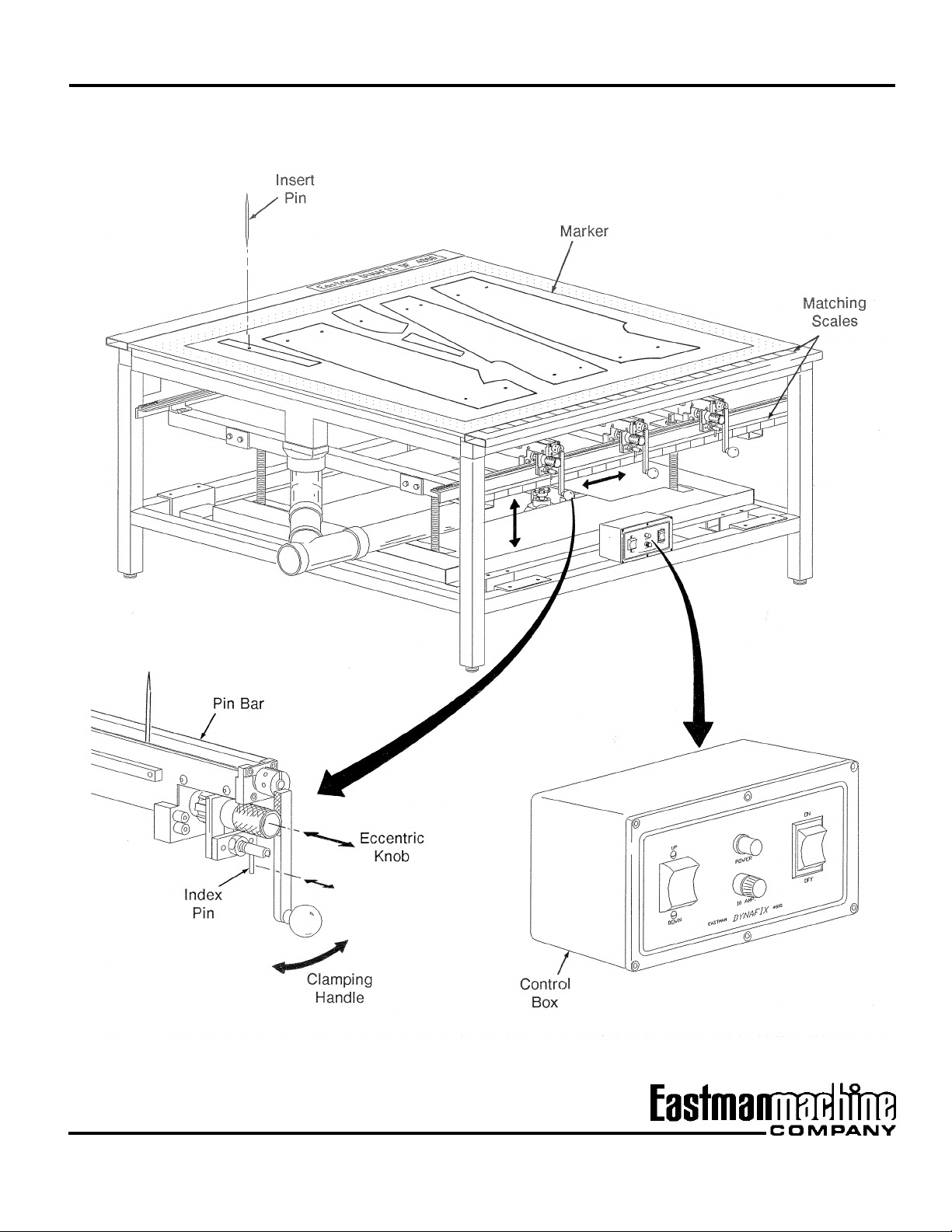
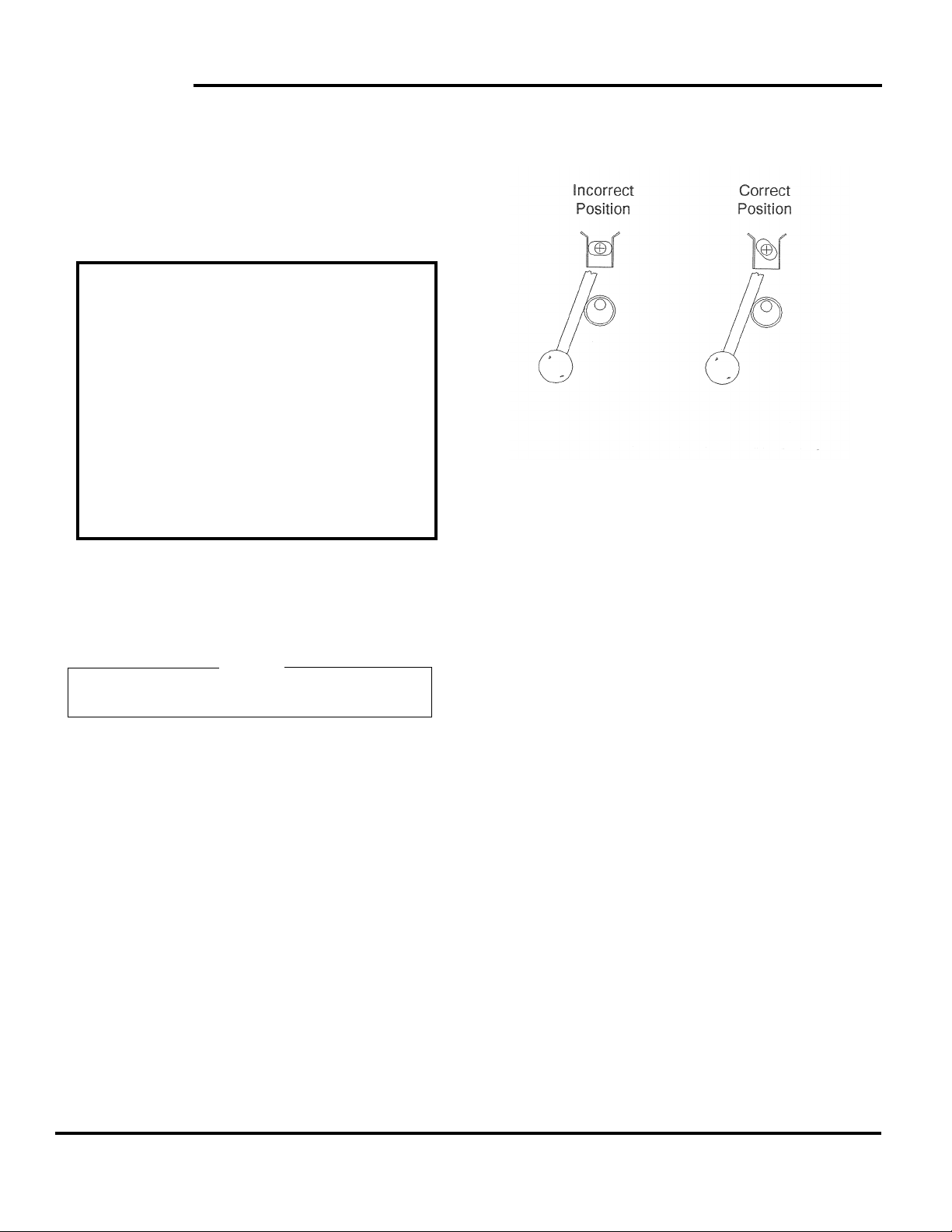
As each pin bar is moved into position the pins can be
inserted through the table top and secured. To secure the
pins, slide the eccentric knob in and swing the clamping
handle into its locking position. Pull the eccentric knob out
to lock the position. After all pins are locked in position the
pins can be lowered to 1/2" to 1" (1 to 2.5 cm.) above the
surface. Remove the marker and spread the material.
NOTE: Proper alignment of stripe, plaid or patterned materi-
als may be critical. The pins should protrude only
enough to secure the layers and care should be
taken when aligning patterns.
Spread & Pin The Fabric
Spread and cut the material to desired length. As each layer
is spread work from one end, align the pattern with the
previous layer and secure its position by pressing the
material over the pins. As the layers are spread the pins must
be raised enough to secure the next few layers. Continue
spreading until the total number of layers have been spread.
For some applications the marker can be placed over the final
layer of material, aligned and pinned in place to allow for
cutting the material from the stack. The optional Servo Cutter
offered by Eastman is equipped with a small base plate to
allow for cutting on the pin table with the pins installed. This
method will eliminate misalignment caused by transfer from
the pin table to a cutting station.
Other applications may require the material to be transported
to another station. For transportation of goods the air flotation
is used. Place down pin units on the material to secure
alignment. The down pin units should be placed away from
the cut lines on the marker and not interfere with the cut.
Lower the pins below the table surface. Press the Down
button on the control box to lower the pins. After the pins are
lowered, press the Start button on the Start/Stop switch to
begin air flotation. The air flotation allows the stack of material
to move with ease off of the table and prevent misalignment
of the material. After the spread is transferred to another
station the next spread can take place.
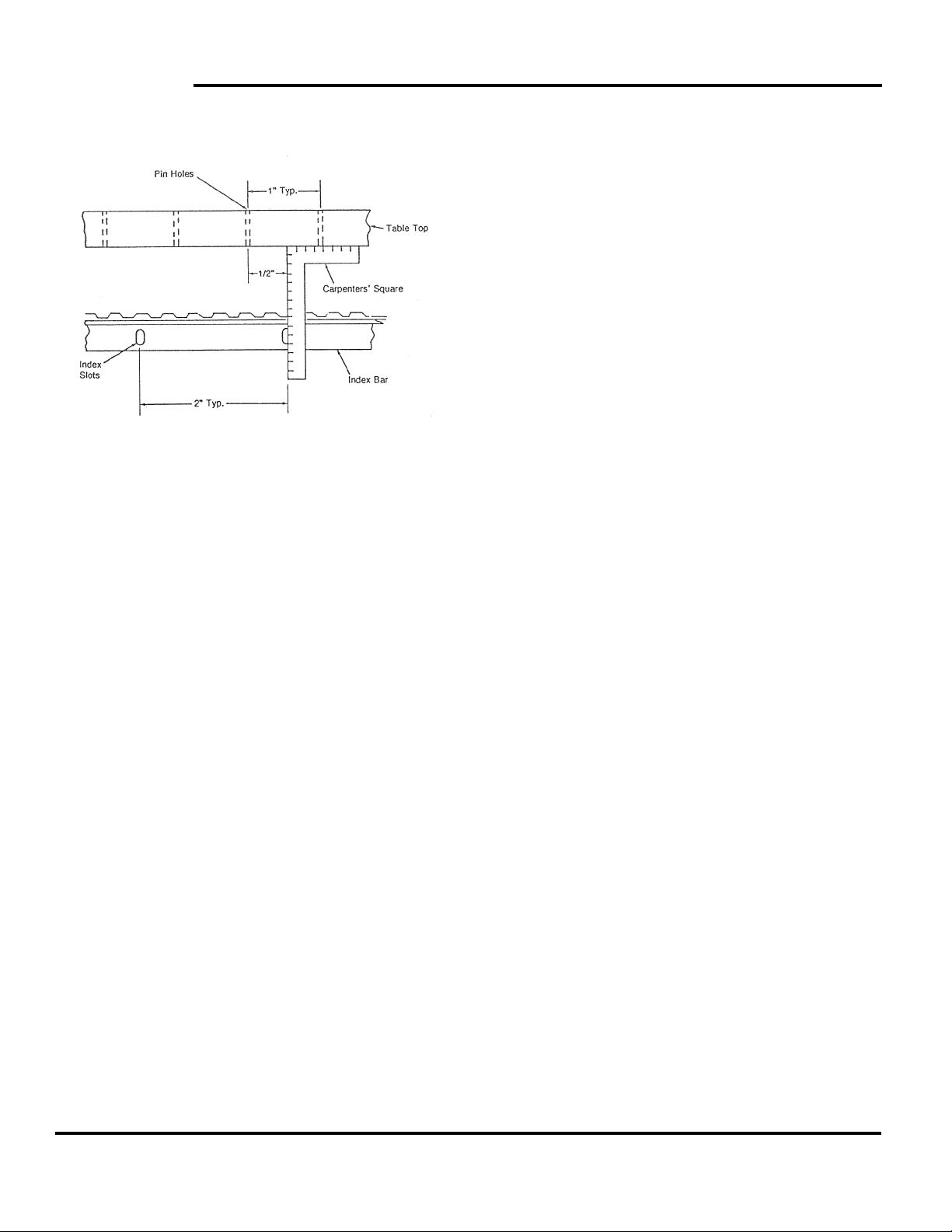
Index Alignment Procedure
When a Pin Table is first installed, the index bar must be
checked for proper alignment with the table top before the pin
bars can be installed.
To check for index bar alignment, hold a carpenters’ square
to the underside of the table top, as shown. The center of the
index slot must be centered between the pin holes (1/2" from
each hole). If the index bar is not centered, loosen the (2) two
screws on the rail bracket (operator’s side) and slide the rail
into position. Secure rail bracket into position.
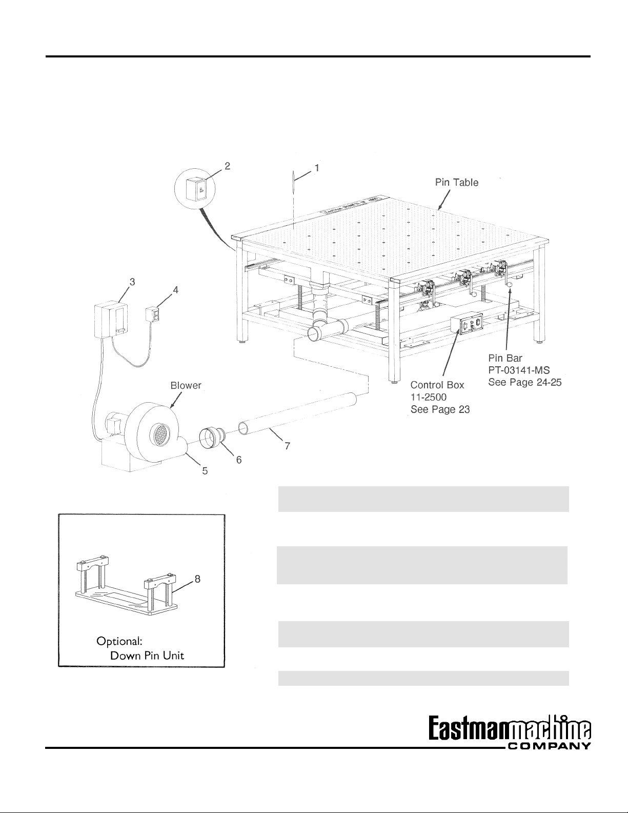
Operation
After the installation procedure has been completed, the
Eastman Dynafix DF 4800 is now ready for operation.
Place the marker on the table surface in the position the
material is to be spread (marker - print paper with a series of
pattern outlines for the purpose of cutting out material). Turn
the main power switch, located on the table frame, to the ON
position. Press the ON/OFF switch on the control box to the
ON position. The power light should light up. Using the UP/
DOWN switch on the control box, raise the pin bars up to the
top position. At this point all pin bars should be located at the
right of each section. Looking at the marker, determine where
the fix points are to be located. Move the pin bars to the
desired location. To move a pin bar pull the index pin, as
shown and move the pin bar. The index pin will lock the pin
bar in position. The matching scales on the table top and the
lift assembly will aid in aligning the pin bars with the pin holes.

5

6
EASTMAN
Before spreading the next stack of material the operator has
the option of removing all the pins or relocate some of the
existing pins. To remove pins, raise the pins up to the top
position. Unlock the pin bars by sliding the eccentric cam in
and swinging the clamp handle to the unlocking position. Pull
the eccentric knob out to secure this position and remove the
pins.
Simplified Operating Instructions
1) Position marker on table surface.
2) Determine fix points.
3) Insert and secure pins in position.
4) Lower pins 1/2" to 1" (1 to 2.5 cm.) above
surface.
5) Remove marker and begin spread.
6) When spreading is complete:
a. place marker in position and begin cut.
b. position down pin units, lower pins and
transport material with air flotaion to next
station.
Maintenance
Use air hose or bellows with proper eye protection and blow
lint or dust from the pin bars and off the table. Clean the table
suface with a mild household cleaner.
Caution
Do not use a strong cleaner on the table top as it may
damage the table top seal.
Fuse Replacement
Replace the fuse located on the control box with a 15 amp.
fuse.
Clamp Bar Adjustment
If pins slip out of the pin bar when the clamp handle is in the
locked postion, the clamp bar assembly may need adjust-
ment. Loosen the socket head screw and the setscrew on
the clamp handle. Position the clamp bar in the position as
shown. Secure the socket head screw and the setscrew in
the clamp handle.
Warning: Improper adjustment of the clamp bar may cause
permanent damage to the pin bar.
Chain Tension
Disconnect the power source. Remove 6 screws from the
motor cover and remove the cover. Loosen the 4 motor/
transformer mount screws. Tighten the chain and secure the
screws. Replace the motor cover.
Lubrication
The gear motor bearings are grease sealed and require no
lubrication.
Chain and Sprocket Shaft
The chain and sprocket shaft can be lubricated without
removing the chain covers. To oil the chain, spray oil on the
chain for 5 seconds while the lift is in motion. The sprocket
shaft can be greased with a general purpose light weight
grease when the lift is in its top position.
Lift Block Bearings
Remove the 2 end chain covers to gain access to the lift
blocks. Each lift block is equipped with one grease fitting.
Grease the bearings with a generous portion of grease.
Replace the covers.

7
Pin Table
Assembly
ITEM PART NO. DESCRIPTION QTY.
1 PT-12220-5-60 Pin, 5/64 x 7 1/2 A/R
PT-12637 Pin, Bulb Type A/R
2 11-4147 Switch, Main ON/OFF 1
11-1342 Thermal Overload Unit
(not shown) 1
3 11-4149 Starter 1
11-1343 Thermal Overload Unit
(not shown) 3
4 11-4148 Blower Switch, START/STOP 1
5 11-6000 Blower, 60HZ. 220v 1
11-6001 Blower, 50HZ. 380v 1
6 PT-12196 Adapter, 6" to 4" 1
7 PT-12225 4" PVC Pipe 1
8 AZ-DP175 Down Pin Assembly, Large 1
AZ-DP175/SM Down Pin Assembly, Small 1
9 AZ-DP175/PIN Replacement Down Pin 1
A/R - As Required

8
EASTMAN
4' End Section
PT-04294-MS
ITEM PART NO. DESCRIPTION QTY.
1 PT-40184-MS Table Top 1
2 9124-053 Decal 1
3 PT-12191 Top Rail 2
4 PT-12192 Upper Side Rail 2
5 PT-21135 Corner Connector, L.H. 1
6 PT-12189-MS Cross Rail 2
7 331-34-10 Screw, Hex Head
1/4-20 x 5/8 6
8 PT-12179 Table Top Support 2
9 331-38-40 Screw, Hex Head
3/8-16 x 2 1/2 28
10 402-38 Washer, Lock 3/8 28
11 205-38 Nut, Hex 3/8-16 28
12 PT-21134 Corner Connector, R.H. 1
13 335-36-12 Screw, Socket Head
5/16-18 x 3/4 14
14 331-38-48 Screw, Hex Head
3/8-16 x 3 8
15 402-38 Washer, Lock 3/8 8
16 205-38 Nut, Hex 3/8-16 8
17 PT-12182 Lower Side Rail 2
18 PT-12186 Corner Leg 2
19 PT-12184 LegLeveler 2
R.H.-Right Hand
L.H.-Left Hand
MS-Machine Size

9

10
EASTMAN
8' End Section
PT-04277-MS (Left) shown
PT-04290-MS (Right)
ITEM PART NO. DESCRIPTION QTY. ITEM PART NO. DESCRIPTION QTY.
20 PT-12194 90oElbow 1
21 PT-12203 4" PVC, 6" Long
(Left End only) 1
PT-12204 4" PVC, 5" Long
(Right End only) 1
22 PT-12197 “Y” Coupling, 4” PVC
(Left End only) 1
PT-12198 45oElbow, 4" PVC
(Right End only) 1
23 PT-12193 4" PVC (Left End only) 1
PT-12202 4" PVC (Right End only) 1
24 PT-12181 Lower Side Rail 2
25 PT-12186 Corner Leg 2
26 PT-12184 Leg Leveler 2
27 PT-12189-MS Lower Cross Rail 1
28 331-38-48 Screw, Hex Head
3/8-16 x 3 8
29 402-38 Washer, Lock 3/8 8
30 205-38 Nut, Hex 3/8-16 1
R.H.-Right Hand
L.H.-Left Hand
MS-Machine Size
1 PT-04182-MS Table Top 1
2 9124-053 Decal 1
3 PT-12188 Top Rail 2
4 PT-12187 Upper Side Rail 2
5 PT-21135 Corner Connector, L.H. 1
6 PT-30350-MS Manifold Bar, 1 Sided 1
7 335-36-12 Screw, Socket Head
5/16-18 x 3/4 28
8 363-12-12 Screw, Self Tap #12 x 3/4 12
9 PT-12179 Table Top Support 4
10 331-34-10 Screw, Hex Head
1/4-20 x 5/8 16
11 402-34 Washer, Lock 1/4 4
12 410-34 Washer, Flat 1/4 4
13 PT-21136-MS Upper Support 1
14 PT-12172 Scale, Left to Right 1
PT-12173 Scale, Right to Left 1
15 331-38-40 Screw, Hex Head
3/8-16 x 2 1/2 28
16 402-38 Washer, Lock 3/8 28
17 205-38 Nut, Hex 3/8-16 28
18 PT-21134 Corner Connector, R.H. 1
19 PT-12195 Adapter 4" to 3" 1

11

12
EASTMAN
8' Middle Section
PT-04292-MS
ITEM PART NO. DESCRIPTION QTY.
1 PT-40183-MS Table Top 1
2 9124-053 Decal 1
3 PT-12188 Top Rail 2
4 PT-12190 Upper Side Rail 2
5 335-36-12 Screw, Socket Head
5/16-18 x 3/4 28
6 PT-30351-MS Manifold Bar 2
7 363-12-12 Screw, Self Tap #12 x 3/4 12
8 PT-12179 Table Top Support 4
9 331-34-10 Screw, Hex Head
1/4-20 x 5/8 16
10 402-34 Washer, Lock 1/4 4
11 410-34 Washer, Flat 1/4 4
12 PT-21136-MS Upper Support 1
13 PT-12172 Scale, Left to Right 1
PT-12173 Scale, Right to Left 1
14 PT-12195 Adapter 2
15 PT-12194 90oElbow, 4" PVC 2
16 PT-12203 6" PVC, Short 2
17 PT-12197 “Y” Coupling, 4” PVC 2
18 331-38-40 Screw, Hex Head
3/8-16 x 2 1/2 40
19 402-38 Washer, Lock 3/8 40
20 205-38 Nut, Hex 3/8-16 40
21 PT-12201 Sleeve 4
22 PT-21133 Center Connector 4
23 PT-12202 4" PVC, Long 1
24 PT-12185 Center Leg 4
25 PT-12184 Leg Leveler 4
26 PT-12180 Lower Side Rail 2
27 PT-12189 Lower Cross Rail 2
28 331-38-48 Screw, Hex Head
3/8-16 x 3 8
29 402-38 Washer, Lock 3/8 8
30 205-38 Nut, Hex 3/8-16 8
MS-Machine Size

13

14
EASTMAN
8' Additional Section
PT-04293-MS
ITEM PART NO. DESCRIPTION QTY.
1 PT-04183-MS Table Top 1
2 PT-12188 Top Rail 2
3 PT-12190 Upper Side Rail 2
4 335-36-12 Screw, Socket Head
5/16-18 x 3/4 28
5 363-12-12 Screw, Self Tap #12 x 3/4 12
6 PT-12179 Table Top Support 4
7 331-34-10 Screw, Hex Head
1/4-20 x 5/8 12
8 402-34 Washer, Lock 1/4 4
9 410-34 Washer, Flat 1/4 4
10 331-34-10 Screw, Hex Head
1/4-20 x 5/8 4
11 PT-21136-MS Upper Support 1
12 9124-053 Decal 1
13 PT-12201 Sleeve 2
14 PT-21133 Center Connector 2
15 PT-30351-MS Manifold Bar, 2 Sided 1
16 331-38-40 Screw, Hex Head
3/8-16 x 2 1/2 28
17 402-38 Washer, Lock 3/8 28
18 205-38 Nut, Hex 3/8-16 28
19 PT-12172 Scale, Left to Right 1
PT-12173 Scale, Right to Left 1
20 PT-12195 Adapter 4" to 3" 1
21 PT-12194 90oElbow, PVC 1
22 PT-12203 4' PVC, Short 1
23 PY-12197 4" PVC, “Y” Coupling
24 PT-12202 4" PVC, Long 1
25 PT-12185 Center Leg 2
26 PT-12189-MS Lower Cross Rail 1
27 PT-12184 Leg-Leveler 2
28 205-38 Nut, Hex 3/8-16 8
29 402-38 Washer, Lock 3/8 8
30 331-38-48 Screw, Hex Head
3/8-16 x 3 8
31 PT-12180 Lower Side Rail 2
MS-Machine Size

15

16
EASTMAN
Middle Section Kit
PT-04291-MS
ITEM PART NO. DESCRIPTION QTY.
1 PT-21133 Center Connector 2
2 PT-12201 SleeveTube 2
3 PT-30351-MS Manifold, 2 Sided 1
4 205-38 Nut, Hex 3/8-16 28
5 402-38 Washer, Lock 3/8 28
6 331-38-40 Screw, Hex Head
3/8-16 x 2 1/2 28
7 PT-12195 4" Adapter 1
8 PT-12194 90oElbow 1
9 PT-12203 4" PVC Pipe 1
10 PT-12197 “Y” Coupling 1
11 PT-12185 Center Leg 2
12 PT-12189 Lower Cross Rail 1
13 PT-12184 Leg Leveler 2
MS-Machine Size

17

18
EASTMAN
Lift Assembly
PT-04284-MS (4' Lift)
PT-04283-MS (8' Lift)
ITEM PART NO. DESCRIPTION QTY.
1 332-93-6 Screw, Flat Head 8-32 x 3/8 A/R
2 9013-006 Track 16 ft.
3 PT-12176 Track Spacer (4' only) 2
PT-12175 Track Spacer (8' only) 2
4 PT-02391 Rail Bracket, non-opp.
(4' only) 1
PT-02389 Rail Bracket, non-opp.
(8' only) 1
5 335-34-8 Screw, Socket Head
1/4-20 x 1/2 4
6 PT-12208 Rail Insert 2
7 335-102-6 Screw, Socket Head
10-32 x 3/8 4
8 203-38 Nut, Hex 3/8-16 8
9 402-38 Washer, Lock 3/8 8
10 PT-21132-MS Lift Tube 2
11 PT-02390 Rail Bracket, opp. (4' only) 1
PT-02388 Rail Bracket, opp. (8' only) 1
12 PT-21104 Index Bar 4' (4' only) 1
PT-21105 Index Bar 8' (8' only) 1
13 332-102-6 Screw, Flat Head
10-32 x 3/8 3
14 332-102-8 Screw, Flat Head
10-32 x 1/2 2
15 PT-21126 Scale Angle 4' (4' only) 1
PT-21127 Scale Angle 8' (8' only) 1
16 PT-21128-MS Cover, Motor Side 1
17 361-8-6 Screw, Round Head 8-3/8 8
18 PT-21130-MS Cover, Non-Motor Side 1
19 PT-30352 Cover, Chain (4' only) 2
PT-30348 Cover, Chain (8' only) 2
20 335-34-72 Screw, Socket Head
1/4-20 x 4 1/2 8
21 PT-12219 Cover Spacer 4
22 PT-03150 Sprocket Assembly 4
23 203-43 Nut, Hex 1/2-13 8
ITEM PART NO. DESCRIPTION QTY.
24 402-44 Washer, Lock 1/2 8
25 331-38-48 Screw, Hex Head
3/8-16 x 3 4
26 410-38 Washer, Flat 3/8 4
27 PT-03153-MS Cross Member, Lift Support 2
28 335-43-20 Screw, Socket Head
1/2-13 x 1 1/4 8
29 11-1610-1 Transformer (220v option) 1
30 331-34-16 Screw, Hex Head 1/4-20 x 1 4
31 410-34 Washer, Flat 1/4 8
32 402-34 Washer, Lock 1/4 4
33 203-34 Nut, Hex 1/4-20 4
34 205-36 Nut, Hex 5/16-18 4
35 402-36 Washer, Lock 5/16 4
36 410-36 Washer, Flat 5/16 4
37 PT-30349 Motor/Transformer Mount 1
38 410-38 Washer, Flat 3/8 4
39 402-38 Washer, Lock 3/8 4
40 205-38 Nut, Hex 3/8-16 4
41 11-1235 Motor, 1/2 hp 1
42 331-36-20 Screw, Hex Head
5/16-18 x 1 1/4 4
43 603-6-6-14 Square Key 1
44 342-34-8 Setscrew, 1/4-20 x 1/2 2
45 9009-0208 Sprocket 1
46 203-34 Nut, Hex 1/4-20 8
47 402-34 Washer, Lock 1/4 8
48 9142-204-001 Chain Assembly (4' only) 1
9142-231-001 Chain Assembly (8' only) 1
49 331-38-48 Screw, Hex Head
3/8-16 x 3 8
50 PT-12172 Scale, Left to Right 1
PT-12173 Scale, Right to Left 1
51 9093-002 Trim Adhesive (not shown) 1
MS-Machine Size

19

20
EASTMAN
Sprocket Assembly
PT-03150
ITEM PART NO. DESCRIPTION QTY.
1 217-52 Nut, Elastic Hex 3/4-16 1
2 410-51 Washer, Flat 3/4 1
3 PT-21124 Screw Bracket 1
4 331-38-48 Screw, Hex Head
3/8-16 x 3 2
5 402-38 Washer, Lock 3/8 2
6 203-38 Nut, Hex 3/8-16 2
7 PT-21125 Screw Shaft 1
8 PT-12218 Sprocket, Large 1
9 342-34-8 Setscrew, 1/4-20 x 1/2 1
10 PT-12170 Bronze Nut 1
11 342-34-8 Setscrew, 1/4-20 x 1/2 2
12 9031-006 Flange Block 1
13 335-43-20 Screw, Socket Head
1/2-13 x 1 1/4 2
14 402-44 Washer, Lock 1/2 2
15 203-43 Nut, Hex 1/2-13 2
Table of contents
Other EASTMAN Industrial Equipment manuals

EASTMAN
EASTMAN TRIGGER PLUS Knifebox User manual

EASTMAN
EASTMAN HVN User manual

EASTMAN
EASTMAN E Series User manual

EASTMAN
EASTMAN RS2 User manual

EASTMAN
EASTMAN Kodak X-Omatic 4 User manual

EASTMAN
EASTMAN 534 Setup guide

EASTMAN
EASTMAN 1050VB User manual

EASTMAN
EASTMAN Kodak X-Omat 180 LP User manual

EASTMAN
EASTMAN C Series Setup guide

EASTMAN
EASTMAN Blue streak II 629X User manual